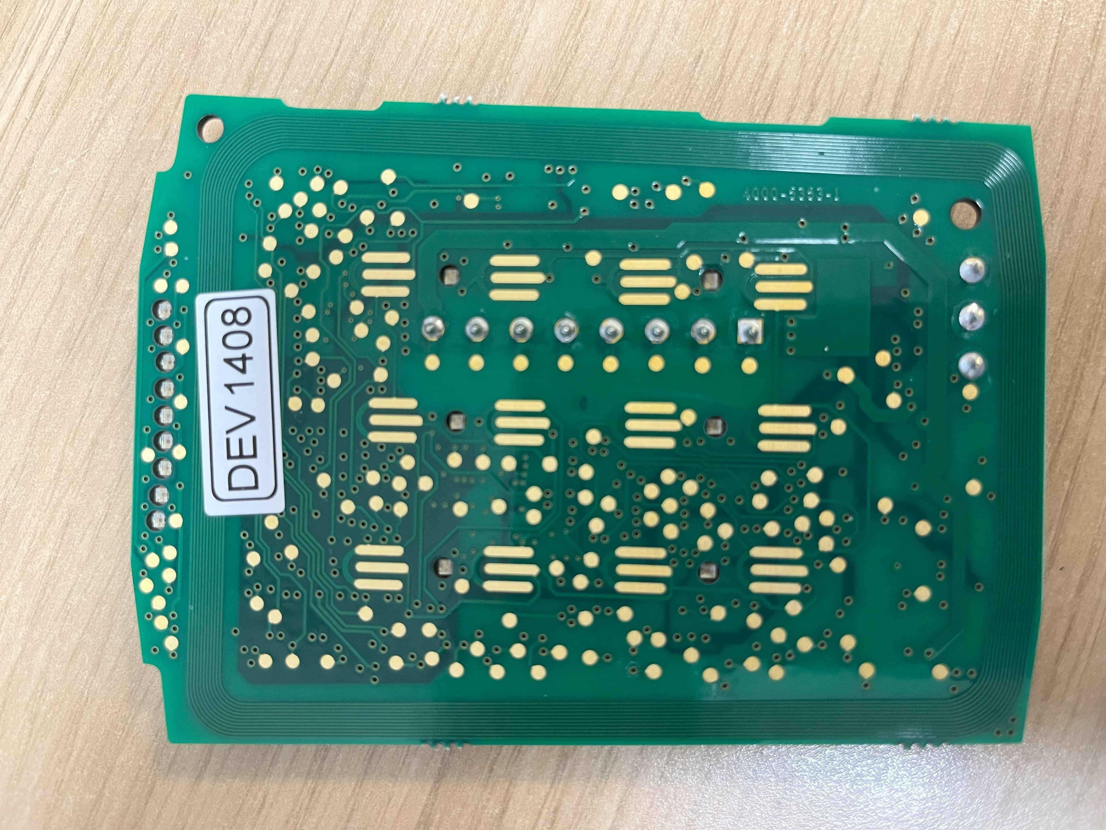
OE5S884CAccess Control Keypad Reader 884 MKII
G4S Technology Limited
Click to zoom
Application Details
- Equipment Class
- DXX - Part 15 Low Power Communication Device Transmitter
- Date of Grant
- Dec 22, 2025
- Application Purpose
- Original Equipment
- Equipment Note
- Access Control Keypad Reader 884 MKII
- Frequency Range
- 13.56000000 - 13.56000000
- Company
- G4S Technology Limited
- Country
- United Kingdom
Documents & Files
Document Text
Text extracted from the exhibit documents filed with the FCC. Open a document above to read the original.
Users Manual
Mount the backplate using countersunk headed screws adjacent to the opening edge of door. For UL1076 installations UL listed Electrical Back Boxes are required. If fixing hole ’A’ is used then the breakout must be removed and the screw must not protrude. Feed the required cables through the backplate: ∑The cable from the controller. 2 1 Mount the Backplate Reader Connections The S884 V4 is a The reader can be set to use Wiegand or 20mA current loop communications for Indoor Use Only. The S884 V4 reader will read smartMAX encoded MIFARE cards and card serial numbers from most ISO 14443A smart cards which have a 4-byte UID (User Identification). The reader may be configured to read other card types by presenting a programming card to the reader during start up. Only DES-CARD and DES-CARD-W/MAG DESfire 32K bit smart cards have been evaluated for UL294 and UL1076. For additional information regarding the installation, configuration and proper use of this product: SMS User Guide, P/N 9600-0429, M2150 Access Control Design Guide, P/N 9600-0420, M2150 Intrusion Guide, P/N 9600-0540 and M2150 UL1076 Compliance Manual, P/N 9600-0449. contactless smart-card reader, with Graphic LCD and keypad. You should find that the backplate has holes for connection to most standard electrical backboxes. C A B Installation and User Instructions for S884 V4 Readers 0V RX+ RX- TX+ TX- 12V Controller 0V TX+ TX- RX+ RX- +V Reader TB1 20mA current loop 0V Green Data 0 Red Data 1 12V Controller 0V GRN 0 +V Wiegand (Not evaluated by UL) RED 1 Reader TB1 Connect shield at controller end only. Connect shield at controller end only. Note: Use LK2 to select the communications mode (See Step 3). Slide the ferrite sleeve onto cable before wiring terminal block. Ferrite to be placed 50mm (2") up cable and held in place with cable ties. Note: The FERRITE must be fitted! Note: 1). Consult local AHJ (Authority Having Jurisdiction) when installing access control readers and locking mechanisms to any portal in an egress path. 2). The use of Fail Closed / secure configuration shall be determined by local building codes and the local AHJ. 3). Wiring methods shall be in accordance with NEC (National Electrical Code) ANSI/NFPA 70. 4). For UL1076 Host Communications the following controllers are evaluated M2150-2DBC, -2DC, -4DBC, -4DC, -8DBC, -8DC. 5). All Interconnected devices must be UL listed. 6). The internal tamper switch must be configured at the controller for UL1076 compliance. Twisted pairs (Use Belden 9503) or other UL Listed style 2464 (DUZX) cable. Multi-conductor (Use Belden 9537) or other UL Listed style 2464 (DUZX) cable. Maximum distance 100m Maximum distance 75m Terminal TB1 is rated class 2 The securing screws ‘C’ are integral to the backplate and accessed via the two small holes at the bottom of the front enclosure. IMPORTANT: Ensure not to over tighten screws as it may damage the housing. To secure the front housing to the backplate the screws will need to be turned counter-clockwise until the screw head makes contact with the inside face of the front housing. A maximum of one additional half turn is permitted if required. If wall tamper function is to be used then breakout ‘B’ must be removed and an appropriate wall screw fitted through the hole to actuate the tamper lever. 4 External Reader Connections (Optional) 0V 0/CK 1/D +V Reader TB1 Magstripe 0V 0/C 1/D +V Reader TB1 Wiegand (Not evaluated by UL) Wiegand Reader Magstripe Reader Presentthe cardface-ontothereaderuntilyouhear a"bleep". The reader is now working properly. Cardscanbe presented in rapid succession; there is no need, for example, to wait for "UNLOCKED" to disappear before presenting another. If the reader has been enabled for user-code mode at the controller, you can gain access by pressing the O key, entering your card number, then pressing the P key. When faulted, the reader cannot accept a card read. Check wiring for faults or replace reader. The reader, by default, retain the formats from the first two cards used. In addition to the card format retention, the readers allow the first two card formats learnt by the reader to be locked. Instructions to 'Lock' the formats: ∑Ensure that the reader has learnt the two required formats. ∑Navigate through the setup menu to 'Card Learning'. ∑Set the 'Card Types Locked' to yes 'Y' and Exit. A Setup menu can be displayed by pressing the O and P keys simultaneously while power is applied. You can use the menu to change the contrast and language used for the LCD (default English). Use the four function keys to navigate around the menu. Please refer to M2150 Intrusion Guide, 9600-0540 for IDS Arm / Disarm procedure. 9600-0777. Installation and User Instructions for S884 V4 Readers, Issue 1.2. © AMAG Technology, 2024. FCC Notice: This device complies with Part 15 of the FCC Rules. Operation is subject to the following two conditions: (1) This device may not cause harmful interference, and (2) this device must accept any interference received, including interference that may cause undesired operation. Any unauthorized modification to this device may void the authority of the user to operate it. All trademarks acknowledged. LED Status Indicator GREEN – The lock is released and you may open the door. RED – No access rights to gain entry, or the reader did not read your card properly. Present a card again. YELLOW – Enter your PIN. If you make a mistake, the message INVALID PIN is momentarily displayed, followed by ENTER PIN, to prompt you to try again. Specifications: Input voltage: 13Vdc (Nominal) (Voltage Source is Class 2 Power Limited) Input current: 320mA max Operating temperature: 32 to 120°F (0 to 49°C) Operating humidity: 15 to 90%, non-condensing Maximum read range: 4" (100mm) Approvals: EN300330, EN301489, UL294 (8th Edition) Performance Levels: Destructive Attack - Level 1Line Security - Level 1 Endurance - Level IVStandby Power - Level 1 Firmware Version: 1.XX 5 Using / Testing the Reader Note: Use L…
Text truncated - open the document above for the full version.
Attestation Statements
Date: October 14, 2024 Certification Attestation Statements for FCC ID OE5S884C Attn: Federal Communications Commission Authorization and Evaluation Division 7435 Oakland Mills Road Columbia, MD 21046 USA To Whom It May Concern: 47 CFR section 2.911(d)(5)(i) Attestation Statement G4S Technology Limited certifies that as of the date of the application the equipment for which authorization is sought is not “covered” equipment 1 prohibited from receiving an equipment authorization pursuant to section 2.903 of the FCC rules. As per KDB 986446 D01 Covered Equipment Guidance v03 section B paragraph 2a, G4S Technology Limited certifies that the equipment for this application does not contain Kaspersky Lab, Inc. (or any of its successors and assignees) cybersecurity or anti-virus software. If the equipment for which the applicant seeks authorization is produced by any of the entities identified on the current Covered List, including affiliates or subsidiaries of the named companies, the applicant must include an explanation on why the equipment is not “covered” equipment. Additional Explanation: not required 47 CFR section 2.911(d)(5)(ii) Attestation Statement G4S Technology Limited (“the applicant”) certifies that, as of the date of the filing of this application, the applicant is not identified on the Covered List (as a specifically named entity or any of its subsidiaries or affiliates) as an entity producing “covered” equipment. Thank you, Signature: Name: Mr Ian Williams Title: Hardware Team Lead Company: G4S Technology Limited (trading as AMAG Technology) Tel #: +44 7734362323 1 - The Commission’s Covered List is published by the Public Safety and Homeland Security Bureau and posted on the Commission’s website. This Covered List, which is periodically updated, identifies particular equipment, produced by particular entities, that constitutes “covered” equipment. https://www.fcc.gov/supplychain/coveredlist .
Cover Letter(s)
AMAG Technology Challenge House International Drive Tewkesbury Gloucestershire GL20 8UQ UK Telephone: +44 (0) 1684 850977 www.amag.com Registered Office: AMAG Technology is a trade name of G4S Technology Ltd Challenge House, International Drive Tewkesbury, Glos, GL20 SUQ Registered Number: 02382338 England. A member of the British Security Industry Association 1151/7.17 For the attention of: Federal Communications Commission Authorization and Evaluation Division 7435 Oakland Mills Road Columbia, MD 21046 USA 29 th October 2024 Submission of FCC ID OE5S884C for Equipment Authorisation G4S Technology Limited (trading as AMAG Technology) submits the following equipment for equipment authorisation: FCC ID OE5S884C Product Numbers 884-KP-V4, 884-KP-V4-S, 884-KP-V4-DPD, 884-KP-V4-OSDP Description Smartcard reader with keypad and LCD display for access control systems Radio type Inductive loop (near field magnetic field) short range device (SRD) for radio frequency identification (RFID). Frequency 13.56 MHz Nominal field strength 6.66 dBμA/m at 10m (120μV/m at 30m) Band 13.110 to 14.010 MHz Channel spacing Not channelised Wide/narrow band Wideband Modulation Amplitude Shift Keying Antenna Integrated loop antenna Applicant G4S Technology Limited Applicant type Manufacturer Authorisation sort Original certification Applicable rule parts CFR Title 47, Chapter I, Subchapter A, Part 15, Subpart C, § 15.225 Operation within the band 13.110-14.010 MHz (47 CFR 15.225) G4S Technology Limited certifies that all statements it makes in this request for equipment authorisation are true and correct to the best of its knowledge. G4S Technology Limited certifies that neither it nor any party to the application is subject to a denial of Federal benefits pursuant to section 5301 of the Anti-Drug Abuse Act of 1988. Signed on behalf of G4S Technology Limited, Mr Ian Williams Hardware Team Lead Tel: +44 7734362323 Email: [email protected]
Cover Letter(s)
AMAG Technology Challenge House International Drive Tewkesbury Gloucestershire GL20 8UQ UK Telephone: +44 (0) 1684 850977 www.amag.com AMAG Technology is a trade name of G4S Technology Ltd Registered Office: Challenge House, International Drive, Tewkesbury, Glos, GL20 8UQ Registered Number: 02382338 England. A member of the British Security Industry Association 1151/7.17 For the attention of: Federal Communications Commission Authorization and Evaluation Division 7435 Oakland Mills Road Columbia, MD 21046 USA 16 th October 2025 DECLARATION OF SIMILARITY G4S Technology Limited, trading as AMAG Technology, declares that the following products: 884-KP-V4-S 884-KP-V4-DPD 884-KP-V4-OSDP are identical with regards to radio performance and electromagnetic compatibility performance as product number: 884-KP-V4 that was tested and assessed by Element Material Technology Warwick Limited. All of the above products will be identified by the FCC ID: OE5S884C. All of the above products share the same circuit board and firmware. The differences are as follows: Product Difference Ending ...-S,-DPD These denote cosmetic differences for some customers, or regional markets where the label is different for regulatory purposes. Ending ...-OSDP These readers can also communicate with the control panel using the Open Supervised Device Protocol over RS-485. Signed on behalf of G4S Technology Limited, Mr Ian Williams Hardware Team Lead Tel: +44 7734362323 Email: [email protected]
Cover Letter(s)
Date: October 14, 2024 Certification Attestation Statements for FCC ID OE5S884C Attn: Federal Communications Commission Authorization and Evaluation Division 7435 Oakland Mills Road Columbia, MD 21046 USA To Whom It May Concern: 47 CFR section 2.911(d)(5)(i) Attestation Statement G4S Technology Limited certifies that as of the date of the application the equipment for which authorization is sought is not “covered” equipment 1 prohibited from receiving an equipment authorization pursuant to section 2.903 of the FCC rules. As per KDB 986446 D01 Covered Equipment Guidance v03 section B paragraph 2a, G4S Technology Limited certifies that the equipment for this application does not contain Kaspersky Lab, Inc. (or any of its successors and assignees) cybersecurity or anti-virus software. If the equipment for which the applicant seeks authorization is produced by any of the entities identified on the current Covered List, including affiliates or subsidiaries of the named companies, the applicant must include an explanation on why the equipment is not “covered” equipment. Additional Explanation: not required 47 CFR section 2.911(d)(5)(ii) Attestation Statement G4S Technology Limited (“the applicant”) certifies that, as of the date of the filing of this application, the applicant is not identified on the Covered List (as a specifically named entity or any of its subsidiaries or affiliates) as an entity producing “covered” equipment. Thank you, Signature: Name: Mr Ian Williams Title: Hardware Team Lead Company: G4S Technology Limited (trading as AMAG Technology) Tel #: +44 7734362323 1 - The Commission’s Covered List is published by the Public Safety and Homeland Security Bureau and posted on the Commission’s website. This Covered List, which is periodically updated, identifies particular equipment, produced by particular entities, that constitutes “covered” equipment. https://www.fcc.gov/supplychain/coveredlist .
Cover Letter(s)
AMAG Technology Challenge House International Drive Tewkesbury Gloucestershire GL20 8UQ Telephone: 01684-850977 www.Amag.com REQUEST FOR CONFIDENTIALITY IN ACCORDANCE WITH FCC RULE 0.459 12 th June 2024 Element Materials Technology Warwick Ltd 100 Frobisher Business Park Leigh Sinton Road Malvern Worcestershire WR14 1BX UK RE: Certification Application FCC ID: OE5S884C To Whom It May Concern: Please be advised that the following information is to be held confidential on behalf of AMAG Technology Limited. Schematics Parts Lists Block Diagram Operational Description The application contains technical information, which AMAG Technology Limited deems to be trade secrets and propriety. If made public, the information might be used to the disadvantage of the applicant in the market place. Thank you for your attention to this matter. Yours faithfully AMAG Technology Limited Challenge House International Drive Tewkesbury Gloucestershire GL20 8UQ Issued by:- Date:- 12/06/2024 Ian Williams (Hardware Team Lead)
Cover Letter(s)
AMAG Technology Challenge House International Drive Tewkesbury Gloucestershire GL20 8UQ Telephone: 01684-850977 www.Amag.com Letter of Authorization Date: 20th June 2024 FCC ID: 0E5S884C Re: Letter of Authorization TO WHOM IT MAY CONCERN We, G4S Technology ltd. hereby declare that company: Name: AMAG Technology ltd. Address: Challenge House International Drive Tewkesbury Gloucestershire GL20 8UQ and their associates have been authorized to act on our behalf for all acts relating to the global approval/declaration certification of the following product(s) in the United States: FCC ID: 0E5S884C Product Name: S884 MKII Javelin Reader Sincerely, Printed name: Ian Williams Signature Job Title: Hardware Team Lead Company Name: G4S Technology ltd.
ID Label/Location Info
884-KP-V4-DPD 884-KP-V4-OSDP
RF Exposure Info
RF EXPOSURE REPORT INFORMATION 2025-02-04 Element Job Number: Ple ase provide the requested support information by filling in the blanks. If an item does not apply, please fill in the section with ‘NA’. The following information is for Model (or System): The dimensions (XYZ) of the system: RF Exposure conditions: Minimum distance from user during intended product use mm cm What prevents a user from being closer than this? ex: distance from edge of enclosure, mounted to a wall, etc Location on/near body during use Head/Torso Limbs/Extremities Not Applicable Body-worn accessories None Rat ed Power: The rated power is the maximum RF output power your radio equipment is designed to transmit. List the rated power below along with units. If the value is radiated, please list EIRP or ERP as relevant. For the EU, the rated transmit power is listed in the user manual. Tune-up Tolerance: The tune-up tolerance is the variability in the RF output power than can be expected due to manufacturing variation, in (dB). The maximum permitted tolerance is 2 dB. An tenna Gain: If the antenna gain is specific to a frequency range or band, please list the information on a separate line. For loop antennas, no gain is required. List 'loop'. Min imum Distance: If the minimum distance from the antenna to the enclosure exceeds 5 mm (for portable use), please submit a photo with a ruler showing this measurement, or a CAD drawing with a dimension as a separate document. Radio Type Rated Power Tune-up Tolerance (dB) Antenna Gain (dBi) Minimum Distance from Antenna to Enclosure (mm) RF EXPOSURE REPORT INFORMATION 2022-04-01 Simultaneous Transmission: If the radio is capable of simultaneous transmission (when two different radios transmit at the same time) with another radio in the product or system, please include the details below. Otherwise, select ‘NA’. Case List of radios that can simultaneously transmit. 1 NA 2 NA 3 NA 4 NA O perational Duty Cycle: If the transmitters are designed to operate at a reduced duty cycle, please provide a separate document showing a derivation of the operational duty cycle. If the operational duty cycle is not inherent in the channel access mechanism, such as TDMA, this information will need to be documented in the report. See 2.4 GHz sample below which considers all modes when determining worst case duty cycle: Description Payload (bytes) Rate (bytes/sec) Duration (sec) Time between payloads (sec) Period Allowed (sec) Duty cycle (%) Status data 100 500 0.2 30 100 0.7% Streaming 175 500 0.35 0.01 100 97.2% Firmware (one time) 40000 500 80 N/A 100 80.0% So urce-Based Time Averaging (FCC KDB 447498) – A time average of instantaneous exposure over a period that is based on an inherent property or duty-cycle of a device to ensure compliance with the continuous exposure limits. The maximum observation period that can used for the duty cycle calculation is: <3 GHz: 100 seconds, 3-6 GHz: 60 seconds, 6-10 GHz: 30 seconds, 10-16 GHz: 14 seconds, 16-24 GHz: 8 seconds, 24-42 GHz: 4 seconds, 42 - 95 GHz: 2 seconds. (or 6 minutes for ISED). Select which applies: Assessment to be completed assuming 100% duty cycle All Radios Only the following radios: Duty cycle analysis will be provided as a separate document for each of the following radios: Reduced duty cycle radios: C ompleted by (name): Title: Company: Date: Email: S ubmit completed form to [email protected].
RF Exposure Info
RF914 9.0 Page 1 of 1 1 RF Exposure General SAR test reduction & exclusion guidance KDB 447498 Section 4.3 General SAR test reduction and exclusion guidance For Standalone SAR exclusion consideration, when SAR Exclusion Threshold requirement in KDB 447498 is satisfied, standalone SAR evaluation for general population exposure conditions by measurement or numerical simulation is not required. The SAR Test Exclusion Threshold for frequencies below 100 MHz, and for test separation distance of ≤ 50 mm, is determined as follows. SAR Exclusion Threshold (SARET) = [(NT x TSDA) / √ 0.1] x [1 + Log (100 / F MHz )] x 1/2 Where, NT = Numeric Threshold (3.0 for 1-g SAR and 7.5 for 10-g SAR) TSDA = 50 mm fMHz = Transmit frequency in MHz Channel Frequency (MHz) EIRP (mW) SAR Exclusion Threshold at 5 mm (mW) SAR Evaluation 13.56 0.0023 443 Excluded Therefore standalone SAR evaluation for general population exposure conditions by measurement or numerical simulation is not required.
Test Report
RF914 9.0 Report on the Radio Testing For G4S Technology Ltd T/AS AMAG Technology on S884 MK2 Report no. TRA-061464-47-00B 12th December 2025 RF914 9.0 REPORT ON THE RADIO TESTING OF A G4S Technology Ltd T/AS AMAG Technology S884 MK2 WITH RESPECT TO SPECIFICATION FCC 47CFR 15.225 TEST DATE: 21st - 29th August 2023 Tested by: D Winstanley Radio Senior Test Engineer Approved by: J Charters Lab Manager Date: 12th December 2025 Disclaimers: [1] THIS DOCUMENT MAY BE REPRODUCED ONLY IN ITS ENTIRETY AND WITHOUT CHANGE [2] THE RESULTS CONTAINED IN THIS DOCUMENT RELATE ONLY TO THE ITEM(S) TESTED Report Number: TRA-061464-47-00B Issue: B Report Number: TRA-061464-47-00B RF914 9.0 Page 3 of 37 1 Revision Record Issue Issue Date Revision History A 2nd August 2024 Original B 12th December 2025 Update of ANSI C63.10 to 2020 version Report Number: TRA-061464-47-00B RF914 9.0 Page 4 of 37 2 Summary TEST REPORT NUMBER: TRA-061464-47-00B WORKS ORDER NUMBER: TRA-061464-01 PURPOSE OF TEST: USA: Testing of radio frequency equipment per the relevant authorization procedure of chapter 47 of CFR (code of federal regulations) Part 2, subpart J.. TEST SPECIFICATION: 47CFR15.225 EQUIPMENT UNDER TEST (EUT): S884 MK2 FCC IDENTIFIER: OE5S884C EUT SERIAL NUMBER: Not Stated MANUFACTURER/AGENT: G4S Technology Ltd T/AS AMAG Technology ADDRESS: Challenge House International Drive Tewkesbury Gloucestershire GL20 8UQ United Kingdom CLIENT CONTACT: Mr Ian Williams 01684 850977 [email protected] ORDER NUMBER: PUR102373 TEST DATE: 21st - 29th August 2023 TESTED BY: D Winstanley Element Report Number: TRA-061464-47-00B RF914 9.0 Page 5 of 37 2.1 Test Summary Test Method and Description Requirement Clause 47CFR15 Applicable to this equipment Result / Note Radiated spurious emissions, below 30 MHz 15.225(d) Pass Radiated spurious emissions 15.209 Pass AC power line conducted emissions 15.207 Pass Occupied bandwidth 15.215(c) Pass Field strength of fundamental 15.225(a), (b) and (c) Pass Frequency stability 15.225(e) Pass Notes: The results contained in this report relate only to the items tested, in the condition at time of test, and were obtained in the period between the date of initial receipt of samples and the date of issue of the report. The apparatus was set up and exercised using the configurations, modes of operation and arrangements defined in this report only. Any modifications made are identified in Section 8 of this report. Particular operating modes, apparatus monitoring methods and performance criteria required by the standards tested to have been performed except where identified in Section 5.2 of this test report (Deviations from Test Standards). General notes The decision rule for compliance is not inherent within this specification and compliance is based on the customer requesting a simple acceptance rule based on understanding and acceptance of Elements Measurement Uncertainty values. Report Number: TRA-061464-47-00B RF914 9.0 Page 6 of 37 3 Contents 1 Revision Record ......................................................................................................................................... 3 2 Summary .................................................................................................................................................... 4 2.1 Test Summary .................................................................................................................................... 5 3 Contents ..................................................................................................................................................... 6 4 Introduction ................................................................................................................................................. 8 5 Test Specifications ..................................................................................................................................... 9 5.1 Normative References ........................................................................................................................ 9 5.2 Deviations from Test Standards ......................................................................................................... 9 6 Glossary of Terms .................................................................................................................................... 10 7 Equipment Under Test .............................................................................................................................. 11 7.1 EUT Identification ............................................................................................................................. 11 7.2 System Equipment ............................................................................................................................ 11 7.3 EUT Mode of Operation .................................................................................................................... 11 7.3.1 Transmission ............................................................................................................................ 11 7.4 EUT Radio Parameters ..................................................................................................................... 11 7.5 EUT Description................................................................................................................................ 11 8 Modifications ............................................................................................................................................. 12 9 EUT Test Setup ........................................................................................................................................ 13 9.1 Block Diagram .................................................................................................................................. 13 9.2 General Set-up Photograph ...............................................................…
Text truncated - open the document above for the full version.
Contact Information
Applicant
Ian Williams(Mr)
[email protected]Fax: 0
Technical Contact
Approve-IT, Inc.Nathan Grinager
8011 34th Ave South, Suite 342 · Bloomington, Minnesota, 55425 · United States
Test Firm
Element Materials Technology Warwick LtdNeil Roche
[email protected]Fax: 44 1926 478479
Technical Specifications
| # | Rule Parts | Frequency Range | Power Output |
|---|---|---|---|
| 1 | 15C | 13.56 MHz - 13.56 MHz | - |
Other Applications from G4S Technology Limited
OE5S870C
Dec 22, 2025Proximity card reader with keypad for access control systems
Equipment Class
DCD - Part 15 Low Power Transmitter Below 1705 kHz
OE5S874C
Dec 19, 2025Smartcard reader with keypad for access control systems 874 MKII
Equipment Class
DXX - Part 15 Low Power Communication Device Transmitter
OE5S884O
Jan 20, 2020S884O Proximity Reader
Equipment Class
DXX - Part 15 Low Power Communication Device Transmitter
OE5S680A
Nov 19, 2013S680 Proximity Card Reader
Equipment Class
DXX - Part 15 Low Power Communication Device Transmitter
OE5S884B
Aug 02, 2013S884B Proximity Reader
Equipment Class
DXX - Part 15 Low Power Communication Device Transmitter