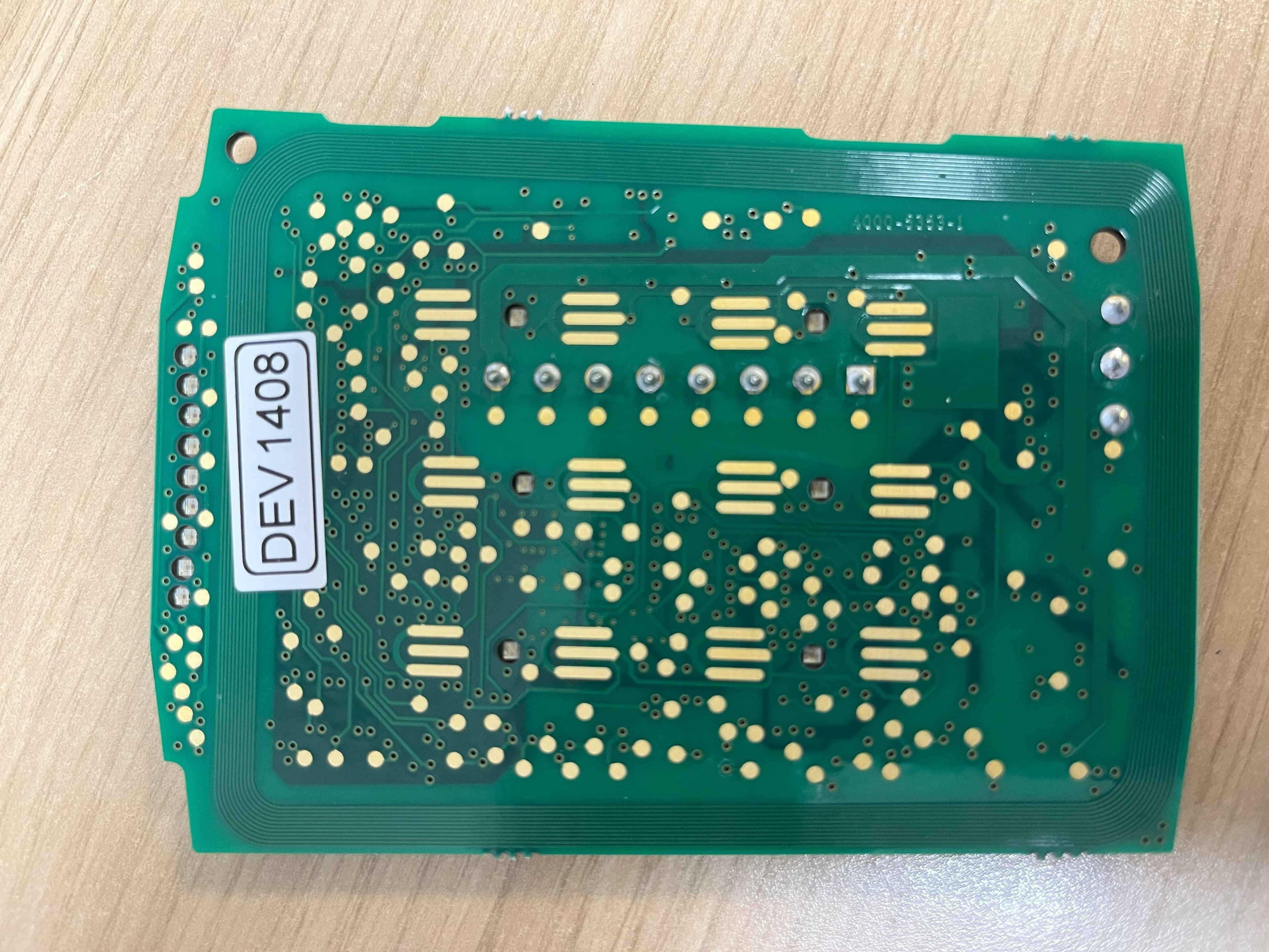
OE5S884OS884O Proximity Reader
G4S Technology Limited
Click to zoom
Application Details
- Equipment Class
- DXX - Part 15 Low Power Communication Device Transmitter
- Date of Grant
- Jan 20, 2020
- Application Purpose
- Original Equipment
- Date of Application
- Jan 19, 2020
- Equipment Note
- S884O Proximity Reader
- Frequency Range
- 13.56000000 - 13.56000000
- Company
- G4S Technology Limited
- Country
- United Kingdom
Documents & Files
Document Text
Text extracted from the exhibit documents filed with the FCC. Open a document above to read the original.
Users Manual
Mount the backplate using countersunk headed screws adjacent to the opening edge of the door. If fixing hole ’A’ is used then the breakout must be removed and the screw must not protrude. Feed the required cables through the backplate: ∑The cable from the controller. If wall tamper function is to be used then breakout ‘B’ must be removed and an appropriate wall screw fitted through the hole to actuate the tamper lever. 2 1 Mount the Backplate Reader Connections The S884-OSDP reader is a keypad. The reader is configured for RS485 / OSDP communications. This reader is for indoor Use Only. The S884-OSDP reader will read smartMAX encoded MIFARE cards and card serial numbers from most ISO 14443A smart cards which have a 4-byte UID (User Identification). For additional information regarding the installation, configuration and proper use of this product: SMS User Guide, P/N 9600-0429, M2150 Access Control Design Guide, P/N 9600-0420, M2150 Intrusion Guide, P/N 9600-0540, M4000 Commissioning Guide contactless smart-card reader, with Graphic LCD and , P/N 9600-0698 The securing screws ‘C’ are integral to the backplate and are unscrewed via the small holes in the enclosure so that the screw heads locate in the counterbored holes on the inside of the enclosure. You should find that the backplate has holes for connection to most standard electrical backboxes. C A B Installation and User Instructions for S884 OSDP Readers 0V Rx+ Rx- 12V Controller 0V 0s +V RS485 (OSDP) 1s Reader TB1 Connect shield at controller end only. Slide the ferrite sleeve onto cable before wiring terminal block. Ferrite to be placed 50mm (2") up cable and held in place with cable ties. Note: The FERRITE must be fitted! Note: 1). Consult local AHJ (Authority Having Jurisdiction) when installing access control readers and locking mechanisms to any portal in an egress path. 2). The use of Fail Closed / secure configuration shall be determined by local building codes and the local AHJ. 3). Wiring methods shall be in accordance with NEC (National Electrical Code) ANSI/NFPA 70. 225ft (75m) max with Belden 9503 or 450ft (150m) by doubling power cores with Belden 9536. If termination is required use Lk5 to set (see over). Twisted pairs Presentthe cardface-ontothereaderuntilyouhear a"bleep". The reader is now working properly. Cardscanbe presented in rapid succession; there is no need, for example, to wait for "UNLOCKED" to disappear before presenting another. If the reader has been enabled for user-code mode at the controller, you can gain access by pressing the O key, entering your card number, then pressing the P key. The reader, by default, retain the formats from the first two cards used. In addition to the card format retention, the readers allow the first two card formats learnt by the reader to be locked. Instructions to 'Lock' the formats: ∑Ensure that the reader has learnt the two required formats. ∑Navigate through the setup menu to 'Card Learning'. ∑Set the 'Card Types Locked' to yes 'Y' and Exit. A Setup menu can be displayed by pressing the O and P keys simultaneously while power is applied. You can use the menu to change the contrast and language used for the LCD (default English). Use the four function keys to navigate around the menu. Please refer to M2150 Intrusion Guide, 9600-0540 for IDS Arm / Disarm procedure. 9600-0725. S884 OSDP Installation and User Instructions Issue 1.2 © AMAG Technology, 2019. FCC Notice: This device complies with Part 15 of the FCC Rules. Operation is subject to the following two conditions: (1) This device may not cause harmful interference, and (2) this device must accept any interference received, including interference that may cause undesired operation. Any unauthorized modification to this device may void the authority of the user to operate it. All trademarks acknowledged. FCC ID: OE5S884O LED Status Indicator GREEN – The lock is released and you may open the door. RED – No access rights to gain entry, or the reader did not read your card properly. Present a card again. YELLOW – Enter your PIN. If you make a mistake, the message INVALID PIN is momentarily displayed, followed by ENTER PIN, to prompt you to try again. Specifications Input voltage: 12-13Vdc. (Voltage Source is Class 2 Power Limited) Input current: 320mA max Operating temperature: 32 to 120°F (0 to 49°C) Operating humidity: 15 to 90%, non-condensing. Maximum read range: 4" (100mm). Approvals En302291 & EN301489 4 Using / Testing the Reader For OSDP the links should be configured as below.: LK3 S(USER Keypad audio feedback) to 1 for sound ON, or 0 for sound OFF. LK5 Fit et link to Pin 2 and 3 to add comms termination (120R). Fit link to Pin1 and 2 for no termination. 3 Reader Links
Cover Letter(s)
-Letter of Authorization - Date: 15 January 2020 Re: Letter of Authorization TO WHOM IT MAY CONCERN We, G4S Technology ltd. hereby declare that company: Name: AMAG Technology ltd. Address: Challenge House, International Drive Tewkesbury Gloucestershire GL20 8UQ and their associates have been authorized to act on our behalf for all acts relating to the global approval/declaration certification of the following product(s) in the United States: FCC ID: OE5S884O Product Name: S8840 Javelin OSDP Reader Sincerely, Printed name: Howard Johnson Signature: Job Title: Chief Operating Officer Company Name: G4S Technology Itd.
Test Report
RF914 6.0 Report on the Radio Testing For G4S Technology Ltd T/AS AMAG Technology on S884-OSDP Reader Report no. TRA-048435-47-00A 28 November 2019 RF914 6.0 REPORT ON THE RADIO TESTING OF A G4S Technology Ltd T/AS AMAG Technology S884-OSDP Reader WITH RESPECT TO SPECIFICATION FCC 47CFR 15.225 TEST DATE: 2019-11-18 to 2019-11-22 Tested b y: D Moncayola Radio Test Engineer Approved by: J Charters Lab Manager Date: 28 November 2019 Disclaimers: [1] THIS DOCUMENT MAY BE REPRODUCED ONLY IN ITS ENTIRETY AND WITHOUT CHANGE [2] THE RESULTS CONTAINED IN THIS DOCUMENT RELATE ONLY TO THE ITEM(S) TESTED Report Number: TRA-048435-47-00A Issue: A Report Number: TRA-048435-47-00A RF914 6.0 Page 3 of 37 1 Revision Record Issue Number Issue Date Revision History A 28 November 2019 Original Report Number: TRA-048435-47-00A RF914 6.0 Page 4 of 37 2 Summary TEST REPORT NUMBER: TRA-048435-47-00A WORKS ORDER NUMBER: TRA-048435-01 PURPOSE OF TEST: USA: Testing of radio frequency equipment per the relevant authorization procedure of chapter 47 of CFR (code of federal regulations) Part 2, subpart J. TEST SPECIFICATION(S): 47CFR15.225 EQUIPMENT UNDER TEST (EUT): S884-OSDP Reader FCC IDENTIFIER: OE5S884O EUT SERIAL NUMBER: 1942001212 MANUFACTURER/AGENT: G4S Technology Ltd T/AS AMAG Technology ADDRESS: Challenge House International Drive Tewkesbury Gloucestershire GL20 8UQ United Kingdom CLIENT CONTACT: Ian Williams 01684 850977 [email protected] ORDER NUMBER: PUR140801 TEST DATE: 2019-11-18 to 2019-11-22 TESTED BY: D Moncayola Element Report Number: TRA-048435-47-00A RF914 6.0 Page 5 of 37 2.1 Test Summary Test Method and Description Requirement Clause 47CFR15 Applicable to this equipment Result / Note Radiated spurious emissions, below 30 MHz 15.225(d) Pass Radiated spurious emissions 15.209 Pass AC power line conducted emissions 15.207 Pass Occupied bandwidth 15.215(c) Pass Field strength of fundamental 15.225(a), (b) and (c) Pass Frequency stability 15.225(e) Pass Notes: The results contained in this report relate only to the items tested, in the condition at time of test, and were obtained in the period between the date of initial receipt of samples and the date of issue of the report. The apparatus was set up and exercised using the configurations, modes of operation and arrangements defined in this report only. Any modifications made are identified in Section 8 of this report. Particular operating modes, apparatus monitoring methods and performance criteria required by the standards tested to have been performed except where identified in Section 5.2 of this test report (Deviations from Test Standards). Report Number: TRA-048435-47-00A RF914 6.0 Page 6 of 37 3 Contents 1 Revision Record ............................................................................................................................... 3 2 Summary .......................................................................................................................................... 4 2.1 Test Summary ......................................................................................................................................... 5 3 Contents ........................................................................................................................................... 6 4 Introduction ....................................................................................................................................... 8 5 Test Specifications ........................................................................................................................... 9 5.1 Normative References ............................................................................................................................. 9 5.2 Deviations from Test Standards .............................................................................................................. 9 6 Glossary of Terms .......................................................................................................................... 10 7 Equipment Under Test .................................................................................................................... 11 7.1 EUT Identification .................................................................................................................................. 11 7.2 System Equipment ................................................................................................................................. 11 7.3 EUT Mode of Operation ......................................................................................................................... 11 7.3.1 Transmission ................................................................................................................................. 11 7.4 EUT Radio Parameters .......................................................................................................................... 11 7.4.1 General .......................................................................................................................................... 11 7.5 EUT Description .................................................................................................................................... 11 8 Modifications ................................................................................................................................... 12 9 EUT Test Setup .............................................................................................................................. 12 9.1 Block Diagram ....................................................................................................................................... 12 9.2 General Set-up Photograph ................................................................................................................... 12 9.3 Measurement software ........................................................................................…
Text truncated - open the document above for the full version.
Contact Information
Applicant
ANDY WATTS(Mr)
Test Firm
Element Materials Technology Warwick LtdKeith Wright
Technical Specifications
| # | Rule Parts | Frequency Range | Power Output |
|---|---|---|---|
| 1 | 15C | 13.56 MHz - 13.56 MHz | - |
Other Applications from G4S Technology Limited
OE5S870C
Dec 22, 2025Proximity card reader with keypad for access control systems
Equipment Class
DCD - Part 15 Low Power Transmitter Below 1705 kHz
OE5S884C
Dec 22, 2025Access Control Keypad Reader 884 MKII
Equipment Class
DXX - Part 15 Low Power Communication Device Transmitter
OE5S874C
Dec 19, 2025Smartcard reader with keypad for access control systems 874 MKII
Equipment Class
DXX - Part 15 Low Power Communication Device Transmitter
OE5S680A
Nov 19, 2013S680 Proximity Card Reader
Equipment Class
DXX - Part 15 Low Power Communication Device Transmitter
OE5S884B
Aug 02, 2013S884B Proximity Reader
Equipment Class
DXX - Part 15 Low Power Communication Device Transmitter