OG4-BC74Pushbutton TX
Akerstroms Bjorbo AB
Click to zoom
Application Details
- Equipment Class
- TNT - Licensed Non-Broadcast Transmitter Worn on Body
- Date of Grant
- Jun 24, 2003
- Application Purpose
- Original Equipment
- Date of Application
- Jun 24, 2003
- Equipment Note
- Pushbutton TX
- Frequency Range
- 433.87500000 - 434.65000000
- Company
- Akerstroms Bjorbo AB
- Country
- Sweden
Documents & Files
Document Text
Text extracted from the exhibit documents filed with the FCC. Open a document above to read the original.
Users Manual
DRIVING INSTRUCTION REMOTUS BC7400 MANUAL BC7400 No. 926137-000 Version: A0 Approved by: TB Page 1 (8) MANUAL BC7400 No. 926137-000 Version: A0 Approved by: TB Page 2 (8) TRANSMITTER ON Pull out the stop button and the transmitter is switched on. The operation indicator lamp (STATUS) starts blinking and the transmitter is on. MAIN CONTACTOR ON Then the transmitter is on press the Å. This actuates the Main Contactor in the receiver (the Main Contactor of the telpher) and the telpher is ready for operation. NORMAL RUN The transmitter is designed with two pushbuttons for UP/DOWN and two for FORWARD/BACKWARD. Each button is divided into 2 steps (a perceptible resistance) which facilitates the running at a certain speed. The first speed is obtained when the pushbutton is half compressed and the second speed is obtained when the pushbutton is totally compressed. All the motions can be run simultaneously and the motions stop when the pushbutton is released, otherwise make an EMERGENCY STOP. MANUAL BC7400 No. 926137-000 Version: A0 Approved by: TB Page 3 (8) MICRO RUN Push in the button for MICRO and the diode lamp for micro lights. The micro-run movements are only at lowest speed in micro-run mode irrespective of the compression of the pushbuttons. The buttons are looped so that only one movement can be operated at a time. The other functions are work as in ordinary runs. PUSHBUTTON 1 AND 2 The diode lamps indicate which function who has been chosen. The pushbutton function can be momentary (the function will be active as long as the pushbutton is activated) or maintain (the function is active when the diode lamp lights). See the installation guide how to choose the function of the pushbuttons. SIGNAL A signal can be emitted at any time during the run and is obtained as long as the push button switch is depressed. EMERGENCY STOP Depress the STOP button for Emergency STOP. MANUAL BC7400 No. 926137-000 Version: A0 Approved by: TB Page 4 (8) AUTOMATIC SWITCH OFF FUNCTION The transmitter is equipped with automatic switch-off function, switching off the transmitter after 2, 5, or 15 minutes after the latest use depending on what period of time has been looped. It is also possible to loop for continuous drive. The indicator lamp for operation goes out and the Main Contactor is de-energized. For renewed activation of the Main contactor restart is required, press the stop button, pull it out again and press the Å. When the battery voltage is to low, that also causes automatic switch-off. TRANSMITTER OFF MAIN CONTACTOR OFF Depress the STOP button which switches off the transmitter. At the same time the Main Contactor is deactivated (the Main Contactor of the telpher cuts out).The operation indicator lamp goes out. RUN DOWN BATTERY The transmitter is equipped with an indicator lamp for battery status (STATUS). The lamp blinks slowly when the battery voltage is normal, but starts to blink rapidly when it falls. When the indicator lamp has started blinking rapidly the transmitter can be operated for approx. 10 min. before the voltage is so low that the transmitter switches off automatically. MANUAL BC7400 No. 926137-000 Version: A0 Approved by: TB Page 5 (8) CHARGING INSTRUCTIONS • The transmitter should be set on charge as often as possible. • The battery has got power for 10 hours continuous operation. • Charging time 3 hours (quick-charge) there upon automatically changes to maintenance charging which does not need supervising. • The transmitter has a indicator lamp (CHARGE) which lights when the battery is charging. When the charging is ready, the lamp goes out. • A WELL MAINTAINED BATTERY IS NECESSARY FOR FAULTLESS OPERATION. • WATCH THE ACCUMULATED CHARGE AND CHARGING CAREFULLY. • THE BATTERY DID NOT BE CHARGED IF ITS TEMPERATURE IS LOWER THAN ±0°C OR HIGHER THAN +45°C. MANUAL BC7400 No. 926137-000 Version: 0 Approved by: TB Page 6 (8) ! INSTRUCTIONS FOR CRANE OPERATORS These instructions have to be followed. Marked 1. Check that the radiotransmitter operates on the crane which you are going to drive (ex. give a signal). Check the function of the radiotransmitter. 2. Check that no unauthorized person is on or at the crane when you start to drive it. The blocking device at entry of the crane should be closed. 3. Check the position of the symbols for driving direction (crane-trolley travel). 4. At the beginning of each shift the crane operator is to test brake, limit-switches and emergency stop function. 5. The crane operator is when driving the crane to walk or stand at a suitable distance from the crane hoist in order to have adequate overview of the operation. 6. It is prohibited to move the crane load over oneself or other people. Signal in order to warn others. 7. Avoid driving into end stops since equipment and goods can be damaged. 8. Check your own free passageway in order to avoid tripping over material on the ground when you drive the crane Keep the workplace in good order. 9. If you loose control of the crane movements, release the pushbuttons in order to stop the crane. If still it does not stop, actuate the STOP function. MANUAL BC7400 No. 926137-000 Version: A0 Approved by: TB Page 7 (8) 10. Find out where the crane's main power disconnector is in order to be able to quickly switch off if required. 11. Never hand over the transmitter to anybody who has not got through training in radio-control crane operation. 12. After completed operation you should always switch the transmitter off with STOP. Note! Do never put the transmitter aside without switching the transmitter off with STOP. 13. The main contactor of the crane is to be switched off after end of working hours. The transmitter is then to be kept inaccessible to unauthorized persons. 14. In case of faults or breakdowns in the radiocontrol equipment the crane should permit operating from the cab or with suspended operating gear. In such case first turn the switch from radio operation to manual operation. Make certain how this switch-o…
Text truncated - open the document above for the full version.
Cover Letter(s)
Request for Confidentiality 22 May 2003 PHOENIX TEST-LAB GmbH Königswinkel 10 D32825 Blomberg Germany RE: Certification Application FCC ID: OG4-BC74 Please be advised that the following information is to be held confidential on behalf of Akerströms Björbo AB: • Schematics • Parts Lists • Block Diagram The application contains technical information which Akerströms Björbo AB deems to be trade secrets and proprietary. If made public, the information might be used to the disadvantage of the applicant in the market place. Thank you for your attention to this matter. Signatory
Cover Letter(s)
30090-3 FCC ID: OG4-BC74 Answers to ATCB comments (Email from Timothy Johnson - June 6, 2003): 1 New file uploaded 2 The frequency range of CDP-TX-02N module is 433.875 MHz up to 434.650 MHz (see uploaded data sheets). The printing on the label (433 MHz) is only for operating band information. The change of channel is only available by manufacturer not for the customer (because dip switches are on the bottom side of the module.) The selected channel is a manufacturer default setting (434.650 MHz). 3 There are no different RF modules used (explained at pt. 2) 4 New file uploaded Note: Parts lists are only available in Japanese language! - New file uploaded 5 New file uploaded 6 6a: Voltage: 2V / Current: approx. 15mA 6b: see attached description from module manufacturer (pt.2) 6c: see attached description from module manufacturer (pt.2) 7 New file uploaded 8 New file uploaded 9 New file uploaded
External Photos
FCC ID: OG4-BC74 External Photos Page 1 of 5 Front view of EUT FCC ID: OG4-BC74 External Photos Page 2 of 5 Right view of EUT FCC ID: OG4-BC74 External Photos Page 3 of 5 Left view of EUT FCC ID: OG4-BC74 External Photos Page 4 of 5 Top view of EUT FCC ID: OG4-BC74 External Photos Page 5 of 5 Bottom view of EUT
ID Label/Location Info
FCC ID: OG4 - BC74
Internal Photos
FCC ID: OG4-BC74 Internal Photos Page 1 of 5 Case opened FCC ID: OG4-BC74 Internal Photos Page 2 of 5 EUT disassembled FCC ID: OG4-BC74 Internal Photos Page 3 of 5 PCB bottom view FCC ID: OG4-BC74 Internal Photos Page 4 of 5 PCB top view FCC ID: OG4-BC74 Internal Photos Page 5 of 5 Right view of EUT
Operational Description
7557-1 Hotaka,Hotaka-machi,Minamiazumi,Nagano 399-8303,Japan Tel:+81-263-82-1024 Fax:+81+263-82-1016 http://www.circuitdesign.co.jp/ CDP-TX/RX-02NDS ver1.0 CIRCUIT DESIGN, INC. International Business Division Feature Application Remote control systems Security systems Alarms Telemetry systems European EN300-220 compliance 32 frequency synthesized RF channels 5mW/10mW selectable Low voltage operation High sensitivity 300m range FM narrow band modulation and high frequency stability Common Item Communication form Oscillation system Frequency range Number of RF channels Channel step Frequency stability Baud rate Operating temp. range Transmitter type RF output power Transmitter start up time Modulation Data input level Input signal Deviation Spurious emission Adjacent channel power Supply voltage Supply current Dimensions Weight Receiver type Sensitivity Selectivity Demodulation Distortion S/N ratio Data output Supply Voltage Supply current Dimensions Weight Specification One way PLL controlled VCO 433.875MHz to 434.650MHz 32 ch 25kHz +/-2.5kHz (-10 to +55 degree C) 300 to 4800bps -10 - +60 degree C PLL synthesizer 10mW/5mW 80msec FM Narrow 2.2 - 12V Digital 2.0kHz <-60dBm (< 862MHz) , <-46dBm ( >= 862MHz) <200nW 2.4 - 12V DC 30mA (typ) 36 X 26 X 10 mm 12.5g Double Superheterodyne PLL synthesizer -120dBm (12dB/SINAD at CCITT filter) +/-7.5kHz at -6dB point FM Narrow <3% at 1kHz 35dB overall (AF out) Digital 3.6 to 12V DC 26mA (typ) 50 X 30 X 9mm 19g UHF Narrow Band Multi Channel Transmitter/Receiver CDP-TX-02N/ CDP-RX-02N The unique and compact CDP-02N is a frequency selectable radio data module for 434MHz UHF band. Both CDP-TX-02N (transmitter) and CDP-RX-02N (receiver) are equipped by frequency synthesizer system with microprocessor. Frequency range of CDP-02N is from 433.875MHz to 434.650MHz in 32 channels which are selectable by the use of an onboard 4 bits switch. Small size, low voltage operation and frequency selectability of CDP-02N make it ideal for various applications in sites where many radio transmitters are operated. CDP-TX-02N (Transmitter) CDP-RX-02N (Receiver) Specifications are subject to change without prior notice CIRCUIT DESIGN, INC. CDP-02N UHF Synthesized Radio Data Module Operation Guide 1 C C D D P P - - 0 0 2 2 N N CDP-TX-02N& CDP-RX-02N (433MHz) CDP-TX-02AN& CDP-RX-02AN (458MHz) UHF FM-NARROW BAND SYNTHESIZED RADIO DATA MODULE Operation Guide Version 1.4 (July, 2002) CIRCUIT DESIGN, INC., International Business Division 7557-1 Hotaka, Hotaka-machi, Minamiazumi, Nagano 399-8303. JAPAN Tel: + +(0263)-82-1024 Fax: + +(0263)-82-1016 CIRCUIT DESIGN, INC. CDP-02N UHF Synthesized Radio Data Module Operation Guide 2 CONTENTS GENERAL DESCRIPTION & FEATURES ................................ 3 CDP-TX-02N transmitter module ....................................... 4 CDP-RX-02N receiver module ........................................... 4 OPERATION INSTRUCTIONS ................................................... 6 Supply voltage ..................................................................... 6 Data input ............................................................................ 6 Data format .......................................................................... 7 Channel and frequency setting ............................................ 7 Outputs ................................................................................. 8 Test Set ECB-03 and DCB-03 .............................................. 8 Antennas .............................................................................. 8 Start up.................................................................................. 9 SPECIFICATIONS ...................................................................... 10 CHANNEL AND FREQUENCY SETTING .............................. 11 BLOCK DIAGRAM ................................................................... 13 DIMENSIONS ............................................................................ 14 DATA .......................................................................................... 15 IMPORTANT NOTICE .............................................................. 16 CAUTION & WARNING DIMENSIONS ................................. 16 CIRCUIT DESIGN, INC. CDP-02N UHF Synthesized Radio Data Module Operation Guide 3 GENERAL DESCRIPTION & FEATURES Features • Compatible with European EN 300 220 standard • Very small compact integrated device with PLL synthesizer and micro controller • Frequency selection free in 32 channels for 433MHz, 11 channels for 458MHz • New integrated UHF filter technology • 5mW/10mW selectable Applications • Radio remote control cranes and machines • Radio remote control for garage door controls • Security systems • Room surveillance • Theft protection • Telemetry systems General description The CDP-02N consists of CDP-TX-02N (CDP-TX-02AN) transmitter and CDP-RX-02N (CDP-RX-02AN) receiver. It is suitable for various application fields such as wireless data communication, remote control, telemetry or wireless security systems. It is easy to use and integrate into application systems. The CDP-02N is equipped with a frequency synthesizer system with micro controller. The frequency range of the CDP-02N (EU type) is from 433.875MHz to 434.650MHz in 32 channels which are selectable by use of a 4 bits switch, and a jumper on the PCB for 2 groups of 16 channels. The frequency range of the CDP-02AN (UK type) is from 458.525MHz to 458.775MHz in 11 channels, which are selectable with a 4 bits switch. The compact size, low operation voltage and frequency selectability of the CDP-02N make it ideal for various applications where its interference rejection and practical distance range is far better than similar RF modules based on wide band SAW-resonator frequency generators. Standard RS232 serial data and other digital data (TTL level), such as pulse width modulation signals and signals from standard encoder-decoder circuits of the given AF bandw…
Text truncated - open the document above for the full version.
Operational Description
780 45 Björbo • Tel 0241-250 00 • Fax 0241-232 90 • www.akerstroms.com • Email [email protected] The RemotusThe Remotus The RemotusThe Remotus The Remotus Mini systemMini system Mini systemMini system Mini system The Mini system is preprogrammed to enable short delivery times. Mini is userfriendly and is aimed as a control- ler for telphers and small machinerys. The system consists of a small pushbutton transmitter, a receiver and a charger. Key FeaturesKey Features Key FeaturesKey Features Key Features TransmitterTransmitter TransmitterTransmitter Transmitter Small and rugged handy transmitter with 4 doubleaction and 4 singleaction pushbuttons. LED indications for Battery, status and selected functions. An accompained attach- ment-clips may be mounted on the transmitter. Inbuilt self- diagnostic continously checks important functions. Dimensions 142x68x26 mm ReceiverReceiver ReceiverReceiver Receiver 8 output relays with changeover contacts. Different pre- programmed functions may be selected by a rotary switch. Frequency synthesized radio with selectable frequencies in the 433 MHz band. Dual channel approach (two separate microprocessors) enables high safety. An antenna is mounted directly on the receiver. IP 65 Output data250VAC; 6A resistive load Power supply Max 12 VA Voltage supply 24/48/115/230 +15 –20% VAC alt. 15-35 VDC Dimensions250x150x80 mm Battery/ChargerBattery/Charger Battery/ChargerBattery/Charger Battery/Charger The transmitter has an inbuilt Li-Ion-battery which gives approx. 10 hours of continous operation. The battery is charged via an inbuilt charger. An AC-adapter is included for battery-charging. OtherOther OtherOther Other Two signs, ”Radio-controlled crane” and ”When working on the crane...” are included in each system delivery. Installation- instructions and usermanual are included to enable a flexible assembly and easily understood handling. As options an inbuilt siren or a relayboard for an external siren, is available. A cassette for the transmitter is also available. The transmitter built in battery may be charged when the transmitter is put in the cassette.
Test Report
Page 1 of 34 Pages Straubing, May 2, 2003 T E S T - R E P O R T No. 56502-30090-3 for Remotus BC 7418 Portable Remote Control Transmitter Applicant: Akerstrˆms Bjˆrbo AB Purpose of testing: To show compliance with FCC Code of Federal Regulations, CFR 47, Part 90, Section 90.217 FCC Code of Federal Regulations, CFR 47, Part 2, Subpart J Note: The test data of this report relate only to the individual item which has been tested. This report shall not be reproduced except in full extent without the written approval of the testing laboratory. EMV-Pr ̧fzentrum EMI/EMC-Testcenter EMV-Pr ̧fzentrum EMI/EMC-Testcenter FCC-ID: OG4-BC74 Test Report No. 56502-30090-3 Page 2 of 34 Pages Table of Contents 1. Administrative Data ............................................................................................. 3 2. Identification of Test Laboratory .......................................................................... 4 3. Summary of Test Results .................................................................................... 5 4. Operation Mode of EUT....................................................................................... 6 5. Configuration of EUT and Peripheral Devices ..................................................... 7 6. Measuring Methods ............................................................................................. 8 6.1. Maximum Transmitter Power (CFR47 ß90.217, ß2.1046 ) ............................ 8 6.2. Frequency tolerance (CFR47 ß90.217, ß2.1055 )....................................... 10 6.3. Occupied Bandwidth (CFR47 ß90.217, ß2.1049)........................................ 12 6.4. Unwanted Emission (CFR47 ß90.217, ß2.1051) ......................................... 13 7. Photographs of Test Setups .............................................................................. 15 8. Equipment List................................................................................................... 18 9. Referenced Regulations .................................................................................... 20 10. List of Measurements ........................................................................................ 21 11. Test Results ...................................................................................................... 22 12. Additional Information supplementary to the Test Report .................................. 33 12.1. Calculation of the necessary bandwidth (Section 2.202b)........................... 33 12.2. Additional Information ................................................................................. 34 EMV-Pr ̧fzentrum EMI/EMC-Testcenter FCC-ID: OG4-BC74 Test Report No. 56502-30090-3 Page 3 of 34 Pages 1. Administrative Data Equipment Under Test (EUT): Remotus BC 7418 Serial number(s): 92 6116-0605 Type of equipment: Portable Remote Control Transmitter Type of emission: 8K80F1D Parts/accessories: --- FCC-ID: OG4-BC74 Applicant: (full address) Akerstrˆms Bjˆrbo AB 78045 Bjˆrbo, SWEDEN Contract identification: --- Contact person: Mr. Bernt Eriksson Manufacturer: Akerstrˆms Bjˆrbo AB Receipt of EUT: 17 February 2003 Dates of test: February to April 2003 Note: --- Responsible for testing: Thomas Eberl Responsible for test report: Thomas Eberl EMV-Pr ̧fzentrum EMI/EMC-Testcenter FCC-ID: OG4-BC74 Test Report No. 56502-30090-3 Page 4 of 34 Pages 2. Identification of Test Laboratory Test Laboratory: Senton GmbH EMI/EMC Test Center (full address): Aeussere Fruehlingstrasse 45 D-94315 Straubing Germany Contact person: Mr. Johann Roidt Communication: Telephone (+49) 0 94 21 / 55 22-0 Fax (+49) 0 94 21 / 55 22-99 eMail: [email protected] FCC registration number: 90926 EMV-Pr ̧fzentrum EMI/EMC-Testcenter FCC-ID: OG4-BC74 Test Report No. 56502-30090-3 Page 5 of 34 Pages 3. Summary of Test Results The tested sample complies with the requirements set forth in the The Code of Federal Regulations 47, Part 90, Section 90.217 and The Code of Federal Regulations 47 Part 2, Subpart J. of the Federal Communication Commission (FCC) Johann Roidt Thomas Eberl Laboratory Manager Test Engineer EMV-Pr ̧fzentrum EMI/EMC-Testcenter FCC-ID: OG4-BC74 Test Report No. 56502-30090-3 Page 6 of 34 Pages 4. Operation Mode of EUT • transmitting continuously 1 • with battery supply nominal 3,7 V DC 2 • operating with f = 434,648 MHz 1 Modulation as indicated on appropriate test record 2 For conducted measurements replaced by external DC supply EMV-Pr ̧fzentrum EMI/EMC-Testcenter FCC-ID: OG4-BC74 Test Report No. 56502-30090-3 Page 7 of 34 Pages 5. Configuration of EUT and Peripheral Devices EUT is configured as stand-alone device Configuration of cables of EUT Not applicable Configuration of peripheral devices connected to EUT Not applicable EMV-Pr ̧fzentrum EMI/EMC-Testcenter FCC-ID: OG4-BC74 Test Report No. 56502-30090-3 Page 8 of 34 Pages 6. Measuring Methods 6.1. Maximum Transmitter Power (CFR47 ß90.217, ß2.1046 ) The maximum transmitter power was measured radiated and, if applcable, conducted at antenna connector. EMV-Pr ̧fzentrum EMI/EMC-Testcenter FCC-ID: OG4-BC74 Test Report No. 56502-30090-3 Page 9 of 34 Pages 6.1.1. Radiated Maximum Transmitter Power Radiated Maximum Transmitter Power was measured with detector-function of the spectrum analyzer set to positive peak and trace mode max hold: RBW = 100 kHz, VBW = 100 kHz, span = 1 MHz, sweep = 15 s For measurement setup and procedure see section "Unwanted Emission " on Page 13. EMV-Pr ̧fzentrum EMI/EMC-Testcenter FCC-ID: OG4-BC74 Test Report No. 56502-30090-3 Page 10 of 34 Pages 6.2. Frequency tolerance (CFR47 ß90.217, ß2.1055 ) 6.2.1. Frequency stability vs. temperature The frequency stability vs. temperature was measured with a spectrum analyzer connected to the antenna connector (conducted measurement) while EUT was operating in transmit mode using the assigned frequency. The trace mode of the spectrum analyzer was set to write with frequency count mode activated: RBW = 100 Hz, VBW…
Text truncated - open the document above for the full version.
Test Setup Photos
EMV-Pr ̧fzentrum EMI/EMC-Testcenter FCC-ID: OG4-BC74 Test Report No. 56502-30090-3 Page 16 of 34 Pages Test setup for radiated unwanted radiation 30 MHz - 4.5 GHz EMV-Pr ̧fzentrum EMI/EMC-Testcenter FCC-ID: OG4-BC74 Test Report No. 56502-30090-3 Page 17 of 34 Pages Test setup for radiated unwanted radiation 30 MHz - 4.5 GHz (continued)
Contact Information
Applicant
Lars-Olov Liss(VD/President)
Technical Contact
Senton GmbHJohann Roidt
[email protected]+49 9421 55 22 13
Aeussere Fruehlingstrasse 45 · Straubing · Germany
Non-Technical Contact
Senton GmbHJohann Roidt
[email protected]+49 9421 55 22 13
Test Firm
TUV SUD Product Service GmbH PS-EMC-STRRainer Heller
Technical Specifications
| # | Rule Parts | Frequency Range | Power Output | Emission | Tolerance |
|---|---|---|---|---|---|
| 1 | 90.217(b) | 433.875 MHz - 434.65 MHz | 400.00 µW | 8K80F1D | 3.5900000000 ppm |
Other Applications from Akerstroms Bjorbo AB

OG4-TRXBQ900
Dec 16, 2012Radio module TRX BQ900
Equipment Class
DXX - Part 15 Low Power Communication Device Transmitter
OG4-K3
Jun 05, 2012Sesam 800 Radio Remote Control
Equipment Class
DXX - Part 15 Low Power Communication Device Transmitter
OG4-RXDIN
Jun 04, 2012Sesam 800 Remote Radio Control
Equipment Class
DXX - Part 15 Low Power Communication Device Transmitter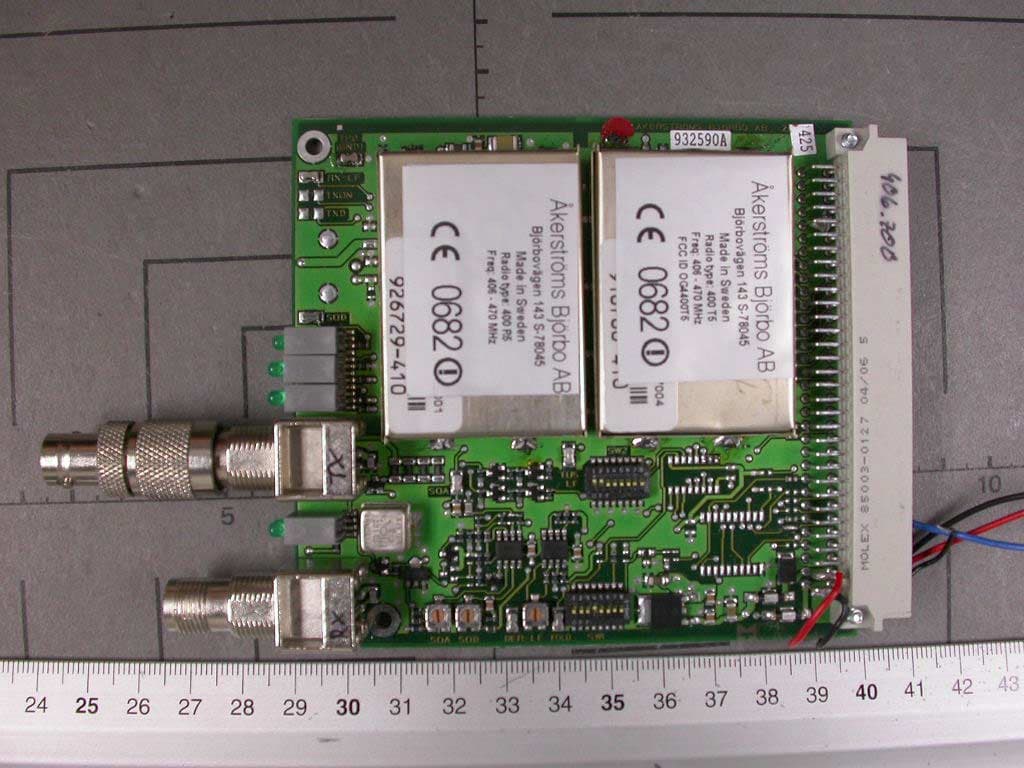
OG4400T5
Apr 26, 2005Remote Control Transmitter Module
Equipment Class
TNB - Licensed Non-Broadcast Station Transmitter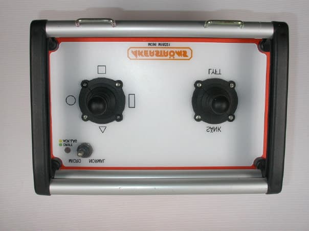
OG4MC96
Jun 22, 2004Remote Control Transmitter
Equipment Class
TNT - Licensed Non-Broadcast Transmitter Worn on Body