OG4-MC96Remote Control Transceiver
Akerstroms Bjorbo AB
Click to zoom
Application Details
- Equipment Class
- TNT - Licensed Non-Broadcast Transmitter Worn on Body
- Date of Grant
- Jun 29, 2003
- Application Purpose
- Original Equipment
- Date of Application
- Jun 29, 2003
- Equipment Note
- Remote Control Transceiver
- Frequency Range
- 467.83750000 - 467.83750000
- Company
- Akerstroms Bjorbo AB
- Country
- Sweden
Documents & Files
Document Text
Text extracted from the exhibit documents filed with the FCC. Open a document above to read the original.
Users Manual
MANUAL MC9600 Del. no. Ver. A0 Approved by: Sheet 1 (9) DRIVING INSTRUCTION REMOTUS MC9600 Customer: Crane No: Delivery No: 910 ID Code: 10 Frequency: MHz Del. Date: W03 MANUAL MC9600 Del. no. Ver. A0 Approved by: Sheet 2 (9) MANUAL MC9600 Del. no. Ver. A0 Approved by: Sheet 3 (9) TRANSMITTER ON Pull out the stop button (EMERGENCY STOP) and the transmitter will make a self-test during 0,5 seconds. The operation indicator lamp starts blinking and the transmitter is on. MAIN CONTACTOR ON Then the transmitter is on press the signal button and this actuates the Main Contactor in the receiver and the traverse is ready for operation. NORMAL RUN The transmitter is designed with two manipulators: One for Bridge/Trolley travel and the other for Hoist motions, each direction being divided into 2 or 4 steps (a perceptible resistance) facilitating run at a certain speed. The size and direction of the manipulators deflections are equal to the speed and direction of the objects motions. Two motions can be run simultaneously in the same manipulator. The motions stop when the manipulator is brought to neutral, otherwise push the STOP. MANUAL MC9600 Del. no. Ver. A0 Approved by: Sheet 4 (9) MICRO RUN (NOT SIMULTANEOUS) Set the selector for MICRO/NORMAL in position MICRO. The micro-run movements are only at lowest speed in micro-run mode irrespective of the deflections of the manipulator. The other functions are working just as in ordinary runs. The manipulated movements are looped so that only one movement can be operated at a time. DUPLEX The transmitter is the master in a duplex system. After every sent message the transmitter requests an answer from the receiver. The answer is shown on the display as a numerical value alternatively as a diode lamp indication. Updating is made 22 times/second. SIGNAL A signal can be emitted at any time during the run and is obtained as long as the push button switch is depressed. STOP Depress the STOP button for STOP. MANUAL MC9600 Del. no. Ver. A0 Approved by: Sheet 5 (9) AUTOMATIC SWITCH- OFF FUNCTION The transmitter is equipped with automatic switch-off function, switching off the transmitter after 2, 5, or 15 minutes. After the latest use, depending on what period of time has been looped, it is also possible to loop for continuous drive. The indicator lamp for operation goes out and the Main Contactor is de-energized. For renewed activation of the Main contactor restart is required, press the stop button and pull it out again, and push the signal button. Battery voltage below 5,4 V also causes automatic switch-off. TRANSMITTER OFF MAIN CONTACTOR OFF Depress the STOP button which switches off the transmitter. At the same time the Main Contactor is deactivated (the Main Contactor of the traverse cuts out). The operation indicator lamp goes out. MANUAL MC9600 Del. no. Ver. A0 Approved by: Sheet 6 (9) TRANSMITTER LED INDICATIONS If the transmitter under start up or under drift detect a fault in any self tests it will indicates with a continuously red light. After what the transmitter closed down. If it indicates continuously yellow light when you start up the transmitter it will be something fault with some of the manipulators. INDICATIONS EXPLANATIONS Green flashing Drift Yellow flashing Battery voltage low < 5,9 V Yellow continuously Discharge battery voltage < 5,4 V Red continuously Fault, see the service manual RUN DOWN BATTERY The transmitter is equipped with an indicator lamp (green and yellow) for battery status. The lamp blinks green when the battery voltage is normal (=6V), but starts to blink yellow when it falls (<5,9V). When the indicator lamp has started blinking yellow the transmitter can be operated, but the battery will be changed, before the voltage is so low (<5,4V) that the transmitter switches off automatically. This is indicated by the indicator lamp showing fixed yellow light. The two last-mentioned statuses are also present at outlets in the receiver. MANUAL MC9600 Del. no. Ver. A0 Approved by: Sheet 7 (9) CHARGING INSTRUCTIONS ∗ The battery has got power for 10 hours continuous operation. ∗ Charging time 1,5 hours (quick-charge) there upon changes to maintenance charging which does not need supervising. ∗ The charging device has LED indication for quick charge (fixed red LED) or maintenance charge (flashing red LED). ∗ Take the battery out of the charger before the main-connection is disconnect. ∗ A WELL MAINTAINED BATTERY IS NECESSARY FOR FAULTLESS OPERATION ∗ WATCH THE BATTERY CHARGE AND CHARGING CAREFULLY. ∗ THE BATTERY DID NOT BE CHARGED IF ITS TEMPERATURE IS LOWER THAN +10°C OR HIGHER THAN +35°C. MANUAL MC9600 Del. no. Ver. A0 Approved by: Sheet 8 (9) INSTRUCTIONS FOR CRANE OPERATORS These instructions have to be followed. Marked 1. Check that the radio transmitter operates on the crane which you are going to drive. Check the marking. Check the function of the radio transmitter. 2. Check that no unauthorized person is on or at the crane when you start to drive it. The blocking device at entry of the crane should be closed. 3. Check the position of the symbols for driving direction (crane-trolley travel). 4. At the beginning of each shift the crane operator is to test brake, limit switches and emergency stop function. 5. The crane operator is when driving the crane to walk or stand at a suitable distance from the crane hoist in order to have adequate overview of the operation. 6. It is prohibited to move the crane load over oneself or workmates. Signal in order to warn workmates. 7. Avoid driving into end stops since equipment and goods can be damaged. 8. Check your own free passageway in order to avoid tripping over material on the ground when you drive the crane Keep the workplace in good order. ! ! ! ! ! ! ! ! ! MANUAL MC9600 Del. no. Ver. A0 Approved by: Sheet 9 (9) 9. If you loose control of the crane movements, release the pushbuttons to obtain the zero position in order to stop the crane. If still it does not stop, actuate the STOP fu…
Text truncated - open the document above for the full version.
Cover Letter(s)
Request for Confidentiality 22 May 2003 PHOENIX TEST-LAB GmbH Königswinkel 10 D32825 Blomberg Germany RE: Certification Application FCC ID: OG4-MC96 Please be advised that the following information is to be held confidential on behalf of Akerströms Björbo AB: • Schematics • Parts Lists • Block Diagram The application contains technical information which Akerströms Björbo AB deems to be trade secrets and proprietary. If made public, the information might be used to the disadvantage of the applicant in the market place. Thank you for your attention to this matter. Signatory
Cover Letter(s)
30091-3 FCC ID: OG4-MC96 Answers to ATCB comments (Email from Timothy Johnson - June 7, 2003): 1 New file uploaded 2 It is a semi-duplex system, it is only transmitting on one channel. If frequency change required, the internal crystal of the module can be changed only by service personal. The second module placed on the PCB is the receiver module. 3 For the US market only the frequency 467.8375 MHz is required. 4 New file uploaded 5 New file uploaded 6 Referring to pt. 2 7 New file uploaded 8 Is not available 9 New file uploaded 10 Data Tx 100mW ULTRACOM. Current final stage I = 77mA, U = 7.2 V 11 New file uploaded 12 New file uploaded 13 New file uploaded
Cover Letter(s)
30091-3 FCC ID: OG4-MC96 Answers to 2.ATCB comments (Email from Timothy Johnson - June 25, 2003): 1 New files uploaded (Schematics and Parts Lists) 2 3 4 Corrected Test Report uploaded. ITU Designation on page 3 corrected. Page 33 also modified, according your "measurement". The spectrum mask between the two models looks identical. The used TX module is a special customized module - specially made for Akerströms Björbo AB only for this application! The RF output power is limited to max. 100 mW, also the modulation is limited to measured values! About the pin holes in the cover - the adjustment were made at Ultracom company under customized specification. After the adjustment the holes were sealed. The specifications at the Ultracom website for this modules are for standard applications for the European market - not for US.
Cover Letter(s)
American Telecommunications Certification Body Inc. 6731 Whittier Ave, McLean, VA 22101 June 7, 2003 RE: Akerstroms Bjorbo AB FCC ID: OG4-MC96 I have a few comments on the above referenced Application. 1) The FCC Label shows "FCC-ID: OG4-MC96". Note that a dash should not be placed between the words FCC and ID. Please correct to "FCC ID: OG4-MC96". 2) It is not certain the actual transmit frequencies that this device will be capable of transmitting on. Additionally it appears the device may use 2 transmit frequencies simultaneously, one for each channel. Please provide further information regarding actual transmit frequencies. 3) If this device may be built to transmit on different sets of TX frequencies, it is not certain what type of component changes there are to the device. Note that depending on the changes used to cover the 421-512 Frequency range, an investigation may be necessary to determine how the test results vary. 4) Photographs must be provided showing the area underneath the RF shields. 5) The confidentiality letter requests confidentiality on the Technical Description. However the operational description provided appears only to be a sales brochures and therefore not considered as confidential. Please remove the technical description from the confidentiality letter. 6) Please confirm if this device transmits at two different frequencies or mixes information and transmits at one fundamental frequency. Note if transmits only with one fundamental, the occupied bandwidth should be provide for both one and two channel operation. If the device transmits at two fundamentals, further testing must be performed with the device transmitting with both channels operational at the same time in order to adequately review inter- modulation products. 7) The measured occupied bandwidth is significantly lower than the calculated bandwidth given in Section 12. Also, section 12 of the report states that modulation frequency is 5 kHz with a deviation of 2.5 kHz. From evaluating the side lobes on the occupied bandwidth provided, it appears that the modulation frequency is about 2.5 kHz. Additionally, due to the inconsistent side lobes shown on the occupied bandwidth, a Bessel analysis could not be performed to check the deviation. Please provide a better occupied bandwidth. 8) It is difficult to cross reference the parts list to the schematic. Please provide schematics that include the values of the components and not just the reference designators. 9) The table on page 23 is missing the header which explains what each column is and the units used. Please correct this table. 10) Please provide: a) DC voltages & /currents applied into the several elements of the final radio frequency amplifying device for normal operation over the power range b) Tune up procedure over power range c) Description of all circuitry and devices provided for determining and stabilizing frequency, for suppression of spurious radiation, for limiting modulation, and for limiting power. 11) FYI, even though this device meets the requirements of 90.217, it is still required for the end user to obtain a license to use it. It is recommended that the users manual contain information such as " The equipment user is required by the radio service rules to obtain a license before operating the equipment". 12) FYI, the test report should reference the most recent published version of Part 2/90, for example October, 2002. --- Continued on Next Page --- z Page 2June 7, 2003 13) FYI, the receiver portion of this system is subject to Part 15 Certification or DoC requirements. The users manual did not appear to contain any of the appropriate information necessary for the Receiver approval. Timothy R. Johnson Examining Engineer mailto: [email protected] The items indicated above must be submitted before processing can continue on the above referenced application. Failure to provide the requested information may result in application termination. Correspondence should be considered part of the permanent submission and may be viewed from the Internet after a Grant of Equipment Authorization is issued. Please do not respond to this correspondence using the email reply button. In order for your response to be processed expeditiously, you must submit your documents through the AmericanTCB.com website. Also, please note that partial responses increase processing time and should not be submitted. Any questions about the content of this correspondence should be directed to the sender.
Cover Letter(s)
American Telecommunications Certification Body Inc. 6731 Whittier Ave, McLean, VA 22101 June 26, 2003 RE: Akerstroms Bjorbo AB FCC ID: OG4-MC96 I have a few comments on the above referenced Application. 1) It does not appear that the file specified for previous question 8) was provided (we were expecting a new schematic of the basic device (not the TX) to be uploaded that included values of components). 2) The sidelobes shown in the occupied bandwidth plot appear to occur at a 2.3-2.5 kHz spacing (refer to plots on pages 27 and 29) which is different than the 1.8 kHz reported in the occupied bandwidth calculations. We also found a data sheet that appears to be for the TX module used (see 3 below) which specifies a baud rate of 4800 (2.4 kHz modulation frequency). Please justify the emissions designator values used. Additionally, please note that the emission designator reported in section 12 of the report should match the value reported on page 3. Please explain and correct the calculation/report as necessary. 3) We found data sheets from Ultracom that appear to be for this TX. Please confirm if this data sheet is correct. If this is not the correct data sheet, please provide one (note that we were unaware during the first review that this was an OEM module). Additionally, please notice that the data sheet specifies 10-50 mW, 400 mW, and 1 Watt versions, although this version appears to be 100 mW. 4) This TX module appears to have the capability of adjustments through 3 provided holes in its cover. However a tune-up procedure regarding this device has not been provided. Timothy R. Johnson Examining Engineer mailto: [email protected] The items indicated above must be submitted before processing can continue on the above referenced application. Failure to provide the requested information may result in application termination. Correspondence should be considered part of the permanent submission and may be viewed from the Internet after a Grant of Equipment Authorization is issued. Please do not respond to this correspondence using the email reply button. In order for your response to be processed expeditiously, you must submit your documents through the AmericanTCB.com website. Also, please note that partial responses increase processing time and should not be submitted. Any questions about the content of this correspondence should be directed to the sender.
External Photos
FCC ID: OG4-MC96 External Photos Page 1 of 5 Right view of EUT FCC ID: OG4-MC96 External Photos Page 2 of 5 Rear view of EUT FCC ID: OG4-MC96 External Photos Page 3 of 5 Left view of EUT FCC ID: OG4-MC96 External Photos Page 4 of 5 Top view of EUT FCC ID: OG4-MC96 External Photos Page 5 of 5 Bottom view of EUT
Internal Photos
FCC ID: OG4-MC96 Internal Photos Page 1 of 5 EUT disassembled FCC ID: OG4-MC96 Internal Photos Page 3 of 5 Without PCB FCC ID: OG4-MC96 Internal Photos Page 4 of 5 PCB top view FCC ID: OG4-MC96 Internal Photos Page 5 of 5 PCB with RF modules TX and RX bottom view
Internal Photos
FCC ID: OG4-CU96 Internal Photos Page 1 of 8 RF module disassembled FCC ID: OG4-CU96 Internal Photos Page 2 of 8 Filter multiplyer PCB top view FCC ID: OG4-CU96 Internal Photos Page 3 of 8 Filter multiplyer PCB bottom view FCC ID: OG4-CU96 Internal Photos Page 4 of 8 PCB Oscillator top view FCC ID: OG4-CU96 Internal Photos Page 5 of 8 PCB Oscillator bottom view FCC ID: OG4-CU96 Internal Photos Page 6 of 8 Main PCB top view FCC ID: OG4-CU96 Internal Photos Page 7 of 8 Main PCB bottom view FCC ID: OG4-CU96 Internal Photos Page 8 of 8 Assembled PCB modules total
Operational Description
Made in SwedenRemotus 9000 Radio control system Remotus 9000 The Remotus 9000 range Transmitters4-5 Remotus Euro Remotus MC Remotus BC Receivers6-7 CU9600 Remotus 9000/8 Remotus 9000/18 Remotus 9000/24 Remotus 9000/32 Remotus 9000/32 extended Photographs showing applications8-9 Remotus 8000 Line10-11 Remotus Euro 8000 Remotus Receiver 8000/14 Remotus BC 8000 Many possibilities12 Minicontroller Remote controlled transmitter Operational monitoring The Remotus Mini13 Hand transmitter Receiver Ergonomic, simple and convenient14 Support hook Shoulder strap Strap Harness Carrying jacket Waist belt System examples15 About Åkerströms... We at Åkerströms have devoted over half our 80-year existence to remote radio controlled systems and, in recent years, also wireless data communication using advanced network solutions. Most of the equipment is specially designed and it is all developed in-house. To stay one step ahead and offer the best products and solutions we work close to the market. We have managed to combine designers, production and service in one and the same centre so that you will always be sure of coming to the right place. ...and the Remotus range Remotus is a system for wireless remote control enabling you to control heavy, high-risk processes, for example, smoothly and easily. You stand at a safe distance but you still have a clear view of what you are controlling. What functions do you wa Remotus 9000 is based on an overall concept which combines function, user- friendliness and design. It is self-evident that locomotive control, overhead crane control and multi-crane operation impose different demands, which is why you select your own functions and accessories which best suit your business. Our task will then be to tailor your transmitter to your requirements. Our supplies always include a support device, aerial, charger, double batteries, signs and extensive documentation. Besides offering a more flexible way of working, Remotus also gives you peace of mind as far as operational stoppages are concerned. A spare transmit- ter on your suspended control unit will cut in temporarily if this is needed. Our “black box”, with logging, statistics and self-monitoring facilitates service work. And we provide the support. REMOTUS 9000 want? Resistant Ergonomic Service-friendly Built-in self-test Optional functions Expandable Suitable for cranes, traverses (overhead/traversing cranes), locomotives, military equipment and other machine control Remotus Euro – for continuous operation The Remotus Euro is designed for simple, smooth handling. It is ideal for medium-sized and large applications and is capable of handling the most complicated cranes. The Remotus Euro is based on ergonomic thinking to suit both the user and service personnel. The transmitter can be provided with indications to display information from the crane. Remotus BC – for shorter operating passes The Remotus BC transmitter has an ergonomic shape and you control processes easily with just a few quick presses of the finger. But it is still you who take the decisions, and you can have up to 12 pushbuttons. We distinguish between movement and all the other functions, thus six buttons control a maximum of three movements. You yourself choose whether functions will be temporary or continuous. LED’s indicate the battery status, operation (on) and optional functions. Remotus MC – more functions The Remotus MC is of a classic design, the control unit being housed in a service-friendly module. Perfectly suited for complex industrial applications requiring more functions or a display unit. The high quality of the product means that it operates just as efficiently in dirty industrial environments as in rain and cold weather. A LED indicates battery status. The MC is available in a duplex version, which enables information to be obtained such as limit position, weighing machine value and position directly on the display. Receivers for simple and All the receivers in the Remotus range are designed to provide the safety and reliability required for controlling equipment in demanding industrial environments. Our control systems are therefore used for cranes, traversing cranes, locomotives, ship loaders, mining and military equipment. It is important for the products to be easily served, and operation is facilitated by comprehensive data logging and tests during operation. Other features include multi-driver operation on the same frequency and the fact that information can be transmitted back to the operator. Small with high capacity The Remotus CU 9600 is a small-series receiver with a very high capacity designed for users who have an existing PLC system. Digital data signals replace the traditional analogue signals, giving rise to a high information flow. Only one cable is required between the computer (PLC) and the receiver. The technology is based on a system which in principle provides you with an unlimited number of functions. The CU 9600 has both Profibus and serial communication, which means that it can also communicate with weighing machines and position indicators. A monitor output enables statistics, settings and log function to be controlled easily with one computer. The receiver is fully compatible with the Remotus 9000 family. Power consumption: 9 W max Supply voltage: 24 VDC (11-35 VDC) Dimensions: WxHxD 125x135x135 mm d complex systems Remotus 9000/8 8 independent relays with change over contacts in print connection. Max. load: 6 A/240 VAC resistive load Power consumption: 9 VA max Supply voltage: 15-35 VDC, 115/230 VAC, 48 VAC Dimensions: HxWxD 250x180x100 mm Stainless steel enclosure Close start function Option: 3 analogue outputs or 3 relay outputs Remotus 9000/18 18 independent relays with change over contacts. Max. load: 6 A/250 VAC resistive load Power consumption: 16 VA max Supply voltage: 15-35 VDC, 115/230 VAC, 48 VAC Dimensions: HxWxD 320x230x135 mm Stainless steel enclosure Option: 2x3 analogue outputs or 2x3 rela…
Text truncated - open the document above for the full version.
Test Report
EMV-Pr ̧fzentrum EMI/EMC-Testcenter Page 1 of 34 Pages Straubing, May 8, 2003 T E S T - R E P O R T No. 56502-30091-3 for MC96BD Portable Remote Control Transceiver Applicant: Akerstrˆms Bjˆrbo AB Purpose of testing: To show compliance with FCC Code of Federal Regulations, CFR 47, Part 90, Section 90.217 FCC Code of Federal Regulations, CFR 47, Part 2, Subpart J Radio Standards Specification of Industry Canada RSS-119 Issue 6 (March 2000), Section 6.7 Note: The test data of this report relate only to the individual item which has been tested. This report shall not be reproduced except in full extent without the written approval of the testing laboratory. EMV-Pr ̧fzentrum EMI/EMC-Testcenter FCC-ID: OG4-MC96 Test Report No. 56502-30091-3 Page 2 of 34 Pages Table of Contents 1. Administrative Data ............................................................................................. 3 2. Identification of Test Laboratory .......................................................................... 4 3. Summary of Test Results .................................................................................... 5 4. Operation Mode of EUT....................................................................................... 6 5. Configuration of EUT and Peripheral Devices ..................................................... 7 6. Measuring Methods ............................................................................................. 8 6.1. Maximum Transmitter Power (CFR47 ß90.217, ß2.1046 / IC RSS-119 sections 6.2 and 6.7) ................................................................ 8 6.2. Frequency tolerance (CFR47 ß90.217, ß2.1055 / IC RSS-119 sections 6.7 and 7.0) .................................................................................. 10 6.3. Occupied Bandwidth (CFR47 ß90.217, ß2.1049)........................................ 12 6.4. Unwanted Emission (CFR47 ß90.217, ß2.1051 / IC RSS-119 sections 6.4 and 6.7) .................................................................................. 13 7. Photographs of Test Setups .............................................................................. 15 8. Equipment List................................................................................................... 18 9. Referenced Regulations .................................................................................... 20 10. List of Measurements ........................................................................................ 21 11. Test Results ...................................................................................................... 22 12. Additional Information supplementary to the Test Report .................................. 33 12.1. Calculation of the necessary bandwidth (Section 2.202b)........................... 33 12.2. Additional Information ................................................................................. 34 EMV-PrüfzentrumEMI/EMC-Testcenter FCC-ID: OG4-MC96 Test Report No. 56502-30091-3 Page 3 of 34 Pages 1. Administrative Data Equipment Under Test (EUT): MC96BD Serial number(s): 930260-980 Type of equipment: Portable Remote Control Transceiver Type of emission: 8K60F1D Parts/accessories: --- FCC-ID: OG4-MC96 Applicant: (full address) Akerströms Björbo AB 78045 Björbo, Sweden Contract identification: --- Contact person: Mr. Bernt Eriksson Manufacturer: Akerströms Björbo AB Receipt of EUT: 17 February 2003 Dates of test: February to April 2003 Note: --- Responsible for testing: Thomas Eberl Responsible for test report: Thomas Eberl EMV-Pr ̧fzentrum EMI/EMC-Testcenter FCC-ID: OG4-MC96 Test Report No. 56502-30091-3 Page 4 of 34 Pages 2. Identification of Test Laboratory Test Laboratory: Senton GmbH EMI/EMC Test Center (full address): Aeussere Fruehlingstrasse 45 D-94315 Straubing Germany Contact person: Mr. Johann Roidt Communication: Telephone (+49) 0 94 21 / 55 22-0 Fax (+49) 0 94 21 / 55 22-99 eMail: [email protected] FCC registration number: 90926 Industry Canada file number: IC 3050 EMV-Pr ̧fzentrum EMI/EMC-Testcenter FCC-ID: OG4-MC96 Test Report No. 56502-30091-3 Page 5 of 34 Pages 3. Summary of Test Results The tested sample complies with the requirements set forth in the The Code of Federal Regulations 47, Part 90, Section 90.217 and The Code of Federal Regulations 47 Part 2, Subpart J. of the Federal Communication Commission (FCC) and the Radio Standards Specification of Industry Canada RSS-119 Issue 6 (March 2000), Section 6.7 of Industry Canada (IC). Johann Roidt Thomas Eberl Laboratory Manager Test Engineer EMV-Pr ̧fzentrum EMI/EMC-Testcenter FCC-ID: OG4-MC96 Test Report No. 56502-30091-3 Page 6 of 34 Pages 4. Operation Mode of EUT • transmitting continuously 1 • with battery supply nominal 6 V DC 2 • antenna extended to maximum 3 • operating with f = 467.8375 MHz 1 Modulation as indicated on appropriate test record 2 For conducted measurements replaced by external DC supply 3 For radiated emissions only EMV-Pr ̧fzentrum EMI/EMC-Testcenter FCC-ID: OG4-MC96 Test Report No. 56502-30091-3 Page 7 of 34 Pages 5. Configuration of EUT and Peripheral Devices EUT is configured as stand-alone device Configuration of cables of EUT Not applicable Configuration of peripheral devices connected to EUT Not applicable EMV-Pr ̧fzentrum EMI/EMC-Testcenter FCC-ID: OG4-MC96 Test Report No. 56502-30091-3 Page 8 of 34 Pages 6. Measuring Methods 6.1. Maximum Transmitter Power (CFR47 ß90.217, ß2.1046 / IC RSS-119 sections 6.2 and 6.7) The maximum transmitter power was measured radiated and, if applcable, conducted at antenna connector. EMV-Pr ̧fzentrum EMI/EMC-Testcenter FCC-ID: OG4-MC96 Test Report No. 56502-30091-3 Page 9 of 34 Pages 6.1.1. Radiated Maximum Transmitter Power Radiated Maximum Transmitter Power was measured with detector-function of the spectrum analyzer set to positive peak and trace mode max hold: RBW = 100 kHz, VBW = 100 kHz, span = 1 MHz, sweep = 15 s For measurement setup and procedure see section "Unw…
Text truncated - open the document above for the full version.
Test Setup Photos
EMV-Pr ̧fzentrum EMI/EMC-Testcenter FCC-ID: OG4-MC96 Test Report No. 56502-30091-3 Page 16 of 34 Pages Test setup for radiated unwanted radiation 30 MHz - 5 GHz EMV-Pr ̧fzentrum EMI/EMC-Testcenter FCC-ID: OG4-MC96 Test Report No. 56502-30091-3 Page 17 of 34 Pages Test setup for radiated unwanted radiation 30 MHz - 5 GHz (continued)
Contact Information
Applicant
Lars-Olov Liss(VD/President)
Technical Contact
Senton GmbHJohann Roidt
[email protected]+49 9421 55 22 13
Aeussere Fruehlingstrasse 45 · Straubing · Germany
Non-Technical Contact
Senton GmbHJohann Roidt
[email protected]+49 9421 55 22 13
Test Firm
TUV SUD Product Service GmbH PS-EMC-STRRainer Heller
Technical Specifications
| # | Rule Parts | Frequency Range | Power Output | Emission | Tolerance |
|---|---|---|---|---|---|
| 1 | 90.217(b) | 467.8375 MHz - 467.8375 MHz | 19.10 mW | 8K60F1D | 5.9600000000 ppm |
Other Applications from Akerstroms Bjorbo AB

OG4-TRXBQ900
Dec 16, 2012Radio module TRX BQ900
Equipment Class
DXX - Part 15 Low Power Communication Device Transmitter
OG4-K3
Jun 05, 2012Sesam 800 Radio Remote Control
Equipment Class
DXX - Part 15 Low Power Communication Device Transmitter
OG4-RXDIN
Jun 04, 2012Sesam 800 Remote Radio Control
Equipment Class
DXX - Part 15 Low Power Communication Device Transmitter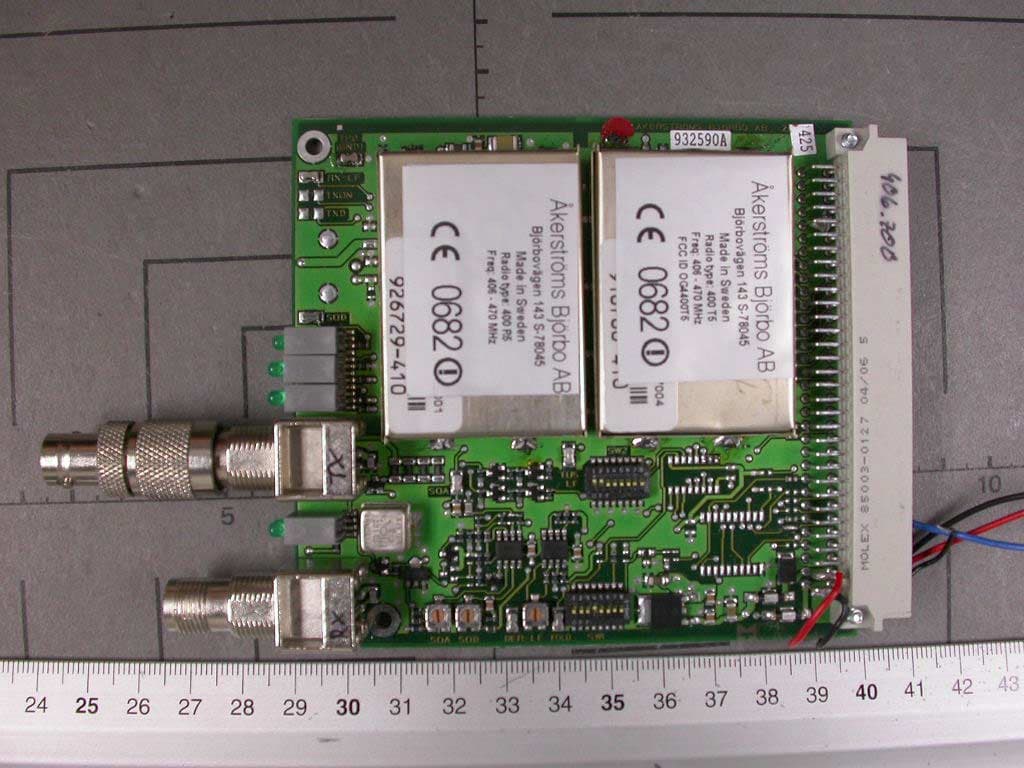
OG4400T5
Apr 26, 2005Remote Control Transmitter Module
Equipment Class
TNB - Licensed Non-Broadcast Station Transmitter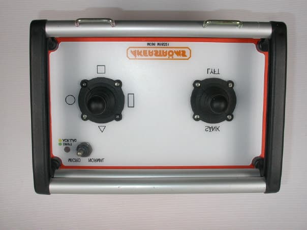
OG4MC96
Jun 22, 2004Remote Control Transmitter
Equipment Class
TNT - Licensed Non-Broadcast Transmitter Worn on Body