OG4S500ST
Akerstroms Bjorbo AB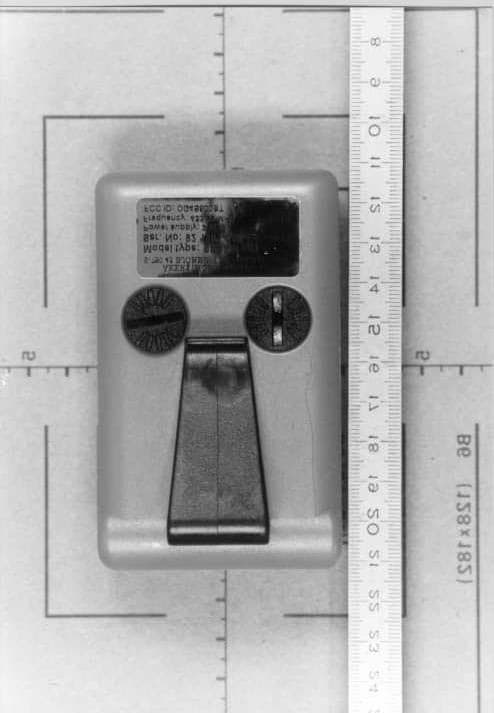
Click to zoom
Application Details
- Equipment Class
- DSC - Part 15 Security/Remote Control Transmitter
- Date of Grant
- Aug 16, 1999
- Application Purpose
- Original Equipment
- Date of Application
- Apr 19, 1999
- Frequency Range
- 433.92000000 - 433.92000000
- Company
- Akerstroms Bjorbo AB
- Country
- Sweden
Documents & Files
Document Text
Text extracted from the exhibit documents filed with the FCC. Open a document above to read the original.
External Photos
FCC-ID: OG4S500ST EMV-PrüfzentrumEMI/EMC-Testcenter Top of unit - Sesam 503 FCC-ID: OG4S500ST EMV-PrüfzentrumEMI/EMC-Testcenter Rear of unit - Sesam 503
ID Label/Location Info
FCC-ID: OG4S500ST EMV-PrüfzentrumEMI/EMC-Testcenter Label or identifying mark - Sesam 503
Internal Photos
FCC-ID: OG4S500ST EMV-PrüfzentrumEMI/EMC-Testcenter Top view - printed board - Sesam 503 FCC-ID: OG4S500ST EMV-PrüfzentrumEMI/EMC-Testcenter Bottom view - printed board - Sesam 503
Operational Description
ÅKERSTRÖMS BJÖRBO AB, S-78045 BJÖRBO, SwedenPhone +46 241 25000Fax +46 241 23290 Fax service dept +46 241 25090Vat No SE556153982501Säte/Registered office BJÖRBO Basic requirements for the owners Warning Do not make changes on the devices. Violation will invalidate interference emission certification (FCC, RSS, CE), and the manufacturer’s warranty. This device complies with Part 15 of the FCC rules. Operation is subject to the following two conditions: (1) this device may not cause harmful interference, and (2) this device must accept any interference received, including interference that may cause undesired operation. Note This equipment has been tested and found to comply with the limits for a Class B digital device, pursant to Part 15 of the FCC Rules. These limits are designed to provide reasonable protection against harmful interference in a residential installation. This equipment generates, uses in accordance with the instructions, may cause harmful interference to radio communications. However, there is no guarantee that interference will not occur in a particular installation. If this equipment does cause harmful interference to radio or television reception, which can be determined by turning the equipment off and on, the user is encouraged to try to correct the interference by one or more of the following measures. • Reorient or relocate the receiving antenna • Increase the separation between the equipment and receiver • Connect the equipment into an outlet on a circuit different from that to which the receiver is connected • Consult the dealer Sesam 500 – Door opening system SESAM 500 has been developed to meet the markets requirements for an attractively priced, easily operated and powerful door opening system. SESAM 500 is flexible and simple in operation, and it is based on modern digital radio technology. The transmitter is available in four versions. SESAM 501 is a small hand-held transmitter with one function. SESAM 503 is technically identical to SESAM 501, but has three functions. SESAM 512 is a hand-held or vehicle-mounted transmitter with facilities for communication with up to twelwe receivers. SESAM 599 has the same facilities as SESAM 512, but can communicate with up to 999 receivers. The SESAM 599 is also provided with a display. The system includes receivers with one or three output relays. Sesam 501 Sesam 503 Sesam 512 Sesam 599 Receiver Receiver Plug-in model TECHNICAL DESCRIPTION SESAM 500 Type of equipment: Transmitters Sesam 501, Sesam 503, Sesam 512, Sesam 599. Receivers Sesam R1 - R5 Characteristics of the equipment Frequency band: ISM-band class 1, 433,92 MHz Type of modulation: ASK, 1K20A1D Output power: 74.0 dBμV/m@ 3m test distance Operating temperature range: -25ºC – +55ºC Sesam 501 Number of functions: 1 Power source: 9V battery Current: 25 mA Size: 100 x 60 x 25 mm Sesam 503 Number of functions: 3 Power source: 9V battery Current: 25 mA Size: 100 x 60 x 25 mm Sesam 512 Number of functions: 3 Number of codes: 12 Power source: 9V battery or external source Current: 25 mA Size: 142 x 68 x 26 mm Sesam 599 Number of functions: 3 Number of codes: 12 Power source: 9V battery or external source Current: 25 mA Size: 142 x 68 x 26 mm Sesam R1 – R5 Number of functions: 1 or 3 Sensitivity: better than –95 dBm Relay load: max 400 VAC, 6 A, 1500 W, resistive load Power source: 230 VAC, or 24 VAC or 12 – 24 VDC Size: 152 x 102 x 42 mm or plug-in model 80 x 72 x 35 mm ÅKERSTRÖMS BJÖRBO AB Tel +46 (0)241 - 25000. Telefax +46 (0)241 - 23290 780 45 Björbo www-service: htt p:// www.akerstroms.se Sweden e-mail: [email protected] We reserve the ri ght to alter t echnical data without notice
Test Report
EMV-Prüfzentrum EMI/EMC-Testcenter Straubing, February 25, 1999 T E S T - R E P O R T No. 56502-90128-1 for Sesam 503 Variant covered by this report: Sesam 501 Remote control transmitter (433.92 MHz) Applicant:Akerströms Björbo AB Purpose of testing:To show compliance with FCC Code of Federal Regulations, Part 15 Subpart C, Section §15.231 Industry Canada Radio Standards Specification RSS-210 Issue 2, Section 6.1 (Category I Equipment) Note: The test data of this report relate only to the individual item which has been tested. This report shall not be reproduced except in full extent without the written approval of the testing laboratory. Page 1 of 51 Pages EMV-Prüfzentrum EMI/EMC-Testcenter Table of Contents 1.Administrative Data ....................................................................................3 2.Summary of Test Results ...........................................................................4 3.Operation Mode of EUT..............................................................................5 4.Configuration of EUT and Peripheral Devices............................................6 5.Measuring Methods ....................................................................................7 5.1. Bandwidth of Emission(FCC §15.231.c / RSS-210 Section 6.1.1.c) ...................................................................................................7 5.2. Radiated Emission 30 MHz - 1 GHz (FCC §15.205.a,b, §15.209, §15.231.b / RSS-210 Sections 6.1.1.b, 6.3)............................8 5.3. Radiated Emission 1 GHz - 5 GHz (FCC §15.205.a,b, §15.209, §15.231.b / RSS-210 Sections 6.1.1.b, 6.3).........................................10 6.Equipment List..........................................................................................12 7.Photographs Taken During Testing..........................................................14 8.List of Measurements ...............................................................................22 8.1. List of Measurements According To FCC Part 15 Subpart C...............23 8.2. List of Measurements According To Industry Canada RSS-210 ..........24 9.Referenced Regulations ...........................................................................25 10. Test Results..............................................................................................26 FCC ID: OG4S500STTest Report No. 56502-90128-1 Page 2 of 51 Pages EMV-Prüfzentrum EMI/EMC-Testcenter 1.Administrative Data Equipment Under Test (EUT): Sesam 503 Serial number:92 1863-000 Type of equipment:Remote control transmitter (433.92 MHz) Parts/accessories:--- FCC-ID:OG4S500ST Applicant:Akerströms Björbo AB (full address)S-780 45 Björbo Sweden Contract identification:--- Contact person:Mr. Bernt Eriksson Manufacturer:Akerströms Björbo AB Receipt of EUT:February 15, 1999 Date of test:February 16 to February 18, 1999 Note: Test Laboratory:Senton GmbH EMI/EMC Test Center (full address):Aeussere Fruehlingstrasse 45 D-94315 Straubing Germany Contact person:Mr. Johann Roidt FCC file number:31040/SIT 1300F2 Industry Canada file number:IC 3050 Responsible for testing:Thomas Eberl Responsible for test report:Thomas Eberl FCC ID: OG4S500STTest Report No. 56502-90128-1 Page 3 of 51 Pages EMV-Prüfzentrum EMI/EMC-Testcenter 2.Summary of Test Results The tested sample complies with the requirements set forth in the Code of Regulations Part 15 Subpart C, Section §15.231 (intentional radiators) of the Federal Communication Commission (FCC) and the Radio Standards Specification RSS-210 Issue 2, Section 6.1 for Low Power Licence-Exempt Radiocommuniction Devices of Industry Canada. Johann RoidtThomas Eberl Technical ManagerTest Engineer FCC ID: OG4S500STTest Report No. 56502-90128-1 Page 4 of 51 Pages EMV-Prüfzentrum EMI/EMC-Testcenter 3.Operation Mode of EUT EUT is transmitting continuously with modulation, supplied by battery (9 V DC) FCC ID: OG4S500STTest Report No. 56502-90128-1 Page 5 of 51 Pages EMV-Prüfzentrum EMI/EMC-Testcenter 4.Configuration of EUT and Peripheral Devices Configuration of EUT EUT is configured as stand-alone device Configuration of cables of EUT Not applicable Configuration of peripheral devices connected to EUT Not applicable FCC ID: OG4S500STTest Report No. 56502-90128-1 Page 6 of 51 Pages EMV-Prüfzentrum EMI/EMC-Testcenter 5.Measuring Methods 5.1. Bandwidth of Emission(FCC §15.231.c / RSS-210 Section 6.1.1.c) The Bandwidth of Emission is measured with a spectrum analyzer connected to measuring antenna (radiated measurement) or test fixture while EUT is operating in transmit mode with modulation at the appropriate center frequency. To increase received signal level distance to EUT is reduced (appropriate level offset is included). The spectrum analyzer was set to: RBW = 10 kHz, VBW = 10 kHz, span = 1 MHz, sweep = 40 ms See figure 1 for the measurement setup. Test equipment used (see equipment list for details): 02, 55, 67 5 2 1 4 3 Figure 1: Measurement setup for bandwidth of emission test 1 Transmitter (EUT) 3 Test fixture 2Wooden table4Test cable 5Spectrum analyzer FCC ID: OG4S500STTest Report No. 56502-90128-1 Page 7 of 51 Pages EMV-Prüfzentrum EMI/EMC-Testcenter 5.2. Radiated Emission 30 MHz - 1 GHz (FCC §15.205.a,b, §15.209, §15.231.b / RSS-210 Sections 6.1.1.b, 6.3) Radiated emissions are measured over the frequency range from 30 MHz to 1 GHz. The bandwidth of the EMI-receiver is set to 120 kHz and the detector- function is set to CISPR quasi-peak. The test setup is made in accordance with ANSI C63.4-1992. Measurements are made in both the horizontal and vertical planes of polarization. Preliminary scans are taken in a semi-anechoic room using a spectrum analyzer with the detector function set to peak. Hand-held or body-worn devices are rotated through three orthogonal axes to determine which attitude and configuration produces the highest emission relative to the limit and therefore shall be used for final testing. All tests are performed at a tes…
Text truncated - open the document above for the full version.
Contact Information
Applicant
Lars-Olov Liss(VD/President)
Technical Contact
Senton GmbHJohann Roidt
[email protected]49-9421-55-22-13
Aeussere Fruehlingstrasse45 · D-9415 Straubing · Germany
Non-Technical Contact
Senton GmbHJohann Roidt
[email protected]49-9421-55-22-13
Test Firm
TUV SUD Product Service GmbH PS-EMC-STRRainer Heller
Technical Specifications
| # | Rule Parts | Frequency Range | Power Output | Tolerance |
|---|---|---|---|---|
| 1 | 15C | 433.92 MHz - 433.92 MHz | - | % |
Other Applications from Akerstroms Bjorbo AB

OG4-TRXBQ900
Dec 16, 2012Radio module TRX BQ900
Equipment Class
DXX - Part 15 Low Power Communication Device Transmitter
OG4-K3
Jun 05, 2012Sesam 800 Radio Remote Control
Equipment Class
DXX - Part 15 Low Power Communication Device Transmitter
OG4-RXDIN
Jun 04, 2012Sesam 800 Remote Radio Control
Equipment Class
DXX - Part 15 Low Power Communication Device Transmitter
OG4400T5
Apr 26, 2005Remote Control Transmitter Module
Equipment Class
TNB - Licensed Non-Broadcast Station Transmitter
OG4MC96
Jun 22, 2004Remote Control Transmitter
Equipment Class
TNT - Licensed Non-Broadcast Transmitter Worn on Body