OGK30011534001
RF Technologies Inc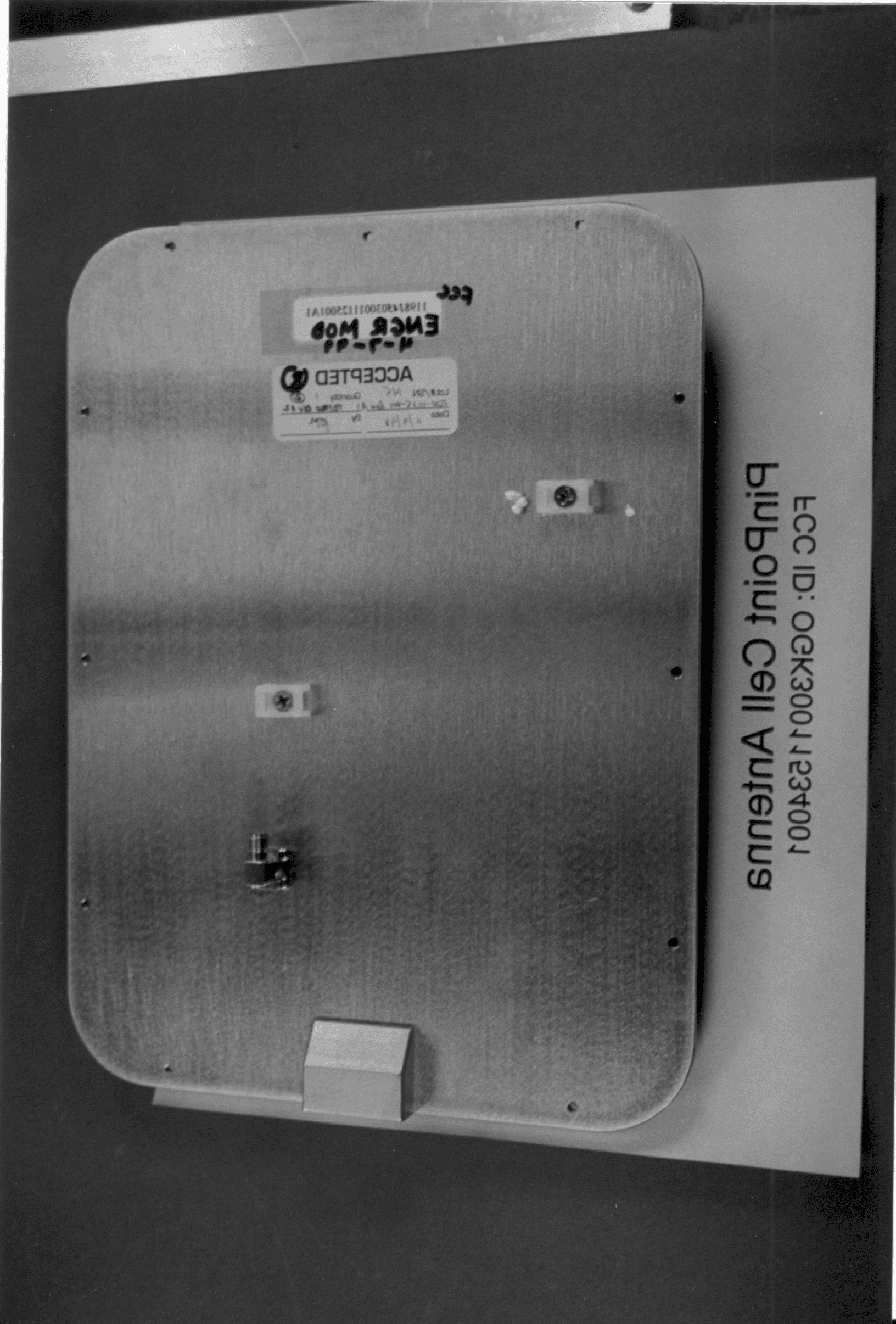
Click to zoom
Application Details
- Equipment Class
- DSS - Part 15 Spread Spectrum Transmitter
- Date of Grant
- Aug 01, 1999
- Application Purpose
- Original Equipment
- Date of Application
- May 09, 1999
- Frequency Range
- 2442.00000000 - 2442.00000000
- Company
- RF Technologies Inc
- Country
- United States
Documents & Files
Document Text
Text extracted from the exhibit documents filed with the FCC. Open a document above to read the original.
Users Manual
PinPoint Corporation System Hardware Introduction FCC REGULATIONS This system complies with Part 15 of the FCC Rules. Operation is subject to the following two conditions: (1) this device may not cause harmful interference, and (2) this device must accept any interference received, including interference that may cause undesired operation. WARNINGS Changes or modifications not expressely approved by PinPoint Corporation could void the userís authority to operate the equipment. Contents Section 1: Introduction to the System WELCOME Welcome to the 3D-iD system. The 3D-iD system is an LPS (Local Positioning System) designed to take asset and personnel tracking to the next level. Where GPS supplies global, outdoor, positioning data, the 3D-iD LPS system provides local, indoor and outdoor, positioning data. In addition, the system comes with a variety of tools that enable you to track and monitor ìtaggedî assets in three- dimensional space. The purpose of this manual is to introduce you to the sys- temís technology and walk you through the an overview of its installation. There are myriad applications for the technology ñ applications which previous technologies, due to their many limitations ñ cannot address. In manufacturig and distribution applications, the 3D-iD system can help shippers find containers in shipping yards. In healthcare, it can be used to insure that hospitals can keep track of their valuable assets, decreasing lost equipment and increasing efficiency. The 3D-iD system relies on a combination of hardware and software. Before examining the systemís operation, weíll take a brief look at the components that make up the system. The two elements relevant to an end-user include: ∑Tags that are attached to assets or people which are to be tracked ∑Asuite of software applications that present the user with information about Tag locations and conditions. The remaining elements, all of which have to be installed and configured, include: ∑The Antennas, ∑The Cell Controllers ∑The software infrastructure. In this manual, weíll briefly explore each of these elements. HOWTHE3D-ID SYSTEMWORKS: The 3D-iD system is comprised of two basic parts, a hardware and a software system. The combination of the two systems allows tags to be located, tracked and secured throughout an installation site. The hardware side of the system generates Tag Antenna Distance (TAD) data, while the software side of the sys- tem converts that data to other forms, and presents it to the end-user. The hardware side of the system consists of three parts: Tags, Antennas and Cell Controllers. ïTags are the objects tracked ñ they can be affixed to an asset or person, allowing the system to track that asset or person. ïAntennas are stationary devices from which TAD distances are meas- ured. They are supplied with DC power via their coaxial cable connection to a Cell Controller. ïCell Controllers are the brains of the hardware side of the system. They coordinate the antennas and use the roundtrip time required for a radio signal to travel from an antenna to a tag to calculate the distance between the Tags and Antennas. This is what we call TAD (Tag-Antenna Distance) data. Once TAD data has been generated, it is forwarded to a ViewPoint Server on the software side of the system. Which then converts that data into Location and Alert data and publishes it to client applications. Location (or LOC) data is data that indicates the Location (which are derived from logical statements involving TAD variables) that a tag is in. ALocation can be a room, a wing or even an entire floor, depending on the configuration of the system. Alert (or ALR) data is data that is generated based on certain ëtriggeríevents for single tags or pairs of tags. There are two basic groups of alert conditions. The first group, alerts associated with a single tag, can be set when a tag enters or exits an area or when a tag remains within a certain location for a set period of time. The second group, alerts associated with a pair of tags, can be triggered when one tag enters an area without the other, when the two tags are near one another or when the two tags are far from one another. Detailed information about the ViewPoint Server is available in the Userís Manual. In brief, ViewPointís NTServices (which are programs that run in the background on the server, and require no user input) receive the TAD data. These services then use lookup tables created by the user when the software system is setup to convert the TAD data into Location (LOC) and Alert (ALR) data. The services then publish that data to various client applications which end-users use to view specific data. The services can also publish data to a Recorder service, which saves data to a database. Combined, the hardware and software elements of the PinPoint system can generate a wide variety of data based on the location of tags. HOWTHEHARDWAREWORKS: The purpose of PinPointís 3D-iDís hardware system is to determine the distance between tags and antennas. There are three elements involved in this process. The first two are the tags and the antennas. The third is the cell controller, which coordinates the actions of the tags and antennas ñ and interprets their signals. Each tag is ëoní(and detectable) for a very short period of time. Because this ìonî time is so brief - relative to the ìoffî times - the chances of two tags being on at once are very remote. With this in mind, we can examine the Cell Controllerís operation. The Cell Controllerís basic job is to record the amount of time a radio signal takes to go between each antenna and the tag which is cur- rently ëoníand back. The Cell Controller can calculate the distance between a single Antenna and a Tag from the transmission time and the speed of light. The following is the procedure it follows for deriving the time needed for a radio signal to travel between the Tag and the Antenna: 1. The Cell Controller sends an antenna a spread spectrum radi…
Text truncated - open the document above for the full version.
Users Manual
PinPointLocal Positioning Systems Cell Controller Installation Manual W arnings 2 Included In This Package 3 About Antennas 4 Placement 5 Mounting 6 Inst alling 7 Technical Specification 7 ' Copyright 1999, PinPoint Corporation. All right s reserved. cc.qxd 5/5/99 4:28 PM Page 1 Warnings Always place the Cell Controller in a well ventilated area. Never block the Cell Controllers air vents. Keep the Cell Controller away from water. Never attach the Antenna cables while the Cell Controller is powered on! Equipment damage may result! Do not overtighten the Coaxial Cables! Do not kink or tightly bend the Coaxial Cables! Changes and modifications not expressely approved by PinPoint Corporation could void the users authority to operate the equipment. Included in this package 1 Cell Controller 1 AC power cord 2 PinPointLocal Positioning Systems Picture of Cell Controller ! cc.qxd 5/5/99 4:28 PM Page 2 Installing Cell Controllers About Cell Controllers The Cell Controller is the primary data collection tool of the 3D-iD sys- tem. The Cell Controller coordinates the Antennasbroad- casts and then analyzes the signals returned by the Tags. To do this, the Cell Controller broadcasts spread spectrum signals at 2.44GHz to the 3D-iD Tags via its attached Antennas. It then measures the total time transpired until the return signals (at 5.77GHz) are received from the Tags. Using this information it calculates the distance the Tag is from the Antenna, called Tag Antenna Distance (TAD) data. The Cell Controller sends the data it generates to the ViewPoint Software via a standard ethernet link. The soft- ware will, using the data collected from several Antennas, accurately determine a Tags location. 3 cc.qxd 5/5/99 4:28 PM Page 3 Cell Controller Placement The Cell Controller must be located sufficiently close to each of its antennas in order to account for a fixed cable length (100 feet). The Cell Controller must be located in proximity to a standard AC power outlet (grounded) and an appropriate network jack. The Cell Controller must be placed in a location with adequate ventilation. 4 PinPointLocal Positioning Systems cc.qxd 5/5/99 4:28 PM Page 4 Installing Cell Controllers Mounting the Cell Controller The Cell Controller may be placed upon any sufficiently sturdy, flat surface such as a table or a desk. Remember to allow for adequate ventilation. Other Cell Controller mounts that may be purchased sepa- rately through your PinPoint sales representative are: - Horizontal Mount - Vertical Mount - Durable Mount (NEMArated for harsh environments) 5 cc.qxd 5/5/99 4:28 PM Page 5 Installing the Cell Controller 1.Attach the enclosed power cord to the AC outlet on the Cell Controller. Plug the power cord into the wall outlet. 2.Attach the appropriate network cable (ethernet) to the Cell Controller. The ethernet cable should be connected to the ViewPoint network. 3.Attach up to 16 Antennas (depending upon the system layout) to the antenna ports using the specified 3D-iD Coaxial Cables (shipped separately). Attach the Antennas where indicated by your certified system inte- grator. -Never attach the Antenna cables while the Cell Controller is powered on! Equipment damage may result! -Do not overtighten the coaxial cables! -Do not kink the coaxial cables! 4.Turn on the Cell Controller using the power switch. The Cell Controller will enter a mode where it continuously searches for the server software on the network. 6 PinPointLocal Positioning Systems Picture of rear of Cell Controller, with cables. cc.qxd 5/5/99 4:28 PM Page 6 Installing Cell Controllers Maintaining the Cell Controller Once operating, the Cell Controller will continue to function with minimal maintenance. Dust Screen There is a permanent dust screen covering the ventilation fan that should be checked every six months. If necessary, the guard and screen should be removed, cleaned and replaced. Be sure to power off the Cell Controller before cleaning the screen. Fuse The Cell Controllers fuse (#313-xA250V fuse) should be replaced as necessary. 7 cc.qxd 5/5/99 4:28 PM Page 7 PinPointLocal Positioning Systems Technical Specifications This device complies with Part 15 of the FCC Rules. Operation is subject to the following two conditions: (1) this device may not cause harmful interference, and (2) this device must accept any interference received, including interference that may cause undesired opera- tion. Frequency: Tx:2.442 GHz Rx:5.770 GHz Radiated Power: <1 W EIRP AC Power: 110/220V AC, 50/60 Hz Read Range: 125 feet Performance:Detect a 3 second tag in a population of: 200 tags within 10s (99% confidence) 500 tags within 25s (99% confidence) Dimensions: 18 x 9 x 6 Environment: -20 C 50 C (operating range) 5% - 95% humidity, no condensation See Cell Controller Data Sheets for details PinPoint Corporation One Oak Park Bedford, MA01730 http://www.pinpointco.com phone/fax: 781-687-9720 - 781-687-9730 cc.qxd 5/5/99 4:28 PM Page 8
Users Manual
A20-EC Antenna Installation Manual © Copyright 1999, PinPoint Corporation. All rights reserved. Warnings......................................2 Included In This Package.............3 About Antennas............................4 Placement.....................................5 Mounting............................................6 Installing ......................................7 Technical Specification ................7 Warnings The 3D-iD Antenna is intended for indoor use only. Use of the Antenna outdoors can cause damage to its internal components. Contact your PinPoint sales representative for details regarding outdoor use of the 3D-iD system. Do not mount the Antenna in places that are excessively humid or where it is likely to get wet. When placing your antenna, keep in mind that metallic objects, dense walls, microwave ovens and other obstacles can alter radio signals, limiting the Antennaís effectiveness. See your certified system integrator for proper Antenna placement. The antenna must be installed so that there is at least a 6 inch gap between it and any possible contact with people. Failure to install it in this fashion may invalidate the userís license to operate this product. Included In This Package 1 Antenna 1 Antenna mount, including: 1 Base plate 1 Mount post 1 Mounting Plate 2 Screws (1/2î) 2 Washers 1 Allen wrench 1 Antenna card (optional) CLOSE-UP OF ANTENNA AND MOUNT (ATTACHED) About Antennas The 3D-iD Antennas are attached to the Cell Controller and are DC powered by special, low-loss Coaxial Cables. Up to sixteen (16) Antennas may be attached to a single Cell Controller. The Cell Con- troller generates a 2.44GHzradio signal which it sends to the Antenna via the Coaxial Cable connecting them. The Antenna broadcasts the signals to the surrounding area with an ellipsoidal radiation pattern. Any Tags that are within range recieve the signal, add their serial number, and transflect the signal back to the antenna at 5.77GHz. The Antenna then sends the response back down to the Cell Controller which measures the delay between when the signal was sent and when it was received, thus generating Tag-Antenna Distance (TAD) data. Diagram of Cell Controller, Tags, Antennas and the Software system. The Antennas come with a mount allowing them to be attached to a flat surface, such as a wall. For other mounting configurations, please contact your certified 3D-iD system integrator. Antenna Placement Tips The exact location of Antennas will be determined by a certified 3D-iD system integrator. The Antennas will be positioned to optimize the locating capability of the system in accordance with the requiremetns set forth by the customer. The Antennas must be placed within sufficient distance of their corre- sponding Cell Controller (100 feet). The Coaxial Cables connecting an Antenna to its Cell Controller must not be stretched, kinked or other- wise damaged during Antenna installation. The Antennas should not be placed very close to metal walls, micro- wave ovens or other objects that will hinder their performance. Metallic objects and dense walls can alter the radiation pattern of the Antennas. The Antennas should be mounted in locations that prevents accidental contact or intentional destruction. Mounting the Antennas near ceilings and out of reach is strongly recommended. The antenna must be installed so that there is at least a 6 inch gap between it and any possible contact with people. Failure to install it in this fashion may invalidate the userís license to operate this product. Mounting the Antenna The Antenna mount is intended for flat walls of varying construction. Please contact your certified 3D-iD system integrator for other mount- ing applications. 1) Using the appropriate hardware, securely attach the circular base- plate of the mount to a flat surface in the desired location. Ensure sufficient clearance is left between the baseplate and any nearby ceilings and walls to allow for full adjustment of the Antenna once it is mounted. 2) Attach the mountís post to the base plate. Tighten the lock nut with a pliers. 3) Prepare the Antenna by attaching the small, rectangular mounting plate to the back of the Antenna with the two (2) included 1/2î screws and washers. 4) Attach Antenna to mount by aligning the mounting plate on the Antenna with the threaded bolt at the end of the post and rotating the Antenna until it stops. Tighten the locknuts to secure the Antenna. PICTURES OF 1) BASE PLATE AND POST IN WALL 2) BACK OF ANTENNA WITH MOUNTING PLATE 1) Loosen both set screws on the mount with the enclosed wrench. Align the Antenna so it is oriented in the direction indicated by the system integrator. Tighten both set screws Technical Specification 2) Attach the Antenna to its appropriate Coaxial Cable. For tension relief, insert a tie wrap through theguide on the back of the antenna and secure the Coaxial Cable with the tie-wrap. Installing the Antenna PICTURE OF MOUNTED ANTENNA Frequency:Tx: 2442 + 83.5 MHz Rx: 5800 + 150 MHz Power:12 V DC (supplied from coaxial cable) Radiation Pattern:Ellipto-conical (62° azimuth, 32° elevation) Dimensions:10î x 7îx 2î Environment: -20°C ñ 40°C (operating range) 5% - 95% humidity, no condensation See Cell Controller/Antenna Data Sheets for details PinPoint Corporation One Oak Park Bedford, MA 01730 http://www.pinpointco.com phone: 781-687-9720 fax: 781-687-9730
Cover Letter(s)
Curtis-Straus LLC 527 Great Road Littleton, Massachusetts 01460 Tel: (978) 486-8880 Fax: (978) 486-8828 Web: http://www.curtis-straus.com e-mail: [email protected] May 10, 1999 Federal Communications Commission Re: FCC Part 15 Certification for PinPoint Corporation (FCC ID: OGK30011534001) Dear Sir: We are submitting an application for PinPoint Corporation's 3D-iD Cell Controller Asset Tracking System (model number: ACC-CC16-01) via the EAS electronic filing system. Please note that we are simultaneously requesting the following services: Certification$940.00 Request for Confidentiality$135.00 PinPoint is requesting that the Block Diagram, Schematics and Bill of Materials (exhibits 6.1, 6.2 and 6.3) be kept confidential in the FCC application because of the proprietary design developed by PinPoint that is unique to the industry. Please feel free to contact me with any questions. Best regards, Paul Hare EMC Manager CC w/enclosures Hewlett-Packard Jaime Ash
Cover Letter(s)
Curtis-Straus LLC 527 Great Road Littleton, Massachusetts 01460 Tel: (978) 486-8880 Fax: (978) 486-8828 Web: http://www.curtis-straus.com e-mail: [email protected] CONFIDENTIAL May 10, 1999 Federal Communications Commission Re: Confidentiality for PinPoint Corporation (FCC ID: OGK30011534001) Due to the proprietary design developed by PinPoint that is unique to the industry, PinPoint is requesting confidentiality for the following exhibits of Curtis-Straus report number 990390 (FCC ID: OGK30011534001): 6.1: Block Diagram 6.2: Schematics 6.3: Bill of Materials Please feel free to contact me with any questions. Best regards, Paul Hare EMC Manager
External Photos
FCC Application for PinPoint – External Photos • •• • FCC ID: OGK30011534001 • •• • Report No. 990390 26-Jun-01 Page 1 of 3 ______________________________________________________________________ 4.0Equipment Photographs External Photos FCC Application for PinPoint – External Photos • •• • FCC ID: OGK30011534001 • •• • Report No. 990390 26-Jun-01 Page 2 of 3 ______________________________________________________________________ FCC Application for PinPoint – External Photos • •• • FCC ID: OGK30011534001 • •• • Report No. 990390 26-Jun-01 Page 3 of 3 ______________________________________________________________________
ID Label/Location Info
FCC Application for PinPoint – Label Info • •• • FCC ID: OGK30011534001 • •• • Report No. 990390 26-Jun-01 Page 1 of 2 ______________________________________________________________________ 5.0Product Labeling 5.1Label Artwork The label shown in the drawing below will be permanently affixed to the system at the location shown in Exhibit 5.2. FCC Application for PinPoint – Label Info • •• • FCC ID: OGK30011534001 • •• • Report No. 990390 26-Jun-01 Page 2 of 2 ______________________________________________________________________ 5.2 Label Location
Internal Photos
FCC Application for PinPoint – Internal Photos • •• • FCC ID: OGK30011534001 • •• • Report No. 990390 26-Jun-01 Page 1 of 3 ______________________________________________________________________ 4.0Equipment Photographs Internal Photos FCC Application for PinPoint – Internal Photos • •• • FCC ID: OGK30011534001 • •• • Report No. 990390 26-Jun-01 Page 2 of 3 ______________________________________________________________________ FCC Application for PinPoint – Internal Photos • •• • FCC ID: OGK30011534001 • •• • Report No. 990390 26-Jun-01 Page 3 of 3 ______________________________________________________________________
Test Report
MEASUREMENT/TECHNICAL REPORT Company - Model: PinPoint ACC-CC16-01 and ACC-ANT01-01 FCC ID: OGK30011534001 May 10, 1999 Description: This is a report to support a request for an original grant of equipment authorization. Equipment Type: Spread Spectrum Transmitter (DSS) Report prepared for:PinPoint Corporation One Oak Park Bedford, MA 01730 Phone: (781) 687-9720 Fax:(781) 687-9730 Report prepared by:Michael Buchholz Curtis-Straus LLC 527 Great Road Littleton, MA 01460 USA Phone: 978-486-8880 FAX:978-486-8828 FCC Application for PinPoint FCC ID: OGK30011534001 Report No. 990390 15-May-20 ______________________________________________________________________ _____________________________________________________________ Curtis-Straus LLC 527 Great Road Littleton, MA TEL (978) 486-8880 FAX (978) 486-8828 page 2 of 45 Table of Contents LETTER OF AGENCY ...............................................................................................................................................3 INTRODUCTION ........................................................................................................................................................4 EXHIBIT 1: ...................................................................................................................................................................5 1.0 STATEMENT OF CONFORMITY ............................................................................................................................5 EXHIBIT 2 ....................................................................................................................................................................6 2.0 GENERAL DESCRIPTION .................................................................................................................................6 2.1 Product Description ......................................................................................................................................6 2.2 Related Submittal(s) Grants ..........................................................................................................................6 2.3 Test Methodology ..........................................................................................................................................6 2.4 Test Facility...................................................................................................................................................7 2.5 Test Equipment Used.....................................................................................................................................7 EXHIBIT 3 ....................................................................................................................................................................8 3.0 MEASUREMENT RESULTS ...................................................................................................................................8 3.1 Operating Frequency ....................................................................................................................................8 3.2 Maximum Peak Output Power Measurement................................................................................................8 3.3 Electric Field Strength Radiation Measurements .........................................................................................9 3.4 Occupied Bandwidth Measurements ...........................................................................................................30 3.5 Processing Gain Measurement ...................................................................................................................32 3.6 Power Spectral Density Measurement ........................................................................................................36 3.7 Radiofrequency Radiation Exposure Evaluation ........................................................................................37 3.8 Test Setup Photographs...............................................................................................................................38 EXHIBIT 4 ..................................................................................................................................................................39 4.0 EQUIPMENT PHOTOGRAPHS..............................................................................................................................39 EXHIBIT 5 ..................................................................................................................................................................40 5.0 PRODUCT LABELING.........................................................................................................................................40 EXHIBIT 6 ..................................................................................................................................................................41 6.0 TECHNICAL SPECIFICATIONS ............................................................................................................................41 6.1 Technical Description and Block Diagram.................................................................................................41 6.2 Schematics ...................................................................................................................................................42 6.3 Bill of Materials ..........................................................................................................................................43 EXHIBIT 7 ..................................................................................................................................................................44 7.0 INSTRUCTION MANUALS ..................................................................................................................................44 7.1 System Hardware Introduction ..............…
Text truncated - open the document above for the full version.
Test Report
MEASUREMENT/TECHNICAL REPORT Company - Model: PinPoint ACC-CC16-01 and ACC-ANT01-01 FCC ID: OGK30011534001 May 10, 1999 Description: This is a report to support a request for an original grant of equipment authorization. Equipment Type: Spread Spectrum Transmitter (DSS) Report prepared for:PinPoint Corporation One Oak Park Bedford, MA 01730 Phone:(781) 687-9720 Fax:(781) 687-9730 Report prepared by:Michael Buchholz Curtis-Straus LLC 527 Great Road Littleton, MA 01460 USA Phone:978-486-8880 FAX:978-486-8828 FCC Application for PinPoint ••FCC ID: OGK30011534001 •• Report No. 990390 12-May-99 ______________________________________________________________________ _____________________________________________________________ Curtis-Straus LLC •• 527 Great Road •• Littleton, MA •• TEL (978) 486-8880 •• FAX (978) 486-8828 page 2 of 45 Table of Contents LETTER OF AGENCY..............................................................................................................................................3 INTRODUCTION......................................................................................................................................................4 EXHIBIT 1:.................................................................................................................................................................5 1.0STATEMENT OF CONFORMITY...........................................................................................................................5 EXHIBIT 2..................................................................................................................................................................6 2.0 GENERAL DESCRIPTION................................................................................................................................6 2.1Product Description....................................................................................................................................6 2.2Related Submittal(s) Grants........................................................................................................................6 2.3Test Methodology........................................................................................................................................6 2.4Test Facility.................................................................................................................................................7 2.5Test Equipment Used...................................................................................................................................7 EXHIBIT 3..................................................................................................................................................................8 3.0MEASUREMENT RESULTS.................................................................................................................................8 3.1Operating Frequency..................................................................................................................................8 3.2Maximum Peak Output Power Measurement..............................................................................................8 3.3Electric Field Strength Radiation Measurements.......................................................................................9 3.4Occupied Bandwidth Measurements.........................................................................................................30 3.5Processing Gain Measurement.................................................................................................................32 3.6Power Spectral Density Measurement......................................................................................................36 3.7Radiofrequency Radiation Exposure Evaluation......................................................................................37 3.8Test Setup Photographs.............................................................................................................................38 EXHIBIT 4.................................................................................................................…
Text truncated - open the document above for the full version.
Contact Information
Applicant
Michael J. Leigh(QA Manager)
Technical Contact
Curtis-StrausPaul Hare
[email protected]978.486.8880
527 Great Road · Littleton, Massachusetts · United States
Non-Technical Contact
Curtis-StrausPaul Hare
[email protected]978.486.8880
Test Firm
Curtis-Straus LLCJim Lewis
508-486-8880
Technical Specifications
| # | Rule Parts | Frequency Range | Power Output | Tolerance |
|---|---|---|---|---|
| 1 | 15C | 2.44 GHz - 2.44 GHz | 50.00 mW | ppm |
Other Applications from RF Technologies Inc

OGK30013500001
Apr 13, 2004RF Tag
Equipment Class
DXX - Part 15 Low Power Communication Device Transmitter
OGK30011882001
Feb 20, 2001RF Tag model T40
Equipment Class
DXX - Part 15 Low Power Communication Device Transmitter
OGK30011662001
Apr 03, 20003D-iD Asset Locating Tag
Equipment Class
DXX - Part 15 Low Power Communication Device Transmitter