OH27018The Paradigm Translator allows RF intercommunication between Medtronic Minimed Paradigm series insulin pumps and commercially available smartphones running Medtronic application software.
Medtronic MiniMed, Inc.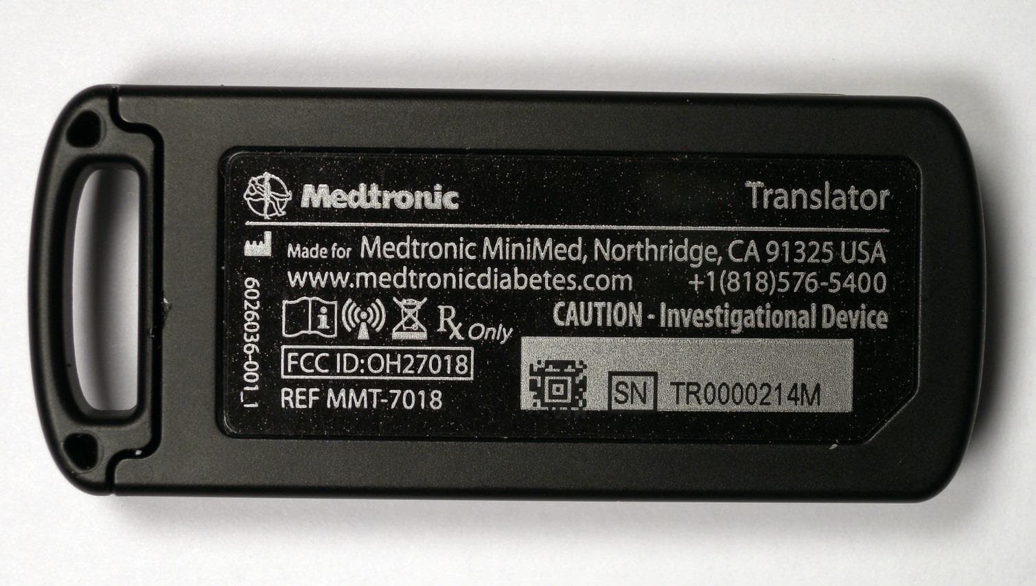
Click to zoom
Application Details
- Equipment Class
- DXT - Part 15 Low Power Transceiver, Rx Verified
- Date of Grant
- Jul 09, 2015
- Application Purpose
- Original Equipment
- Date of Application
- Jul 06, 2015
- Equipment Note
- The Paradigm Translator allows RF intercommunication between Medtronic Minimed Paradigm series insulin pumps and commercially available smartphones running Medtronic application software.
- Frequency Range
- 916.54000000 - 916.54000000
- Company
- Medtronic MiniMed, Inc.
- Country
- United States
Documents & Files
Document Text
Text extracted from the exhibit documents filed with the FCC. Open a document above to read the original.
Users Manual
MiniMed ® Connect User Guide Introduction Thank you for choosing Medtronic Diabetes (legally known as Medtronic MiniMed, Inc.) as your diabetes management partner. MiniMed ® Connect is an accessory of a MiniMed ® 530G or a MiniMed ® Paradigm ® REAL-Time Revel™ sensor-augmented pump system. It is used to provide a passive, secondary display of sensor-augmented pump information on your mobile device. This user guide is designed to help you understand the setup and operation of MiniMed Connect. For details on using the other system components, please see the corresponding device user guides. System components MinMed® Connect Uploader MinMed® Connect App USB ChargerUSB Cable The MiniMed Connect System includes the following components: -1- English • MiniMed Connect Uploader (MMT-7018)—a device that sends data from your pump to your mobile device, enabling your mobile device to display pump and sensor information. To achieve continuous data transmission, the uploader needs to be within six feet of the pump. • MiniMed Connect App (MMT-7001)—an app downloaded to your compatible mobile device. It displays some insulin and continuous glucose monitoring data provided by the pump, as well as system status information. Note:The app can be downloaded on a consumer-owned mobile device with a compatible operating system. A list of compatible operating systems is available in the app store found on your mobile device. • USB charger (MMT-7019)—a device that charges the uploader. It uses a separate, detachable micro-USB cable. Note:Use only the Medtronic USB charger and cable with your uploader. User safety This section includes important safety information such as indications, contraindications, safety warnings, potential adverse reactions. This section also explains how to protect the system from radiation exposure damage. Indications MiniMed Connect is intended to provide a secondary display of CGM and insulin pump information on a suitable consumer electronic device to care partners and users of a MiniMed 530G system or Paradigm REAL-Time Revel system for the purposes of passive monitoring. MiniMed Connect is not intended to replace the primary display of continuous glucose monitoring and insulin pump information on the primary display device. All therapy decisions should be based on blood glucose measurements obtained from a blood glucose meter. MiniMed Connect is not intended to receive information directly from the sensor or transmitter of the sensor-augmented pump system. Contraindications This device is not intended for making treatment decisions. This device is not intended for calculating insulin or other drug doses. This device is not intended for controlling insulin pumps or other drug delivery systems. Dosing decisions should not be made based on this device. The user should follow instructions on the sensor-augmented pump system. This device is not intended to replace self-monitoring practices advised by the healthcare professional. -2- Warnings Warning: Any changes or modifications to the devices not expressly approved by Medtronic Diabetes could interfere with your ability to operate the equipment, cause injury, and void your warranty. Uploader This product contains small parts and may pose a choking hazard for young children. Precautions MiniMed Connect App The MiniMed Connect app cannot tell you about all potential problems. The app does not provide alarms or notify the user; it is intended only to display information. Refer to your pump system user guide for additional precautions. Proper operation of the app relies upon an operating consumer electronic device with proper settings. A non-functioning mobile device, or improper setting changes on the mobile device, may prevent the app from functioning properly. Uploader Do not allow water, or any other liquid, to come in contact with the uploader. The uploader is not waterproof. Always keep the uploader within 6 feet (1.8 meters) of the pump. Warning: Using or storing the uploader outside the specified ranges of its operating conditions or storage conditions may damage the uploader. Notice Radio frequency (RF) communication This device complies with the United States Federal Communications Commission (FCC) and international standards for electromagnetic compatibility. The following information is provided in accordance with Federal Communications Commission (FCC) regulations. This device complies with Part 15 of the FCC Rules. Operation is subject to the following two conditions: (1) This device may not cause harmful interference, and (2) this device must accept any interference received, including interference that may cause undesirable operation. -3- English This device does not interfere with any radio frequency signals transmitted from outside sources. These FCC standards are designed to provide reasonable protection against excessive radio frequency interference and prevent undesirable operation of the device from unwanted electromagnetic interference. Radio frequency (RF) interference from other wireless devices Common consumer electronic devices that transmit in the same frequency band used by the uploader (MMT-7018) may prevent the uploader from receiving the data sent by Medtronic Diabetes therapy management devices. This equipment has been tested and found to comply with the limits for a Class B digital device, pursuant to part 15 of the FCC Rules. These limits are designed to provide reasonable protection against harmful interference in a residential installation. This equipment generates, uses and can radiate radio frequency energy and, if not installed and used in accordance with the instructions, may cause harmful interference to radio communications. However, there is no guarantee that interference will not occur in a particular installation. If this equipment does cause harmful interference to radio or television reception, which can be determined by turning the equipment off and on, the user is encouraged to try to corre…
Text truncated - open the document above for the full version.
Cover Letter(s)
7/7/2015 Federal Communications Commission 7435 Oakland Mills Road Columbia, MD 21046 Subject: Request for Permanent Confidentiality To whom it may concern: In accordance with 47CFR Section 0.457 and Section 0.459 pertaining to confidential material, we hereby request to hold permanently confidential all information contained within the below identified exhibits/document categories submitted pursuant to radio equipment certification requirements for FCC ID: OH2-7018 1. Block Diagram 2. Operational Description 3. Schematics 4. Parts List / Tune-Up Procedure The above material contains trade secrets and proprietary information as specified by 47CFR 0.457(d) and technical data, which would customarily be guarded from competitors. The public disclosure of this information might be harmful to our company and provide unjustified benefits to our competitors. Sincerely, Bob Vitti Bob Vitti Sr Manager, Design Assurance/ Reliability Engineering Medtronic MiniMed
External Photos
Medtronic Paradigm Translator MMT-7018 1. Internal Photos 2. External Photos 1. Internal Photos Medtronic Paradigm Translator PCBA opened: Top View Medtronic Paradigm Translator PCBA opened: Bottom View 2. External Photos Medtronic Paradigm Translator External : Top Medtronic Paradigm Translator External: Bottom Medtronic Paradigm Translator External: Front Medtronic Paradigm Translator External: Right Medtronic Paradigm Translator External: Left Medtronic Paradigm Translator External: Back
ID Label/Location Info
Medtronic Paradigm Translator MMT-7018 1. Internal Photos 2. External Photos 1. Internal Photos Medtronic Paradigm Translator PCBA opened: Top View Medtronic Paradigm Translator PCBA opened: Bottom View 2. External Photos Medtronic Paradigm Translator External : Top Medtronic Paradigm Translator External: Bottom Medtronic Paradigm Translator External: Front Medtronic Paradigm Translator External: Right Medtronic Paradigm Translator External: Left Medtronic Paradigm Translator External: Back
ID Label/Location Info
XX XX-XX C=0-1.0 T3 C=0-1.0 T3 VERSION STATUS DRAWN APPVD VALID DATE VER DESCRIPTION ECO 2SEE ECO DAP 1.815 .734 5X R.044 45° .584 4 57 7 "MC123456M" DENOTES SAMPLE SERIAL NUMBER. LETTERS WILL REMAIN "MC______M" WHILE SERIAL NUMBER IS VARIABLE. 6 ALL TEXT AND IMAGES SHALL BE A MINIMUM OF 0.0625" AWAY FROM THE EDGE AND CONTAINED IN THE OVERALL DIMENSIONS 5 REFERENCE AREA FOR PANTONE 877 GRAY BACKGROUND BEHIND 2D BARCODE AND SERIAL NUMBER 4 AREA LEFT FOR 2D DATA MATRIX ECC200 BARCODE. MUST BE AT LEAST 4mm X 4mm 3 DRAWING SHOWN FOR EXAMPLE ONLY. FOR SPECIFIC ARTWORK, SEE MP PART NUMBER IN TABLE 1 2. MATERIAL: .007" THK. 005 - l11105 CLEAR POLYESTER REAR ADHESIVE: 467MP 1 VENDOR: USE PART NUMBER AND PART REVISION SHOWN IN TABLE 1 TO CERTIFY PARTS. VERSION SHOWN IN TITLE BLOCK FOR MEDTRONIC MINIMED REFERENCE ONLY. NOTES: UNLESS OTHERWISE SPECIFIED. QUALITY REQUIREMENTS NOTE: THE FOLLOWING FOR MEDTRONIC MINIMED RECEIVING INSPECTION USE. FOR SUPPLIER REFERENCE ONLY. 1.0 REFERENCE DOCUMENTS 1.1 DIM1002 1.2 DIM1540 2.0 VISUAL INSPECTION 2.1 INSPECT EXTERNAL SURFACES FOR CRACKS, SCRATCHES AND DEFECTS 3.0 MECHANICAL INSPECTION 3.1 SAMPLING C=0-1.0 3.2 EQUIPMENT T3 4.0 CERTIFICATE OF COMPLIANCE REQUIRED. -001 6 TABLE 1 1 3 PART NO. PART VER. ARTWORK NO. ARTWORK VER E.C.O. NO. 6026036-001 2 MP6026036-0012 A D9195658-012 12/01 B C D 4 3 2 1 4 3 2 1 C A B D SOLIDWORKS OF THE PART DISCLOSED HEREIN OR FOR ANY OTHER PURPOSE WITHOUT THE PRIOR WRITTEN PERMISSION OF MEDTRONIC MINIMED. AND OTHER INFORMATION CONTAINED THEREIN, MAY NOT, IN WHOLE OR IN PART, BE DUPLICATED OR DISCLOSED OR USED FOR THE MANUFACTURE THIS DRAWING CONTAINS DESIGNS AND OTHER INFORMATION WHICH ARE THE PROPERTY OF MEDTRONIC MINIMED. THIS DRAWING, AND THE DESIGNS 1 Z00 ALL DIM ARE IN INCHES 2:1 1 6026036 2 1 1/32 TYPE APPVD B VER DWG NO DO NOT SCALE DRAWING OF SHEET SCALE MAX MAX FILLET RADII BREAK ALL EDGES PER ANSI B46.1 SURFACE FINISH ± FRACTIONS ANGLES DECIMAL .XX ± .XXX ± .XXXX ± .01 .005 .0005 ± 1° TOLERANCES UNLESS OTHERWISE SPECIFIED ALL DIM APPLY AFTER FINISH D. PAVELL 9/24/14 DRAWN DATE DATE CHECKED APPVD DATE DATE DATE APPVD TITLE SIZE LABEL, BOTTOM, TRANSLATOR PARADIGM
Internal Photos
Medtronic Paradigm Translator MMT-7018 1. Internal Photos 2. External Photos 1. Internal Photos Medtronic Paradigm Translator PCBA opened: Top View Medtronic Paradigm Translator PCBA opened: Bottom View 2. External Photos Medtronic Paradigm Translator External : Top Medtronic Paradigm Translator External: Bottom Medtronic Paradigm Translator External: Front Medtronic Paradigm Translator External: Right Medtronic Paradigm Translator External: Left Medtronic Paradigm Translator External: Back
RF Exposure Info
RADIO FREQUENCY EXPOSURE REPORT FOR THE Device: Translator Model: MMT-7018 Report No.: 96784-20 Date of issue: June 25, 2015 PREPARED FOR: Medtronic MiniMed 18000 Devonshire Street Northridge CA 91325-1219 PREPARED BY: Michael Atkinson CKC Laboratories, Inc. 5046 Sierra Pines Drive Mariposa, CA 95338 The test data contained in this report documents the observed testing parameters pertaining to and are relevant for only the sample equipment tested in the agreed upon operational mode(s) and configuration(s) as identified herein. Compliance assessment remains the client’s responsibility. This report may not be used to claim product endorsement by A2LA or any government agencies. This test report has been authorized for release under quality control from CKC Laboratories, Inc. Steve Behm Director of Quality Assurance & Engineering Services CKC Laboratories, Inc. Page 2 of 10 Report No: 96784-20 Purpose: To demonstrate compliance with United States, Canada and/or European Union RF Exposure requirements for Portable equipment (devices used ≤20cm from the body) or Mobile equipment (devices used >20cm from the body) with power output below exemption levels and Mobile equipment, where Maximum Permissible Exposure (MPE) Calculations apply. Device and Antenna Operating Configuration: Device operating at maximum output power with continuous transmission of modulated data. Test Procedure: This equipment is evaluated in accordance with the guidelines set forth in OET Guide 65 & ANSI C95.1 for the US, Health Canada Safety Code 6 & RSS 102 for Canada and EN 62479 or EN 62311 for EU. Other Considerations: Report considers stand-alone configurations only. Simultaneous transmissions are not evaluated. RF Exposure limits are calculated at the mid-point of the operating band. Referenced Test Reports: The following test reports were referenced in conjunction with this assessment: 96784-9 96784-12 96784-13 96784-14 Page 3 of 10 Report No: 96784-20 RF Exposure Assessment Applicability: Limit Used ☒ General Population / Uncontrolled Exposure ☐ Occupational / Controlled Exposure Equipment operational details: Config # Operating Frequency (MHz) Measured Output Power Antenna Gain (dBi) Antenna Type / Configuration EIRP 1 916.5MHz -3.68dBm (0.429mW) 0.85 Integral antenna. (Pulse Engineering W3012) -2.83dBm (0.521mW) 2 2.402-2.480GHz -5.53dBm (0.280mW) 1.7 Integral antenna (Pulse Engineering W3008) -3.83 (0.414mW) * Aggregate Power (#1 + #2) 0.709mW NA NA 0.935mW Exemption Calculation: Config # Distance (mm) US (1.1310) Canada (RSS-102) EU (ICNIRP) Limit (mW) Limit (mW) Limit(mW) 1 ≤5 15.7 7 NA 2 ≤5 9.7 4 NA * ≤5 9.7 4 NA * Note: The combined aggregate power is under the lower limit that applies from the two transmitting frequencies. Page 4 of 10 Report No: 96784-20 Summary: Exemptions: In the case the equipment meets compliance requirements by exemption the product is approved for stand-alone use under mobile or portable conditions without further evaluation. Exemption requires any additional collocation or simultaneous transmission requirements (including necessary separation distances) have been met according to the intended use of the equipment. MPE Calculation Results: In the case the equipment meets compliance by MPE Calculations the product is approved for use under mobile conditions without further testing under the condition that any additional collocation or simultaneous transmission requirements (including necessary separation distances) have been met. It is assumed that the manufacturer shall design the equipment such that the minimum separation distance of 20cm (or greater, as listed above) is met or that the manufacturer provides a protection guide (or installation instructions) to the end user such that the antenna(s) may be installed in accordance with the manufacturer’s instructions in such a manor to maintain the minimum separation distance. General Comments: The Absorption and distribution of Electromagnetic energy in the body is a very complex phenomena that depends on the mass, shape and physiological condition of the body; the orientation of the body with respect to the fields; and, the electrical properties of the body and the environment. Variables that may play a substantial role in possible biological effects are those that characterize the environment (including but not limited to: ambient temperature, air velocity, relative humidity and body insulation); and those that characterize the individual (including but not limited to: age, gender, activity level and existing debilitation or disease). Because innumerable factors may interact to determine specific biological effects of exposure to electromagnetic fields, any protection guide should consider both intended and unintended operational environments and provide guidance for installation and use of the product such that proper separation distances can be maintained. (ANSI C95.1) Page 5 of 10 Report No: 96784-20 RF Exposure Limits United States Compliance Requirements (1.1310): RF Exposure Evaluation Limits Occupational / Controlled Exposure Frequency Range (MHz) Electric Field Strength (V/m) Magnetic Field Strength (A/m) Power Density (mW/cm 2 ) Averaging Time (minutes) 0.3-3.0 614 1.63 *(100) 6 3.0-30 1842/f 4.89/f *(900/f 2 ) 6 30-300 61.4 0.163 1 6 300-1500 --- --- f/300 6 1500-100,000 --- --- 5.0 6 RF Exposure Evaluation Limits General Population / Uncontrolled Exposure Frequency Range (MHz) Electric Field Strength (V/m) Magnetic Field Strength (A/m) Power Density (mW/cm 2 ) Averaging Time (minutes) 0.3-1.34 614 1.63 *(100) 30 1.34-30 824/f 2.19/f *(180/f 2 ) 30 30-300 27.5 0.073 0.2 30 300-1500 --- --- f/1500 30 1500-100,000 --- --- 1.0 30 * Plane wave equivalent power density Limit is calculated based on the mid-band frequency used in the operating frequency range. Stand-Alone Evaluation Exemption Levels: In accordance with KDB 447498 D01 v05r02 Max Output Power at Exemption Limit (mW) Frequency (MHz) d ≤ 50mm 50mm < d ≤ 20cm <100 1 …
Text truncated - open the document above for the full version.
Test Report
This report contains a total of 40 pages and may be reproduced in full only. Partial reproduction may only be done with the written consent of CKC Laboratories, Inc. Medtronic MiniMed TEST REPORT FOR Translator Model: MMT-7018 Tested To The Following Standards: FCC Part 15 Subpart C Section(s) 15.207 & 15.249 Report No.: 96784-12 Date of issue: March 27, 2015 This test report bears the accreditation symbol indicating that the testing performed herein meets the test and reporting requirements of ISO/IEC 17025 under the applicable scope of EMC testing for CKC Laboratories, Inc. We strive to create long-term, trust based relationships by providing sound, adaptive, customer first testing services. We embrace each of our customers’ unique EMC challenges, not as an interruption to set processes, but rather as the reason we are in business. Page 2 of 40 Report No.: 96784-12 TABLE OF CONTENTS Administrative Information .......................................................................................................................... 3 Test Report Information ............................................................................................................................................ 3 Report Authorization ................................................................................................................................................. 3 Test Facility Information ............................................................................................................................................ 4 Software Versions ...................................................................................................................................................... 4 Site Registration & Accreditation Information .......................................................................................................... 4 Summary of Results ................................................................................................................................................... 5 Modifications During Testing ..................................................................................................................................... 5 Conditions During Testing.......................................................................................................................................... 5 Equipment Under Test ............................................................................................................................................... 6 Peripheral Devices ..................................................................................................................................................... 6 FCC Part 15 Subpart C ................................................................................................................................... 7 15.207 AC Conducted Emissions ................................................................................................................................ 7 15.215(c) Occupied Bandwidth ............................................................................................................................... 15 15.249(a) Maximum Output Power ......................................................................................................................... 19 15.249(d) Field Strength of Spurious Emissions and Band Edge ............................................................................. 24 Supplemental Information .......................................................................................................................... 39 Measurement Uncertainty ...................................................................................................................................... 39 Emissions Test Details .............................................................................................................................................. 39 Page 3 of 40 Report No.: 96784-12 ADMINISTRATIVE INFORMATION Test Report Information REPORT PREPARED FOR: REPORT PREPARED BY: Medtronic MiniMed 18000 Devonshire Street Northridge, CA 91325-1219 Morgan Tramontin CKC Laboratories, Inc. 5046 Sierra Pines Drive Mariposa, CA 95338 Representative: Bob Vitti Project Number: 96784 Customer Reference Number: 4500102211 DATE OF EQUIPMENT RECEIPT: March 2, 2015 DATE(S) OF TESTING: March 2 - 4, 2015 Report Authorization The test data contained in this report documents the observed testing parameters pertaining to and are relevant for only the sample equipment tested in the agreed upon operational mode(s) and configuration(s) as identified herein. Compliance assessment remains the client’s responsibility. This report may not be used to claim product endorsement by A2LA or any government agencies. This test report has been authorized for release under quality control from CKC Laboratories, Inc. Steve Behm Director of Quality Assurance & Engineering Services CKC Laboratories, Inc. Page 4 of 40 Report No.: 96784-12 Test Facility Information Our laboratories are configured to effectively test a wide variety of product types. CKC utilizes first class test equipment, anechoic chambers, data acquisition and information services to create accurate, repeatable and affordable test results. TEST LOCATION(S): CKC Laboratories, Inc. 22116 23rd Drive S.E., Suite A Bothell, WA 98021-4413 Software Versions CKC Laboratories Proprietary Software Version EMITest Emissions 5.00.14 Immunity 5.00.07 Site Registration & Accreditation Information Location CB # TAIWAN CANADA FCC JAPAN Bothell US0081 SL2-IN-E-1145R 3082C-1 318736 A-0148 Page 5 of 40 Report No.: 96784-12 SUMMARY OF RESULTS Standard / Specification: FCC Part 15 Subpart C Test Procedure Description Modifications* Results 15.207 Conducted Emissions NA Pass 15.215(c) Bandwidth NA Pass 15.249(a) Maximum Output Power NA Pass 15.249(d) Field Strength of Spurious Emissions and Band Edge NA Pass NA = Not Applicable Modif…
Text truncated - open the document above for the full version.
Contact Information
Applicant
Jonathan Tabalujan(Sr. Electrical Engineer)
Technical Contact
Medtronic MiniMed Inc.Robert G Vitti
[email protected]818-576-4069
18000 Devonshire Street · Northridge · United States
Test Firm
CKC Laboratories, Inc.Steve Behm
Technical Specifications
| # | Rule Parts | Frequency Range | Power Output |
|---|---|---|---|
| 1 | 15C | 916.54 MHz - 916.54 MHz | - |
Other Applications from Medtronic MiniMed, Inc.
OH2BLEGST2
Jul 08, 2024Disposable glucose sensor transmitter
Equipment Class
DTS - Digital Transmission System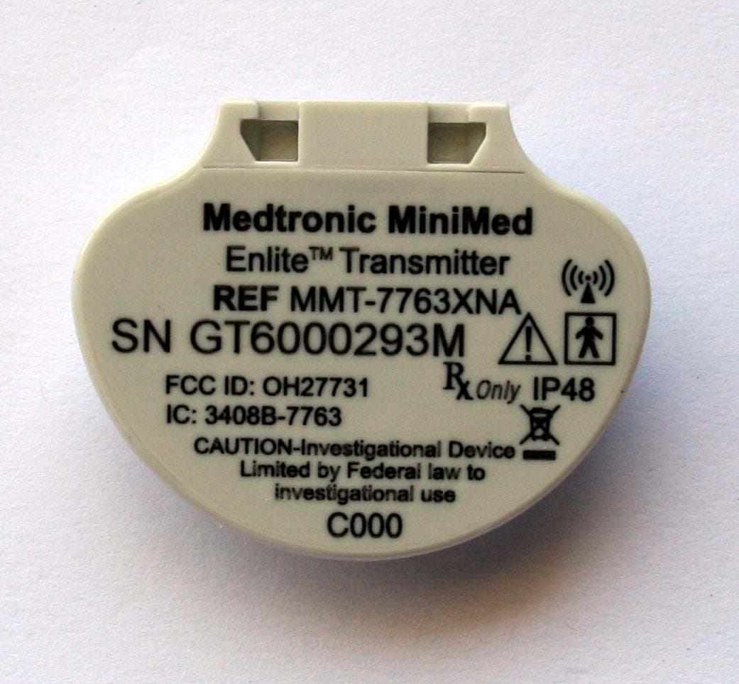
OH27731
Mar 10, 2015The Guardian Link transmitter is a component of the continuous glucose monitoring system for the MiniMed 600 series insulin pumps. The transmitter collects data from the glucose sensor and then wirelessly sends the data to the insulin pump.
Equipment Class
DTS - Digital Transmission System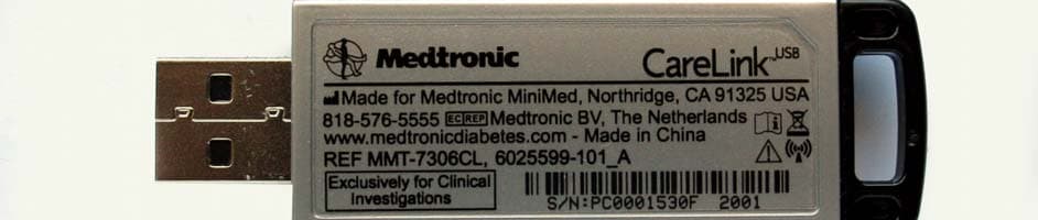
OH27306
Feb 08, 2015CareLINK USB
Equipment Class
DTS - Digital Transmission System
OH21510
Sep 24, 2014620G/630G/640G/670G Insulin Delivery Pump
Equipment Class
DTS - Digital Transmission System
OH27703
Apr 17, 2006Glucose Sensor Transmitter (GST1)
Equipment Class
DXX - Part 15 Low Power Communication Device Transmitter