OHKFMT-302Two Channel Remote Control TX
South Pacific Electronics Ltd.
Click to zoom
Application Details
- Equipment Class
- DXX - Part 15 Low Power Communication Device Transmitter
- Date of Grant
- Feb 14, 2000
- Application Purpose
- Original Equipment
- Date of Application
- Feb 02, 2000
- Equipment Note
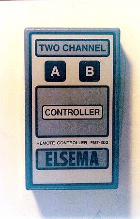
- Two Channel Remote Control TX
- Frequency Range
- 27.14500000 - 27.14500000
- Country
- Fiji
Documents & Files
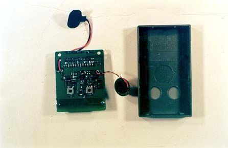
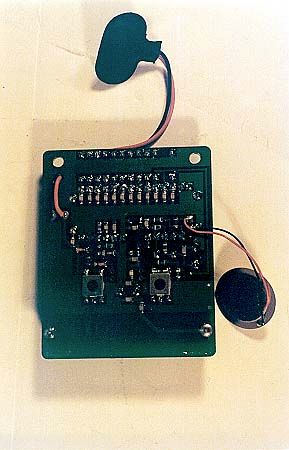
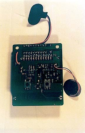
Document Text
Text extracted from the exhibit documents filed with the FCC. Open a document above to read the original.
Users Manual
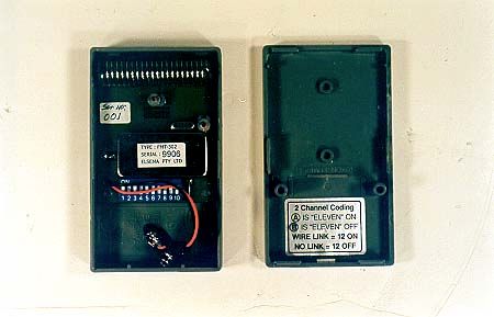
FMT-302 OPERATING MANUAL 27MHz 2-CHANNEL REMOTE CONTROL DIGITAL TRANSMITTER The hand controller, FMT-302 is part of a two-channel remote control system. A few of its applications could be as: The battery service life approximates its shelf life. 9-Volt Carbon or Alkaline type batteries may be used. Depending on the battery type, shelf life ranges between 1 and 2 years. While the FMT-302 is not transmitting it uses no power. It will operate on as low a 4 Volts DC, however, in such cases the power and range will be reduced. The highest possible standard of performance is achieved by employing a crystal-controlled, frequency modulated radio signal operating in the 27MHz band. This is enhanced by a specially dedicated custom-built integrated circuit. The latest "state of the art" surface-mount technology (SMD) provides maximum reliability. A 10-way code switch (part of the digital encoding system) is used. This enables the user to select any one of the 1024 available codes and thus ensure highest security against false operations. The eleventh switch is changed by pressing either channel A or B. The twelfth switch is “On” if a wire link is next to the code switch, if it is removed the twelveth switch is off. This is displayed on the back of the battery cover of the FMT-302. The code can be readily changed at any time. The maximum operating distance (in conjunction with our FMR series receivers) will average between 200 and 250 metres. The operating distance may depend upon the structure of the building in which it’s used. When operating near its range limit, some improvements may be obtained by pointing the controller towards the receiver. This is due to its slightly directional properties. In Australia, a licence issued under the "Wireless Telegraphy Act and Regulations" is not required for the operation of this transmitter. The housing of the controller has been designed to accept Elsema’s leather pockets. The controller is also available without its front membrane label, to enable the fitting of customers own designed label. • a calling device for the elderly or handicapped. • a personal security alarm activator for home safety or cash carrying businesses e.g. banks, shops service stations, etc. • a remote control switching device for garage doors, lights, gates and automatic telephone dialer. It is housed in an attractive, high impact resistant grey ABS plastic case. Pressing the designated switch on the front positively activates the controller. Activation is confirmed by the sound of its built- in buzzer. REGULATORY COMPIANCE STAEMENTS American Users This device complies with Part 15 of the FCC Rules. Operation is subject to the following two conditions: (1) This device may not cause harmful interference and (2) This device must accept any interference received, including interference that may cause undesired operation. FCC Notice This device has been tested and found to comply with the limits for a Class B digital device, pursuant to Part 15 of the FCC Rules. These limits are designed to provide reasonable protection against harmful interference in a residential installation. This device generates, uses, and can radiate radio frequency energy and, if installed and used in accordance with the instruction, may cause harmful interference to radio communications. However, there is no guarantee that interference will not occur in a particular installation. If this device does cause harmful interference to radio or television reception, the user is encouraged to try to correct the interference by one or more of the following measures: • Reorient or relocate the receiving antenna. • Increase the separation between the computer and receiver. • Connect the computer into an outlet on a circuit different from that to which the receiver is connected. • Consult the dealer or an experienced radio/TV technician for help. Caution: Any changes or modifications not expressly approved by the grantee of this device could void the user’s authority to operate the equipment. Canadian Users This Class [B] digital apparatus meets all requirements of the Canadian Interference-Causing Equipment Regulations. Cet appareil numérique de la classe [B] respecte toutes les exigences du Règlement sur le matériel brouilleur du Canada. European Users This information Technology Equipment has been tested and found to comply with the following European directives: - ETS 300 683 - I-ETS 300 220 Australian and New Zealand Users This device has been tested and found to comply with the limits for a Class [B] digital device, pursuant to the Australian/New Zealand standard AS 4268.2 (1995) set out by the Spectrum Management Agency. TECHNICAL DATA ON FMT-302 POWER SOURCE : 9-Volt Battery Carbon : approximately 1 year shelf life. Alkaline : approximately 2 year shelf life. SUPPLY VOLTAGE:6 to 16 VDC (For constant RF-Output). CURRENT CONSUMPTION :40mA (Typical) at 8VDC supply while transmitting OPERATING FREQUENCY :27.145MHz (Other frequencies available on 27.045, 27.195 and 27.455 MHz). CARRIER FREQUENCY TOLERANCE : Crystal controlled 30 parts per million (0 to 50° C). RADIATED R.F. POWER OUTPUT : 8.71 μW (CKC test result) ANTENNA :Built in 50mm proprietary DILEC rod. TYPE OF EMISSION :Narrow-band-width Frequency Modulation (5K00F1D) FREQUENCY DEVIATION :1600 Hz non-return to zero (+-20%). TYPE OF MODULATION : Manchester format 1.08ms per bit (15% tolerance). BITS PER SECOND926 bps SPURIOUS TRANSMISSION :Complies with FCC 15.227 (USA), MPT 1346 pt 4.5 (UK) and ETS 300 220 (Europe). NECESSARY BAND WIDTH :+ - 5.0 KHz DIGITAL CODING SYSTEM : On board 10-way coding switch (1024 codes) Channel "A" is equal to code-11 "on", Channel "B" is equal to code-11 "off" Wire Link is equal to code-12 "on" and No Link is equal to code-12 "off" (In receiver) DIMENSION :95 X 55 X 20 mm WEIGHT :72g excluding battery USEABLE OPERATING RANGE : up to 250 metres depending on building structure. COMPATIBLE RECEIVERS :All Elsema type FMR-... series. Due to…
Text truncated - open the document above for the full version.
Block Diagram
FMT-302 OPERATING MANUAL 27MHz 2-CHANNEL REMOTE CONTROL DIGITAL TRANSMITTER The hand controller, FMT-302 is part of a two-channel remote control system. A few of its applications could be as: The battery service life approximates its shelf life. 9-Volt Carbon or Alkaline type batteries may be used. Depending on the battery type, shelf life ranges between 1 and 2 years. While the FMT-302 is not transmitting it uses no power. It will operate on as low a 4 Volts DC, however, in such cases the power and range will be reduced. The highest possible standard of performance is achieved by employing a crystal-controlled, frequency modulated radio signal operating in the 27MHz band. This is enhanced by a specially dedicated custom-built integrated circuit. The latest "state of the art" surface-mount technology (SMD) provides maximum reliability. A 10-way code switch (part of the digital encoding system) is used. This enables the user to select any one of the 1024 available codes and thus ensure highest security against false operations. The eleventh switch is changed by pressing either channel A or B. The twelfth switch is “On” if a wire link is next to the code switch, if it is removed the twelveth switch is off. This is displayed on the back of the battery cover of the FMT-302. The code can be readily changed at any time. The maximum operating distance (in conjunction with our FMR series receivers) will average between 200 and 250 metres. The operating distance may depend upon the structure of the building in which it’s used. When operating near its range limit, some improvements may be obtained by pointing the controller towards the receiver. This is due to its slightly directional properties. In Australia, a licence issued under the "Wireless Telegraphy Act and Regulations" is not required for the operation of this transmitter. The housing of the controller has been designed to accept Elsema’s leather pockets. The controller is also available without its front membrane label, to enable the fitting of customers own designed label. • a calling device for the elderly or handicapped. • a personal security alarm activator for home safety or cash carrying businesses e.g. banks, shops service stations, etc. • a remote control switching device for garage doors, lights, gates and automatic telephone dialer. It is housed in an attractive, high impact resistant grey ABS plastic case. Pressing the designated switch on the front positively activates the controller. Activation is confirmed by the sound of its built- in buzzer. REGULATORY COMPIANCE STAEMENTS American Users This device complies with Part 15 of the FCC Rules. Operation is subject to the following two conditions: (1) This device may not cause harmful interference and (2) This device must accept any interference received, including interference that may cause undesired operation. FCC Notice This device has been tested and found to comply with the limits for a Class B digital device, pursuant to Part 15 of the FCC Rules. These limits are designed to provide reasonable protection against harmful interference in a residential installation. This device generates, uses, and can radiate radio frequency energy and, if installed and used in accordance with the instruction, may cause harmful interference to radio communications. However, there is no guarantee that interference will not occur in a particular installation. If this device does cause harmful interference to radio or television reception, the user is encouraged to try to correct the interference by one or more of the following measures: • Reorient or relocate the receiving antenna. • Increase the separation between the computer and receiver. • Connect the computer into an outlet on a circuit different from that to which the receiver is connected. • Consult the dealer or an experienced radio/TV technician for help. Caution: Any changes or modifications not expressly approved by the grantee of this device could void the user’s authority to operate the equipment. Canadian Users This Class [B] digital apparatus meets all requirements of the Canadian Interference-Causing Equipment Regulations. Cet appareil numérique de la classe [B] respecte toutes les exigences du Règlement sur le matériel brouilleur du Canada. European Users This information Technology Equipment has been tested and found to comply with the following European directives: - ETS 300 683 - I-ETS 300 220 Australian and New Zealand Users This device has been tested and found to comply with the limits for a Class [B] digital device, pursuant to the Australian/New Zealand standard AS 4268.2 (1995) set out by the Spectrum Management Agency. TECHNICAL DATA ON FMT-302 POWER SOURCE : 9-Volt Battery Carbon : approximately 1 year shelf life. Alkaline : approximately 2 year shelf life. SUPPLY VOLTAGE:6 to 16 VDC (For constant RF-Output). CURRENT CONSUMPTION :40mA (Typical) at 8VDC supply while transmitting OPERATING FREQUENCY :27.145MHz (Other frequencies available on 27.045, 27.195 and 27.455 MHz). CARRIER FREQUENCY TOLERANCE : Crystal controlled 30 parts per million (0 to 50° C). RADIATED R.F. POWER OUTPUT : 8.71 μW (CKC test result) ANTENNA :Built in 50mm proprietary DILEC rod. TYPE OF EMISSION :Narrow-band-width Frequency Modulation (5K00F1D) FREQUENCY DEVIATION :1600 Hz non-return to zero (+-20%). TYPE OF MODULATION : Manchester format 1.08ms per bit (15% tolerance). BITS PER SECOND926 bps SPURIOUS TRANSMISSION :Complies with FCC 15.227 (USA), MPT 1346 pt 4.5 (UK) and ETS 300 220 (Europe). NECESSARY BAND WIDTH :+ - 5.0 KHz DIGITAL CODING SYSTEM : On board 10-way coding switch (1024 codes) Channel "A" is equal to code-11 "on", Channel "B" is equal to code-11 "off" Wire Link is equal to code-12 "on" and No Link is equal to code-12 "off" (In receiver) DIMENSION :95 X 55 X 20 mm WEIGHT :72g excluding battery USEABLE OPERATING RANGE : up to 250 metres depending on building structure. COMPATIBLE RECEIVERS :All Elsema type FMR-... series. Due to…
Text truncated - open the document above for the full version.
Cover Letter(s)
11 th January, 2000 Federal Communications Commission 7435 Oakland Mills Road Columbia, MD 21046 Gentlemen: This is your letter of authorization to accept out appointment of CKC laboratories, Inc. as Agent for South Pacific Electronics, Lot 2 Haji Street Martintar Nadi Fiji Islands to sign applications before the Commission on our behalf, and to receive and exchange data between our company and the commission in connection with certification of the following South Pacific Electronics product: Elsema FMT-302 transmitter We, the applicant certify that, in the case of individual applicant, he or she is not subject to a denial of federal benefits pursuant to section 5301 of the Anti- Drug Abuse Act of 1988, 21 USC 853a or in the case of non-individual applicant (e.g. corporation, partnership or other unincorporated association), no party to the applicant is subject to a denial of federal benefit pursuant to that action. This authorization will expire one year from the date of this letter. Sincerely, Richard Eigner Managing Director
ID Label/Location Info
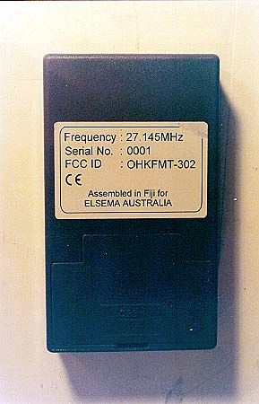
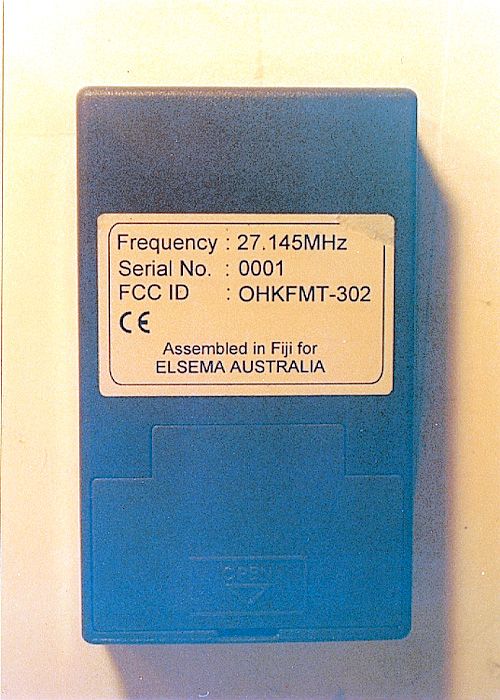
Assembled in Fiji for ELSEMA AUSTRALIA Serial No.: Frequency : 27.145MHz 0001 OHKFMT-302 FCC ID : 49.0mm 31.0mm Sample ID label for FMT-302 Material: White, 80 or 90 grammes writing paper coated with strong, permanent adhesive. After the label has been affixed, it will not be possible to remove it without tearing it. Print is black. Placement: Label will be place on the rear cover approximately 20mm from the top. Complies with the limits for a Class [B] digital device, pursuant to the Australian/New Zealand standard.
Operational Description
FMT-302 OPERATING MANUAL 27MHz 2-CHANNEL REMOTE CONTROL DIGITAL TRANSMITTER The hand controller, FMT-302 is part of a two-channel remote control system. A few of its applications could be as: The battery service life approximates its shelf life. 9-Volt Carbon or Alkaline type batteries may be used. Depending on the battery type, shelf life ranges between 1 and 2 years. While the FMT-302 is not transmitting it uses no power. It will operate on as low a 4 Volts DC, however, in such cases the power and range will be reduced. The highest possible standard of performance is achieved by employing a crystal-controlled, frequency modulated radio signal operating in the 27MHz band. This is enhanced by a specially dedicated custom-built integrated circuit. The latest "state of the art" surface-mount technology (SMD) provides maximum reliability. A 10-way code switch (part of the digital encoding system) is used. This enables the user to select any one of the 1024 available codes and thus ensure highest security against false operations. The eleventh switch is changed by pressing either channel A or B. The twelfth switch is “On” if a wire link is next to the code switch, if it is removed the twelveth switch is off. This is displayed on the back of the battery cover of the FMT-302. The code can be readily changed at any time. The maximum operating distance (in conjunction with our FMR series receivers) will average between 200 and 250 metres. The operating distance may depend upon the structure of the building in which it’s used. When operating near its range limit, some improvements may be obtained by pointing the controller towards the receiver. This is due to its slightly directional properties. In Australia, a licence issued under the "Wireless Telegraphy Act and Regulations" is not required for the operation of this transmitter. The housing of the controller has been designed to accept Elsema’s leather pockets. The controller is also available without its front membrane label, to enable the fitting of customers own designed label. • a calling device for the elderly or handicapped. • a personal security alarm activator for home safety or cash carrying businesses e.g. banks, shops service stations, etc. • a remote control switching device for garage doors, lights, gates and automatic telephone dialer. It is housed in an attractive, high impact resistant grey ABS plastic case. Pressing the designated switch on the front positively activates the controller. Activation is confirmed by the sound of its built- in buzzer. REGULATORY COMPIANCE STAEMENTS American Users This device complies with Part 15 of the FCC Rules. Operation is subject to the following two conditions: (1) This device may not cause harmful interference and (2) This device must accept any interference received, including interference that may cause undesired operation. FCC Notice This device has been tested and found to comply with the limits for a Class B digital device, pursuant to Part 15 of the FCC Rules. These limits are designed to provide reasonable protection against harmful interference in a residential installation. This device generates, uses, and can radiate radio frequency energy and, if installed and used in accordance with the instruction, may cause harmful interference to radio communications. However, there is no guarantee that interference will not occur in a particular installation. If this device does cause harmful interference to radio or television reception, the user is encouraged to try to correct the interference by one or more of the following measures: • Reorient or relocate the receiving antenna. • Increase the separation between the computer and receiver. • Connect the computer into an outlet on a circuit different from that to which the receiver is connected. • Consult the dealer or an experienced radio/TV technician for help. Caution: Any changes or modifications not expressly approved by the grantee of this device could void the user’s authority to operate the equipment. Canadian Users This Class [B] digital apparatus meets all requirements of the Canadian Interference-Causing Equipment Regulations. Cet appareil numérique de la classe [B] respecte toutes les exigences du Règlement sur le matériel brouilleur du Canada. European Users This information Technology Equipment has been tested and found to comply with the following European directives: - ETS 300 683 - I-ETS 300 220 Australian and New Zealand Users This device has been tested and found to comply with the limits for a Class [B] digital device, pursuant to the Australian/New Zealand standard AS 4268.2 (1995) set out by the Spectrum Management Agency. TECHNICAL DATA ON FMT-302 POWER SOURCE : 9-Volt Battery Carbon : approximately 1 year shelf life. Alkaline : approximately 2 year shelf life. SUPPLY VOLTAGE:6 to 16 VDC (For constant RF-Output). CURRENT CONSUMPTION :40mA (Typical) at 8VDC supply while transmitting OPERATING FREQUENCY :27.145MHz (Other frequencies available on 27.045, 27.195 and 27.455 MHz). CARRIER FREQUENCY TOLERANCE : Crystal controlled 30 parts per million (0 to 50° C). RADIATED R.F. POWER OUTPUT : 8.71 μW (CKC test result) ANTENNA :Built in 50mm proprietary DILEC rod. TYPE OF EMISSION :Narrow-band-width Frequency Modulation (5K00F1D) FREQUENCY DEVIATION :1600 Hz non-return to zero (+-20%). TYPE OF MODULATION : Manchester format 1.08ms per bit (15% tolerance). BITS PER SECOND926 bps SPURIOUS TRANSMISSION :Complies with FCC 15.227 (USA), MPT 1346 pt 4.5 (UK) and ETS 300 220 (Europe). NECESSARY BAND WIDTH :+ - 5.0 KHz DIGITAL CODING SYSTEM : On board 10-way coding switch (1024 codes) Channel "A" is equal to code-11 "on", Channel "B" is equal to code-11 "off" Wire Link is equal to code-12 "on" and No Link is equal to code-12 "off" (In receiver) DIMENSION :95 X 55 X 20 mm WEIGHT :72g excluding battery USEABLE OPERATING RANGE : up to 250 metres depending on building structure. COMPATIBLE RECEIVERS :All Elsema type FMR-... series. Due to…
Text truncated - open the document above for the full version.
Schematics
1 28 2 27 3 26 4 25 5 24 6 23 7 22 8 21 9 20 10 19 11 18 12 17 13 16 14 15 ERIC 47K 470 W 470K 1K 10K 10K 10K 9V Battery (6-16V) FMT-302 Circuit Diagram 1Hm 22pF 3pF 33pF33pF 15pF 56pF 50mm DILEC antenna 270pF Buzzer MA73 22pF 15pF Crystal 27.145MHz 33pF 15pF 10 Way Code Switch 220W BC817 BC817 BZT55-C6V2 100nF 1nF 12 1nF 1nF Link LS4148 LS4148
Test Report
Page 1 of 20 Report No: FC00-007 CERTIFICATION TEST REPORT FOR THE 27.145 MHZ TRANSMITTER, FMT-302 FCC PART 15 SUBPART C COMPLIANCE DATE OF ISSUE: DECEMBER 20, 1999 PREPARED FOR: Elsema Pty Ltd Unit 3, 10 Hume Road Smithfield 2164 Australia W.O. No: 71920 PREPARED BY: Joyce Walker CKC Laboratories, Inc. 5473A Clouds Rest Mariposa, CA 95338 Date of test: August 5 & December 23, 1999 Report No: FC00-007 DOCUMENTATION CONTROL: _____________________________ Tracy Phillips Documentation Control Supervisor CKC Laboratories, Inc. APPROVED BY: _____________________________ Dennis Ward Director of Laboratories CKC Laboratories, Inc. This report contains a total of 20pages and may be reproduced in full only. Partial reproduction may only be done with the written consent of CKC Laboratories, Inc. Page 2 of 20 Report No: FC00-007 TABLE OF CONTENTS Administrative Information..........................................................................................3 Summary Of Results....................................................................................................4 Equipment Under Test (EUT) Description...................................................................4 Measurement Uncertainty............................................................................................4 Peripheral Devices.......................................................................................................4 Report Of Measurements.............................................................................................5 Table 1: Fundamental Radiated Emission Levels.............................................5 Table 2: Six Highest Spurious Emission Levels...............................................6 Table A : List Of Test Equipment................................................................................7 EUT Setup...................................................................................................................8 Test Instrumentation And Analyzer Settings................................................................8 Table B : Analyzer Bandwidth Settings Per Frequency Range..........................8 Spectrum Analyzer Detector Functions.............................................................9 Peak......................................................................................................9 Quasi-Peak............................................................................................9 Average................................................................................................9 Test Methods...............................................................................................................10 Radiated Emissions Testing..............................................................................10 Occupied Bandwidth........................................................................................11 Sample Calculations.....................................................................................................12 Appendix A : Information About The Equipment Under Test......................................13 I/O Ports...........................................................................................................14 Crystal Oscillators............................................................................................14 Printed Circuit Boards......................................................................................14 Required EUT Changes To Comply..................................................................14 Photograph Showing Radiated Emissions.........................................................15 Appendix B : Measurement Data Sheets......................................................................16 Occupied Bandwidth Plot Part 15.215..............................................................17 Page 3 of 20 Report No: FC00-007 CKC Laboratories, Inc. has Certificates of Accreditation from the following agencies: DATech (Germany); A2LA (USA); FCC (USA); VCCI (Japan); BSMI (Taiwan); HOKLAS (Hong Kong). CKC Laboratories, Inc. has Letters of Acceptance through an MRA for the following agencies: ACA/NATA (Australia); SABS (South Africa); SWEDAC (Sweden); TUV Rheinland-Germany; TUV Rheinland- Korea; TUV Rheinland-Russia; Radio Communication Agency (RA); NEMKO (Norway). ADMINISTRATIVE INFORMATION DATE OF TEST: August 5 & December 23, 1999 PURPOSE OF TEST: To demonstrate the compliance of the 27.145 MHz Transmitter, FMT-302, with the requirements for FCC Part 15 Subpart C devices. MANUFACTURER: Elsema Pty Ltd Unit 3, 10 Hume Road Smithfield 2164 Australia REPRESENTATIVE: Hermann Roesch TEST LOCATION: CKC Laboratories, Inc. 5473A Clouds Rest Mariposa, CA 95338 TEST PERSONNEL: Skip Doyle & Craig Mullis TEST METHOD: ANSI C63.4 1992 FREQUENCY RANGE TESTED: 27-1000 MHz EQUIPMENT UNDER TEST:27.145 MHz Transmitter Manuf: South Pacific Electronics LTD. Model: FMT302 Serial: 001 FCC ID: OHKFMT-302 (pending) Page 4 of 20 Report No: FC00-007 SUMMARY OF RESULTS The Elsema Pty Ltd 27.145 MHz Transmitter, FMT-302, was tested in accordance with ANSI C63.4 1992 for compliance with FCC Part 15 Subpart C. As received, the above equipment was found to be fully compliant with the limits of FCC Part 15 Subpart C. The results in this report apply only to the items tested, as identified herein. EQUIPMENT UNDER TEST (EUT) DESCRIPTION Two channel 27MHz hand held remote control digital transmitter. Note: The customer user manual refers to multiple channels. Only the one channel reflected in this test report will be sold in the United States. The other channels are for different countries. A different channel is selected by using a different crystal and is done during the manufacturing stage. The consumer cannot change the transmitter to a different channel. MEASUREMENT UNCERTAINTY Associated with data in this report is a ±4dB measurement uncertainty. PERIPHERAL DEVICES The EUT was not tested w…
Text truncated - open the document above for the full version.
Contact Information
Applicant
Richard Eigner(Managing Director)
Technical Contact
CKC Laboratories, Inc.Tracy Phillips
[email protected]1-800-500-4362
5473A Clouds Rest · Mariposa, California · United States
Non-Technical Contact
CKC Laboratories, Inc.Joyce Walker
[email protected]1-800-500-4362
Test Firm
CKC Laboratories, Inc.Steve Behm
Technical Specifications
| # | Rule Parts | Frequency Range | Power Output |
|---|---|---|---|
| 1 | 15C | 27.145 MHz - 27.145 MHz | - |
Other Applications from South Pacific Electronics Ltd.
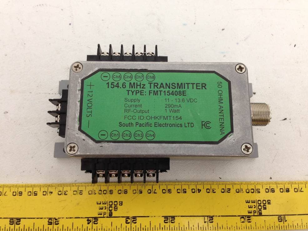
OHKFMT154
Mar 21, 2013154.6 MHz Transmitter
Equipment Class
TNB - Licensed Non-Broadcast Station Transmitter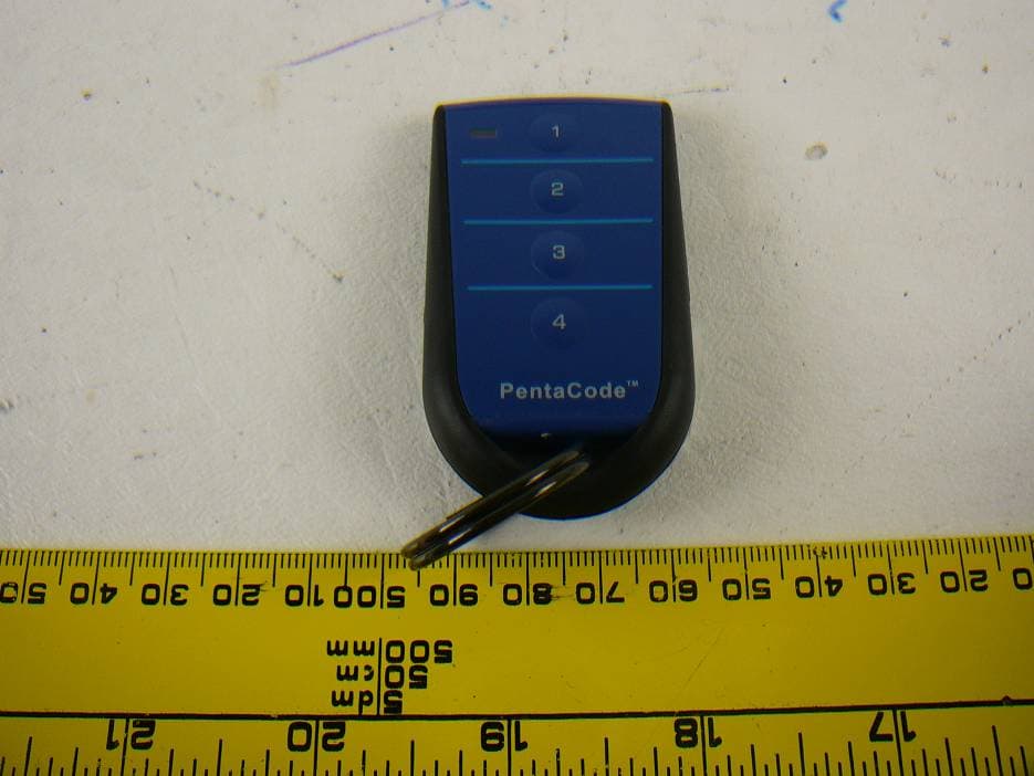
OHKPCK433
Oct 30, 20124 Button Keyring Remote Control, PCK43304
Equipment Class
DSC - Part 15 Security/Remote Control Transmitter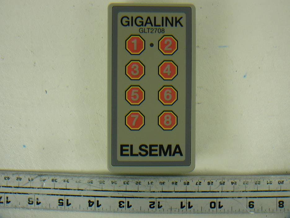
OHKGLT2708
Jun 07, 20128 Channel Hand Held 27MHz Transmitter, GLT2708
Equipment Class
DXX - Part 15 Low Power Communication Device Transmitter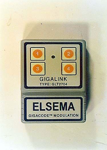
OHKGLT2704
Mar 13, 200027MHz Handheld Gigalink Transmitter, Model GLT270X
Equipment Class
DXX - Part 15 Low Power Communication Device Transmitter
OHKFMT-301
Sep 06, 1999DXX - Part 15 Low Power Communication Device Transmitter
Equipment Class
DXX - Part 15 Low Power Communication Device Transmitter