OHKGLT27088 Channel Hand Held 27MHz Transmitter, GLT2708
South Pacific Electronics Ltd.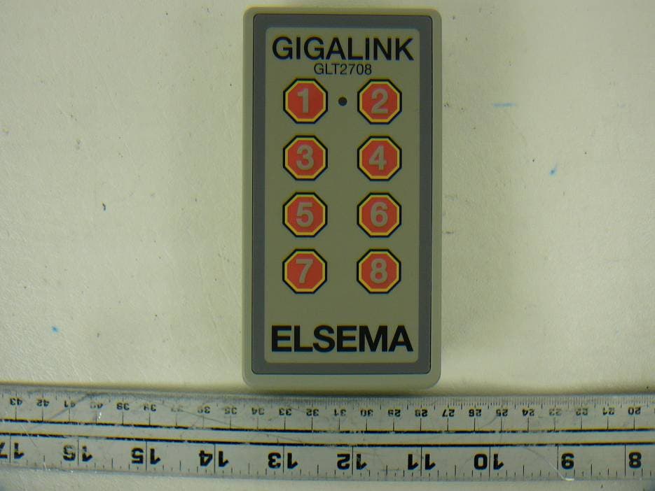
Click to zoom
Application Details
- Equipment Class
- DXX - Part 15 Low Power Communication Device Transmitter
- Date of Grant
- Jun 07, 2012
- Application Purpose
- Original Equipment
- Date of Application
- Jun 07, 2012
- Equipment Note
- 8 Channel Hand Held 27MHz Transmitter, GLT2708
- Frequency Range
- 27.19500000 - 27.19500000
- Country
- Fiji
Documents & Files
Document Text
Text extracted from the exhibit documents filed with the FCC. Open a document above to read the original.
Users Manual
ELSEMA 1,2,3,4,8 -Channel 27MHz GIGALINK™ Transmitter GLT2700,GLT2701,GLT2702,GLT2703,GLT2704,GLT2708 GLT2700, GLT2701, GLT2702, GLT2703, GLT2704 and GLT2708 27MHz HAND HELD GIGALINK™TRANSMITTERS Features • Over 4 billion code combinations • Can program any number of transmitters to a receiver • High Security Applications • Remote control of garage doors, gates, lights, alarms Description The hand held GIGALINK™ transmitters are the most advanced Remote Control technology available in the world today. GIGALINK™ is an invention that has revolutionised the entire Remote Control technology including Elsema's earlier version of FMT- ... and FMR- ... series. The GLT2700/1/2/3/4/8 state-of-the-art invention brings a new dimension in the world of Remote Control technology in domestic, commercial and industrial applications. The innovative microcontroller technology replaces the traditional dip switch coding which eliminates any possible code grabbing. Special features such as over four billion code combinations and the ability to program any number of transmitters to a receiver, adds to the most advanced and secure Remote Controls available. The hand held GIGALINK™ transmitters have a microcontroller in-built single and channelised code programming system that provides flexibility in programming each channel to different receivers. Each transmitter can store to its EEPROM, up to four random channels allowing the user to program each channel from different single channel receivers. This is achieved when single code programming the transmitter channels from a GLR2701, which is a single channel GIGALINK™ receiver. If the transmitter is single code programmed from a multi channel receiver, the selected receiver's channel is programmed to the selected transmitter channel. The channels can be selected by using the dip switches on the receiver and by pressing the appropriate channel button on the transmitter. Channelised code programming programs all the channels, from a multi channel receiver, to the multi channel transmitter. That is, channel one on the transmitter activates channel one on the receiver and alternatively. Channelised system can be either used as simple on/off functions or for several channels to operate simultaneously such as dual or multi action control for example crane transmission control. The transmitter can be single or channelised code programmed without power connected. Single Code Programming This is used for programming one channel at a time to the transmitter. To single code program a transmitter read receivers setup instructions. Channelised Code Programming This is used to program all channels from a multi channel receiver to the multi channel transmitter. To channelise code program a transmitter read receivers setup instructions. ELSEMA 1,2,3,4,8 -Channel 27MHz GIGALINK™ Transmitter GLT2700,GLT2701,GLT2702,GLT2703,GLT2704,GLT2708 Operating Distance An operating distance (in conjunction with our GLR27 series receivers) of 350 metres is possible. The operating distance depends upon the receiver antenna and location. An independent test revealed the following ranges: Range (Metres) Receiver Antenna Receiver Type 50 250 mm Long Wire GLR27.... 200 1000 mm Long Wire GLR27.... 350 ANT27M GLR27.... Range tests were done in an open area test site with line-of-sight operation and the receiver antenna wire was fixed vertically, away from any metal objects. Applications The code programming becomes a powerful feature that allows the hand held transmitters to be used in many diverse applications such as security, gate operation, panic buttons, multiple on/off functions etc. Battery or DC Supply Battery operation is optimised using the built-in battery monitoring system. The battery monitoring system alerts the user when the battery level falls below the low battery voltage. The 1 Hz flash from the LED during a transmission indicates low battery. This is an indication that replacement of a battery is necessary. The GLT2708NC has the option to operate from a 9-volt battery or DC power supply. DC power supply is connected to the 2-way terminal block. Do not connect the supply to the 2.5-mm coding socket since connection may damage the microcontroller. Also available with a 5-Pin header for inputs. Channels The hand held transmitters are available with 1, 2, 3, 4 and 8 channels. Custom made front Membrane Membrane is the front label with the channel etched/printed to it. Customers can purchase the GLT2700, which is a hand held GIGALINK™ transmitter without the front membrane. This enables the customers to fit their custom made membrane that can be a 1, 2, 3 or 4 channels. This has the advantage of customers only stocking one model to function as a 1, 2, 3 and 4 channels. Details of membrane dimensions are given on the following page. Customers can even use Elsema's membrane tools to manufacture their own membranes. The GLT2708 is also available without membrane, allowing customers to stick their own custom made membranes. Part number is GLT2708NL Unique Code System The microcontroller EEPROM allows large volume users to have a unique code. This enables Elsema to offer everyone “your own” radio control. Case The hand held GIGALINK™ transmitters are supplied with a case. There is also sufficient space on the rear of the case to place additional stickers such as your telephone contact, local authorities approval numbers etc. The GLT2700NC and GLT2708NC are No Case versions. This allows the transmitter to be integrated according to your needs. ELSEMA 1,2,3,4,8 -Channel 27MHz GIGALINK™ Transmitter GLT2700,GLT2701,GLT2702,GLT2703,GLT2704,GLT2708 Products in the Range GLT2700 Transmitter GLT2701 1-Channel GLT2702 2-Channel GLT2703 3-Channel GLT2704 4-Channel NL: No label The Elsema Label is absent. GLT2708 8-Channel GLT2716 2-Stroke, 16-Channel GLT2700NC Transmitter, No Case Option Pin header GLT2708NC 8-Channel, No Case ELSEMA 1,2,3,4,8 -Channel 27MHz GIGALINK™ Transmitter GLT2700,GLT2701,GLT…
Text truncated - open the document above for the full version.
Cover Letter(s)
FCC Confidential Authorization 17ft May 2012 FEDE,RAL COMMLINICATTONS COMMISSIONS Authorization and Evaluation Division 7435 Oakland Mills Road Columbia, MD 21446 Subject: Confidentiality Request regarding application for certification of FCC ID: OHKGLT2TOS In accordance with Sections 0.457 and 0.459 of the Commission's Rules, South Pacific Electronics Ltd hereby requests long-term confidential treatment of information accompanying this application as outlined below: o Block Diagram r Schematics . OperationDescription The above materials contain proprietary and confidential information not customarily released to the public. The public disclosure of these materials provides unjustified benefits to its competitors in the market. Sincerely, -)4 //. tn% Richard4isner Director First Electronic Manufactur"ing Company in the South Pacific
External Photos
South Pacific Electronics Ltd. FCC ID: OHKGLT2708 Report Number: R1204231-227 Page 16 of 20 FCC Part 15.227 Test Report 7 Exhibit C - EUT Photographs 7.1 EUT - Front View 7.2 EUT – Back View South Pacific Electronics Ltd. FCC ID: OHKGLT2708 Report Number: R1204231-227 Page 17 of 20 FCC Part 15.227 Test Report 7.3 EUT - Top View 7.4 EUT – Bottom View South Pacific Electronics Ltd. FCC ID: OHKGLT2708 Report Number: R1204231-227 Page 18 of 20 FCC Part 15.227 Test Report 7.5 EUT – Side View 1 7.6 EUT – Side View 2
Internal Photos
South Pacific Electronics Ltd. FCC ID: OHKGLT2708 Report Number: R1204231-227 Page 19 of 20 FCC Part 15.227 Test Report 7.7 EUT – Battery off View 7.8 EUT – Cover off view South Pacific Electronics Ltd. FCC ID: OHKGLT2708 Report Number: R1204231-227 Page 20 of 20 FCC Part 15.227 Test Report 7.9 EUT – Top PCB View 7.10 EUT – Bottom PCB View --- END OF REPORT --- Antenna
Test Report
Note: This test report is prepared for the customer shown above and for the device described herein. It may not be duplicated or used in part without prior written consent from Bay Area Compliance Laboratories Corp. This report must not be used by the customer to claim product certification, approval, or endorsement by A2LA* or any agency of the Federal Government. * This report may contain data that are not covered by the A2LA accreditation and are marked with an asterisk “*” (Rev.3) FCC PART 15.227 TEST AND MEASUREMENT REPORT For South Pacific Electronics Ltd. P.O. Box 9417, Nadi Airport, Nadi, Fiji FCC ID: OHKGLT2708 Report Type: Original Report Product Type: 27 MHz Remote Control Transmitter Prepared By: Lionel Lara Report Number: R1204231-227 Report Date: 2012-05-30 Reviewed By: Victor Zhang RF/EMC Lead Bay Area Compliance Laboratories Corp. 1274 Anvilwood Avenue, Sunnyvale, CA 94089, USA Tel: (408) 732-9162 Fax: (408) 732 9164 South Pacific Electronics Ltd. FCC ID: OHKGLT2708 Report Number: R1204231-227 Page 2 of 20 FCC Part 15.227 Test Report TABLE OF CONTENTS 1. General Information.............................................................................................................................................4 1.1 PRODUCT DESCRIPTION FOR EQUIPMENT UNDER TEST (EUT) ........................................................................4 1.2 MECHANICAL DESCRIPTION............................................................................................................................4 1.3 OBJECTIVE......................................................................................................................................................4 1.4 RELATED SUBMITTAL(S)/GRANT(S)................................................................................................................4 1.5 TEST METHODOLOGY.....................................................................................................................................4 1.6 MEASUREMENT UNCERTAINTY.......................................................................................................................4 1.7 TEST FACILITY................................................................................................................................................5 2 System Test Configuration...................................................................................................................................6 2.1 JUSTIFICATION................................................................................................................................................6 2.2 EUT EXERCISE SOFTWARE.............................................................................................................................6 2.3 EQUIPMENT MODIFICATIONS..........................................................................................................................6 2.4 INTERNAL CONFIGURATION............................................................................................................................6 2.5 LOCAL SUPPORT EQUIPMENT..........................................................................................................................6 2.6 EXTERNAL I/O CABLING LIST AND DETAILS..................................................................................................6 3 Summary of Test Results......................................................................................................................................7 FCC §15.203 – Antenna Description............................................................................................................................8 3.1 APPLICABLE STANDARD.................................................................................................................................8 3.2 ANTENNA CONNECTOR CONSTRUCTION.........................................................................................................8 4 FCC §15.209 & §15.227 – Radiated Emissions...................................................................................................9 4.1 APPLICABLE STANDARD.................................................................................................................................9 4.2 TEST SETUP....................................................................................................................................................9 4.3 TEST PROCEDURE.........................................................................................................................................10 4.4 CORRECTED AMPLITUDE & MARGIN CALCULATION....................................................................................10 4.5 TEST EQUIPMENT LIST AND DETAILS............................................................................................................11 4.6 TEST ENVIRONMENTAL CONDITIONS............................................................................................................11 4.7 SUMMARY OF TEST RESULTS........................................................................................................................11 4.8 RADIATED EMISSIONS TEST RESULT DATA..................................................................................................12 5 Exhibit A - FCC Equipment Labeling Requirements......................................................................................13 5.1 FCC LABEL REQUIREMENTS.........................................................................................................................13 5.2 FCC ID LABEL CONTENTS AND LOCATION..................................................................................................13 6 Exhibit B - Test Setup Photographs ..................................................................................................................14 6.1 RADIATED EMISSION – FRONT VIEW............................................................…
Text truncated - open the document above for the full version.
Test Setup Photos
South Pacific Electronics Ltd. FCC ID: OHKGLT2708 Report Number: R1204231-227 Page 14 of 20 FCC Part 15.227 Test Report 6 Exhibit B - Test Setup Photographs 6.1 Radiated Emission – Front View 6.2 Radiated Emission below 30 MHz – Rear View South Pacific Electronics Ltd. FCC ID: OHKGLT2708 Report Number: R1204231-227 Page 15 of 20 FCC Part 15.227 Test Report 6.3 Radiated Emissions above 30 MHz – Rear View
Contact Information
Applicant
Richard Eigner(Managing Director)
Test Firm
Bay Area Compliance Laboratories Corp.Lisa Tang
Technical Specifications
| # | Rule Parts | Frequency Range | Power Output |
|---|---|---|---|
| 1 | 15C | 27.195 MHz - 27.195 MHz | - |
Other Applications from South Pacific Electronics Ltd.
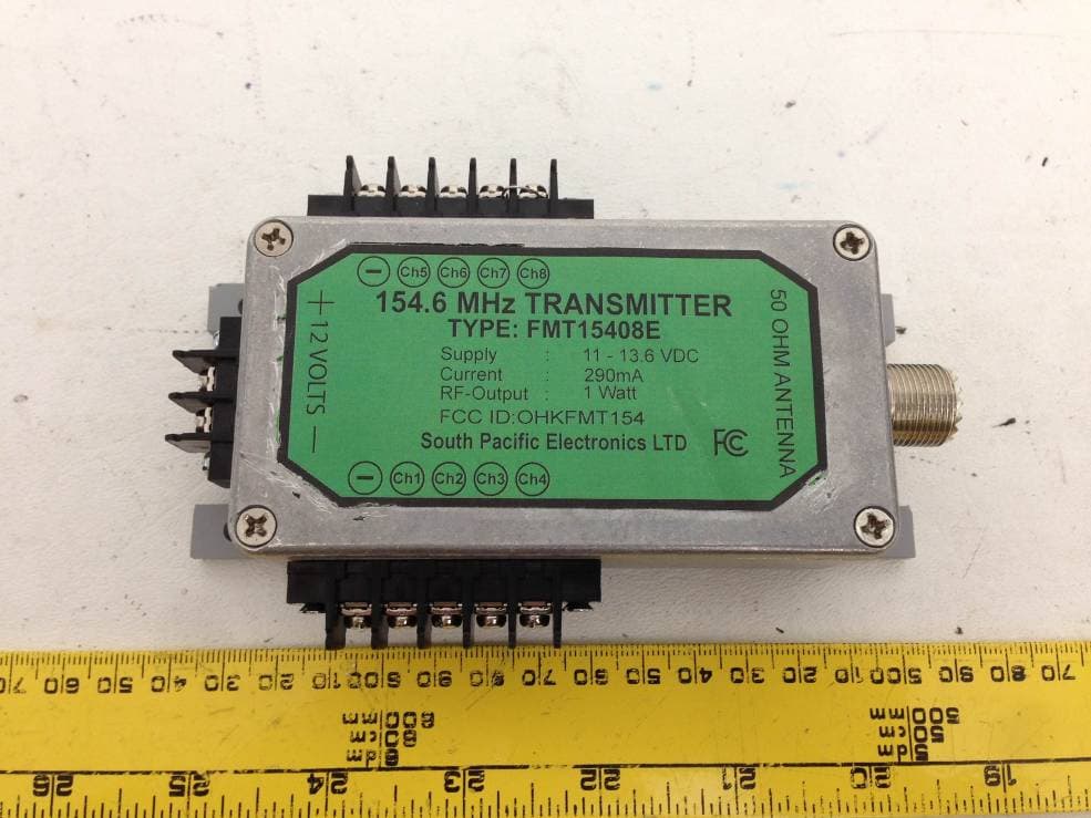
OHKFMT154
Mar 21, 2013154.6 MHz Transmitter
Equipment Class
TNB - Licensed Non-Broadcast Station Transmitter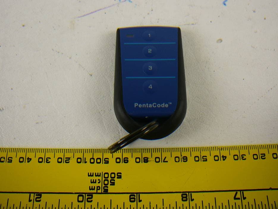
OHKPCK433
Oct 30, 20124 Button Keyring Remote Control, PCK43304
Equipment Class
DSC - Part 15 Security/Remote Control Transmitter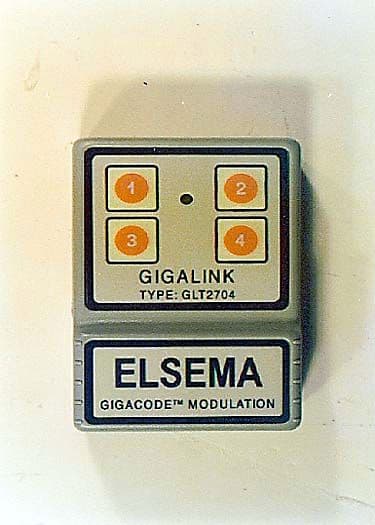
OHKGLT2704
Mar 13, 200027MHz Handheld Gigalink Transmitter, Model GLT270X
Equipment Class
DXX - Part 15 Low Power Communication Device Transmitter
OHKFMT-302
Feb 14, 2000Two Channel Remote Control TX
Equipment Class
DXX - Part 15 Low Power Communication Device Transmitter
OHKFMT-301
Sep 06, 1999DXX - Part 15 Low Power Communication Device Transmitter
Equipment Class
DXX - Part 15 Low Power Communication Device Transmitter