OHT692427AARKE Transmitter
Strattec Security Corporation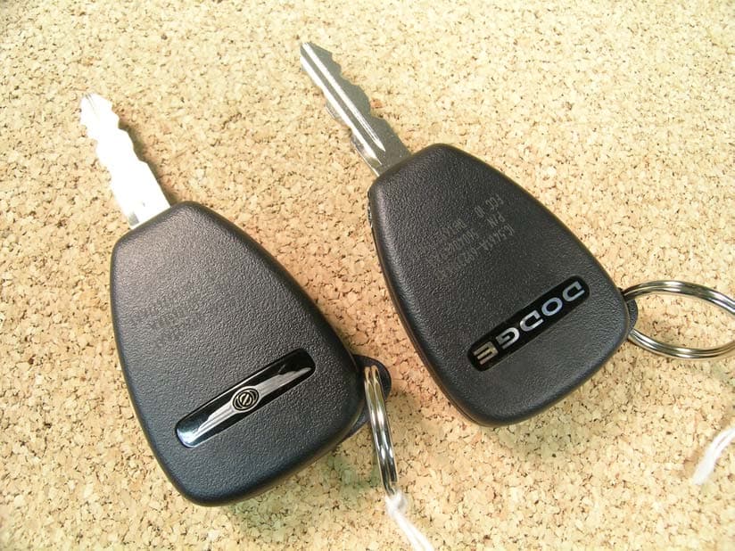
Click to zoom
Application Details
- Equipment Class
- DSC - Part 15 Security/Remote Control Transmitter
- Date of Grant
- May 07, 2005
- Application Purpose
- Original Equipment
- Date of Application
- May 07, 2005
- Equipment Note
- RKE Transmitter
- Frequency Range
- 315.00000000 - 315.00000000
- Country
- United States
Documents & Files
Document Text
Text extracted from the exhibit documents filed with the FCC. Open a document above to read the original.
Users Manual
Re: Certification for Strattec Transmitter PN(s): 56040652AB, 56040669AB, 56040649AB, 05026134AA FCC ID: OHT692427AA IC: 5461A-692427AA USER'S MANUAL INFORMATION (PRELIMINARY) The User's Manual is in preparation. The following material will be contained in the manual: FCC ID: OHT692427AA IC: 5461A-692427AA This device complies with Part 15 of the FCC Rules and with RSS-210 of Industry Canada. Operation is subject to the following two conditions: (1) This device may not cause harmful interference, and (2) This device must accept any interference received, including interference that may cause undesired operation. WARNING: Changes or modifications not expressively approved by the party responsible for compliance could void the user's authority to operate the equipment. The term “IC:” before the radio certification number only signifies that Industry Canada technical specifications were met.
Attestation Statements
Re: Certification for Strattec Transmitter PN(s): 56040652AB, 56040669AB, 56040649AB, 05026134AA FCC ID: OHT692427AA IC: 5461A-692427AA POWER OF ATTORNEY A letter granting Valdis V. Liepa the Power of Attorney is on file and can be provided when so requested. Re: Certification for Strattec Transmitter PN(s): 56040652AB, 56040669AB, 56040649AB, 05026134AA FCC ID: OHT692427AA IC: 5461A-692427AA REQUEST FOR CONFIDENTIALITY Pursuant to 47 CRF 0.459, Strattec requests that a part of the subject application be held confidential. This comprises Exhibits (5) Schematics (10) Parts List (Part of Exhibit only) Strattec has spent substantial effort in developing this product and it is one of the first of its kind in industry. Having the subject information easily available to "competition" would negate the advantage they have achieved by developing this product. Not protecting the details of the design will result in financial hardship. If there are any questions regarding this request, please contact me at the above address or call 734-483-4211, fax 734-647-2106 or e-mail [email protected]. Sincerely, Valdis V. Liepa Research Scientist University of Michigan May 5, 2005 Re: Certification for Strattec Transmitter PN(s): 56040652AB, 56040669AB, 56040649AB, 05026134AA FCC ID: OHT692427AA IC: 5461A-692427AA STATEMENT OF MODIFICATIONS There were no modifications made to the DUT by this test laboratory. (Also see Section 3.1 of the attached Test Report). _____________________ Valdis V. Liepa Research Scientist Re: Certification for Strattec Transmitter PN(s): 56040652AB, 56040669AB, 56040649AB, 05026134AA FCC ID: OHT692427AA IC: 5461A-692427AA GENERAL PRODUCT INFORMATION The device, for which certification is pursued, has been designed by: Strattec Security Corporation Milwaukee, Wisconsin 53209 3333 West Good Hope Road Bill Lusa Tel: (734) 484-1387 Fax: (734) 484-1389 It will be manufactured by: Strattec Security Corporation 3333 West Good Hope Road Milwaukee, Wisconsin 53209 Bill Lusa Tel: (734) 484-1387 Fax: (734) 484-1389 Canadian Contact: Shield Supply & Service Mr. E. Wiechman 1391 St. James St., Unit 17 Winnipeg, MB R3H 0Z1 CANADA Phone 204-774-1921
Block Diagram
DCX Corproate PCB block diagram and system operation Fob Block Diagram The fob has the following sections: Power Supply, User Interfaces, Microcontroller (STARC2XL), RF Antenna, LF Antenna and a RF circuit. The following block diagram gives a visual representation of the relationship of these sections. General The Daimler Chrysler Corporate PCB is an interface for the customer to communicate with the vehicle's DaimlerChrysler Wireless Control Module (WCM). It combines normal RKE function and transponder functions in a single unit. The Corporate PCB consists of a circuit board and circuit components. The conventional metal key blade which is used to start and unlock doors is molded in the upper housing of the FOB. The Corporate FOB also has Key Pad Polydome Switches on the top surface of the assembly. Pressing the FOB polydome switches will result in the FOB sending the following RF signals to the WCM: Lock doors Unlock doors Activate the vehicle horn in a PANIC mode Open a trunk, lift gate, or flipper glass Open Sliding Doors Remote Start / Kill (unique button sequences) The Corporate PCB also provide the immobilizer function through LF circuit providing: Transponder Functionality (North American and European models only) The Corporate PCB (internal to housing) can be used for Remote Keyless Entry (RKE) via 315MHz ( North American and Japan) and 433.92MHz (European) radio frequency (RF) and for immobilizer functionality via a 125KHz low frequency (LF). The RF link is comprised of a control module (WCM), containing a receiver, and a PCB transmitter which provide the traditional remote keyless entry. The purpose of the WCM’s receiver is to receive and demodulate the RF signals from the Corporate PCB and condition the signals for processing by the WCM’s microcontroller. For RKE mode, the user presses a Corporate PCB button which shorts the PCB switch traces together via the keypad’s carbon pills or pads. Depending on the switch pressed, the transmitter User Interfaces (Buttons) S T A R C 2 X L RF Oscillator 315/434MHz RF Anten Power Supply LF Antenna Starc2XL clock frequencies 4MHz, 2MHz, 125KHz
Cover Letter(s)
May 5, 2005 American Telecommunications Certification Body, Inc. 6731 Whittier Avenue Suite C110 McLean, VA 22101 RE: Certification Application FCC ID: OHT692427AA IC: 5461A-692427AA Please find enclosed application materials for certification of Strattec 56040652AB, 56040669AB, 56040649AB, 05026134AA Transmitter. Note: 1) portions of this submittal are filed Confidential 2) a list of the modifications made is provided in Attestations. If there are any questions regarding the application or testing performed, please contact me at the above address or call 734-483-4211, fax 734-647-2106, or e-mail [email protected]. Sincerely, Valdis V. Liepa Research Scientist
Cover Letter(s)
May 5, 2005 Federal Communications Commission Equipment Approval Services P.O. Box 358315 Pittsburgh, PA 15251-5315 Re: Certification for Strattec Transmitter PN(s): 56040652AB, 56040669AB, 56040649AB, 05026134AA FCC ID: OHT692427AA IC: 5461A-692427AA Please find enclosed application materials for certification of Strattec 56040652AB, 56040669AB, 56040649AB, 05026134AA Transmitter. We tested it and found it to comply with FCC Part 15. If there are any questions regarding the application or testing performed, please contact me at the above address or call 734-483-4211, fax 734-647-2106, or e-mail [email protected]. Sincerely, Valdis V. Liepa Research Scientist May 5, 2005 Certification and Engineering Bureau Industry Canada 3701 Carling Avenue, Bldg. 94 Ottawa, Ontario K2H 8S2 Re: Certification for Strattec Transmitter PN(s): 56040652AB, 56040669AB, 56040649AB, 05026134AA FCC ID: OHT692427AA IC: 5461A-692427AA Please find enclosed application materials for certification of Strattec 56040652AB, 56040669AB, 56040649AB, 05026134AA Transmitter. We tested the device and found it to comply with RSS-210. The product is identified by: IC: 5461A-692427AA If there are any questions, suggestions, etc., regarding the application or testing performed, please contact me at the above address or call 734-483-4211, fax 734-647- 2106; e-mail: [email protected]. Sincerely, Valdis V. Liepa Research Scientist
ID Label/Location Info
IC: 5461A-692427AA P/N 56040652AB FCC ID: OHT692427AA FCC Information on KeyFOBS IC: 5461A-692427AA P/N 56040669AB FCC ID: OHT692427AA IC: 5461A-692427AA P/N 56040649AB FCC ID: OHT692427AA IC: 5461A-692427AA P/N 05026134AA FCC ID: OHT692427AA Domestic KeyFOBS April 25th, 2005 #’s are For Reference only
Operational Description
General The Daimler Chrysler Corporate PCB is an interface for the customer to communicate with the vehicle's DaimlerChrysler Wireless Control Module (WCM). It combines normal RKE function and transponder functions in a single unit. The Corporate PCB consists of a circuit board and circuit components. The conventional metal key blade which is used to start and unlock doors is molded in the upper housing of the FOB. The Corporate FOB also has Key Pad Polydome Switches on the top surface of the assembly. Pressing the FOB polydome switches will result in the FOB sending the following RF signals to the WCM: Lock doors Unlock doors Activate the vehicle horn in a PANIC mode Open a trunk, lift gate, or flipper glass Open Sliding Doors Remote Start / Kill (unique button sequences) The Corporate PCB also provide the immobilizer function through LF circuit providing: Transponder Functionality (North American and European models only) The Corporate PCB (internal to housing) can be used for Remote Keyless Entry (RKE) via 315MHz ( North American and Japan) and 433.92MHz (European) radio frequency (RF) and for immobilizer functionality via a 125KHz low frequency (LF). The RF link is comprised of a control module (WCM), containing a receiver, and a PCB transmitter which provide the traditional remote keyless entry. The purpose of the WCM’s receiver is to receive and demodulate the RF signals from the Corporate PCB and condition the signals for processing by the WCM’s microcontroller. For RKE mode, the user presses a Corporate PCB button which shorts the PCB switch traces together via the keypad’s carbon pills or pads. Depending on the switch pressed, the transmitter will transmit a command corresponding to the function of the switch. The WCM also communicates to the Corporate PCB via an LF link (immobilizer mode). Immobilizer mode is used when the user attempts to start the vehicle. When the key assembly is inserted into the ignition and turned, the WCM modulates its antenna located around the lock cylinder in an attempt to communicate (charge) with the PCB via 125 kHz. The PCB will demodulate that information and respond back to the WCM (given a correctly demodulated LF transmission) via a LF Link at 125 kHz. When the WCM receives the correct information via the LF link, the vehicle engine is allowed to remain started. If the correct transmission is not received, the vehicle will turn off approximately two seconds after the ignition was turned on. In transponder mode, coin battery is not required for communication between the WCM and the Corporate PCB. For the RKE functionality, the PCB determines the user command corresponding to which switch is pressed. The command is Manchester encoded at 2.4 k baud and then modulated with Amplitude Shift Keying (ASK) at 315 MHz for North America (High Power), 315 MHz for Japan (Low Power), and 433.92 MHz for Europe. The RF signal is broadcasted to the vehicle via an RF antenna on the PCB. The components, which constitute the Corporate PCB device are: Microcontroller and Low Frequency Immobilizer (STARC2XL) LC Antenna Tank (1 antenna to cover single axis for immobilizer) Radio Frequency generation circuit (SAW stabilized Colpitts oscillator for North America and Europe and crystal controlled PLL RF IC for Japan) LC Antenna Tank The LC antenna tanks consist of an inductor and a capacitor tuned to 125 KHz. The antenna tank captures the energy radiated from the vehicles LF field and transfers it to the STARC2XL. Radio Frequency Circuit The North American and European applications RF section consists of a SAW stabilized Colpitts oscillator, with inductive PCB loop antenna. The Antenna is tuned to the fundamental frequency of 315Mhz for North America and 433.92Mhz for the European Application. For Japanese applications, the RF section consists of a crystal controlled PLL IC with inductive PCB loop antenna, tuned to the fundamental frequency of 315Mhz. The RF oscillations will start when a command (data high) is sent from the STARC2XL to the PLL IC. The critical factors of these RF circuits are as follows: x RF Center Frequency x Output power at the fundamental, harmonic & spurious content x Oscillator Start up time x RF Data bit Rise Time x RF Data bit Fall Time x RF Data bit narrow and wide bit widths.
Test Report
The University of Michigan Radiation Laboratory 3228 EECS Building Ann Arbor, MI 48109-2122 Tel: (734) 764-0500 Measured Radio Frequency Emissions From Strattec Transmitter Model(s): 56040652AB, 56040669AB, 56040649AB, 05026134AA Report No. 415031-241 May 5, 2005 Copyright © 2005 For: Strattec Security Corporation 3333 West Good Hope Road Milwaukee, Wisconsin 53209 Contact: Bill Lusa Tel: (734) 484-1387 Fax: (734) 484-1389 PO: Verbal Tests supervised by: Measurements made by: Report approved by: _____________________ Joseph D. Brunett Valdis V. Liepa Research Scientist Summary Tests for compliance with FCC Regulations Part 15, Subpart C, and Industry Canada RSS-210, were performed on Strattec model(s) 56040652AB, 56040669AB, 56040649AB, 05026134AA. This device is subject to the Rules and Regulations as a Transmitter. In testing completed on March 23, 2005, the device tested in the worst case met the allowed FCC specifications for radiated emissions by 0.5 dB (see p. 6). Besides harmonics, there were no other significant spurious emissions found; emissions from digital circuitry were negligible. The conducted emission tests do not apply, since the device is powered from a 3 VDC battery. 2 1. Introduction Strattec model 56040652AB, 56040669AB, 56040649AB, 05026134AA was tested for compliance with FCC Regulations, Part 15, adopted under Docket 87-389, April 18, 1989, and with Industry Canada RSS- 210, Issue 5, November, 2001. The tests were performed at the University of Michigan Radiation Laboratory Willow Run Test Range following the procedures described in ANSI C63.4-2003 "Methods of Measurement of Radio-Noise Emissions from Low-Voltage Electrical and Electronic Equipment in the Range of 9 kHz to 40 GHz". The Site description and attenuation characteristics of the Open Site facility are on file with FCC Laboratory, Columbia, Maryland (FCC Reg. No: 91050) and with Industry Canada, Ottawa, ON (File Ref. No: IC 2057). 2. Test Procedure and Equipment Used The pertinent test equipment commonly used in our facility for measurements is listed in Table 2.1 below. The middle column identifies the specific equipment used in these tests. Table 2.1 Test Equipment. Test Instrument Eqpt. Used Manufacturer/Model Spectrum Analyzer (0.1-1500 MHz) Hewlett-Packard, 182T/8558B Spectrum Analyzer (9kHz-22GHz) X Hewlett-Packard 8593A SN: 3107A01358 Spectrum Analyzer (9kHz-26GHz) X Hewlett-Packard 8593E, SN: 3412A01131 Spectrum Analyzer (9kHz-26GHz) Hewlett-Packard 8563E, SN: 3310A01174 Spectrum Analyzer (9kHz-40GHz) Hewlett-Packard 8564E, SN: 3745A01031 Power Meter Hewlett-Packard, 432A Power Meter Anritsu, ML4803A/MP Harmonic Mixer (26-40 GHz) Hewlett-Packard 11970A, SN: 3003A08327 Harmonic Mixer (40-60 GHz) Hewlett-Packard 11970U, SN: 2332A00500 Harmonic Mixer (75-110 GHz) Hewlett-Packard 11970W, SN: 2521A00179 Harmonic Mixer (140-220 GHz) Pacific Millimeter Prod., GMA, SN: 26 S-Band Std. Gain Horn S/A, Model SGH-2.6 C-Band Std. Gain Horn University of Michigan, NRL design XN-Band Std. Gain Horn University of Michigan, NRL design X-Band Std. Gain Horn S/A, Model 12-8.2 X-band horn (8.2- 12.4 GHz) Narda 640 X-band horn (8.2- 12.4 GHz) Scientific Atlanta , 12-8.2, SN: 730 K-band horn (18-26.5 GHz) FXR, Inc., K638KF Ka-band horn (26.5-40 GHz) FXR, Inc., U638A U-band horn (40-60 GHz) Custom Microwave, HO19 W-band horn(75-110 GHz) Custom Microwave, HO10 G-band horn (140-220 GHz) Custom Microwave, HO5R Bicone Antenna (30-250 MHz) X University of Michigan, RLBC-1 Bicone Antenna (200-1000 MHz) X University of Michigan, RLBC-2 Dipole Antenna Set (30-1000 MHz) X University of Michigan, RLDP-1,-2,-3 Dipole Antenna Set (30-1000 MHz) EMCO 2131C, SN: 992 Active Rod Antenna (30 Hz-50 MHz) EMCO 3301B, SN: 3223 Active Loop Antenna (30 Hz-50 MHz) EMCO 6502, SN:2855 Ridge-horn Antenna (300-5000 MHz) X University of Michigan Amplifier (5-1000 MHz) X Avantak, A11-1, A25-1S Amplifier (5-4500 MHz) X Avantak Amplifier (4.5-13 GHz) Avantek, AFT-12665 Amplifier (6-16 GHz) Trek Amplifier (16-26 GHz) Avantek LISN Box University of Michigan Signal Generator Hewlett-Packard 8657B 3 3. Configuration and Identification of Device Under Test The DUT is a hand held 3 button or 4 button 315 MHz low power transmitter designed to send identification and control signals to a corresponding reciever. It is 1 x 0.5 x 3.0 inches in size and is manually activated when a button is depressed. The device transmits an amplitude modulated Manchester encoded signal. It ceases to transmit within 5 seconds of deactivation (see figure 6.5), but will continue to transmit for up to 25 seconds if a button held down. The DUT is manufactured by Strattec Security Corporation, 3333 West Good Hope Road , Milwaukee, Wisconsin 53209. It is identified as: Strattec Security Corporation Transmitter Model(s): 56040652AB, 56040669AB, 56040649AB, 05026134AA S/N or P/N: B FCC ID: OHT692427AA IC: 5461A-692427AA Four models of the DUT exist. There are two 4 button models with the Chrysler insignia and two 3 button models with the Dodge insignia. The PCB is the same for all models. Note: 3.1 Modifications Made There were no modifications made to the DUT by this laboratory. 4. Emission Limits The DUT tested falls under the category of an Intentional Radiators and the Digital Devices. For FCC, it is subject to Part 15, Subpart C, (Section 15.231), Subpart B, (Section 15.109), and Subpart A, (Section 15.33). For Industry Canada it is subject to RSS-210, (Sections 6.1 and 6.3). The applicable testing frequencies with corresponding emission limits are given in Tables 4.1 and 4.2 below. As a digital device, the DUT is considered as a Class B device. 4.1 Radiated Emission Limits Table 4.1. Radiated Emission Limits (FCC: 15.33, 15.35, 15.109; IC: RSS-210, 6.2.2(r)). (Digital Class B) Freq. (MHz) E lim (3m) μV/m E lim dB(μV/m) 30-88 100 40.0 88-216 150 43.5 216-960 200 46.0 960-2000 500 54.0 Note: Average readings apply above 1000 MHz (1 MHz BW) Quasi-Peak readings apply to 1000 MHz (120 …
Text truncated - open the document above for the full version.
Contact Information
Applicant
Richard Messina(Vice President Global Engineering and Purchasing)
Technical Contact
University of Michigan/EECSValdis Liepa
[email protected]734-483-4211
1301 Beal Avenue · Ann Arbor, Michigan · United States
Test Firm
University of MichiganValdis Liepa
Technical Specifications
| # | Rule Parts | Frequency Range | Power Output |
|---|---|---|---|
| 1 | 15.231 | 315 MHz - 315 MHz | - |
Other Applications from Strattec Security Corporation
OHT3731687
Apr 04, 2023RKE Transmitter
Equipment Class
DSC - Part 15 Security/Remote Control Transmitter
OHT3731568
Feb 03, 2020LF Transmitter
Equipment Class
DSC - Part 15 Security/Remote Control Transmitter
OHT05918179
Feb 28, 2013Flap Key Fob
Equipment Class
DXX - Part 15 Low Power Communication Device Transmitter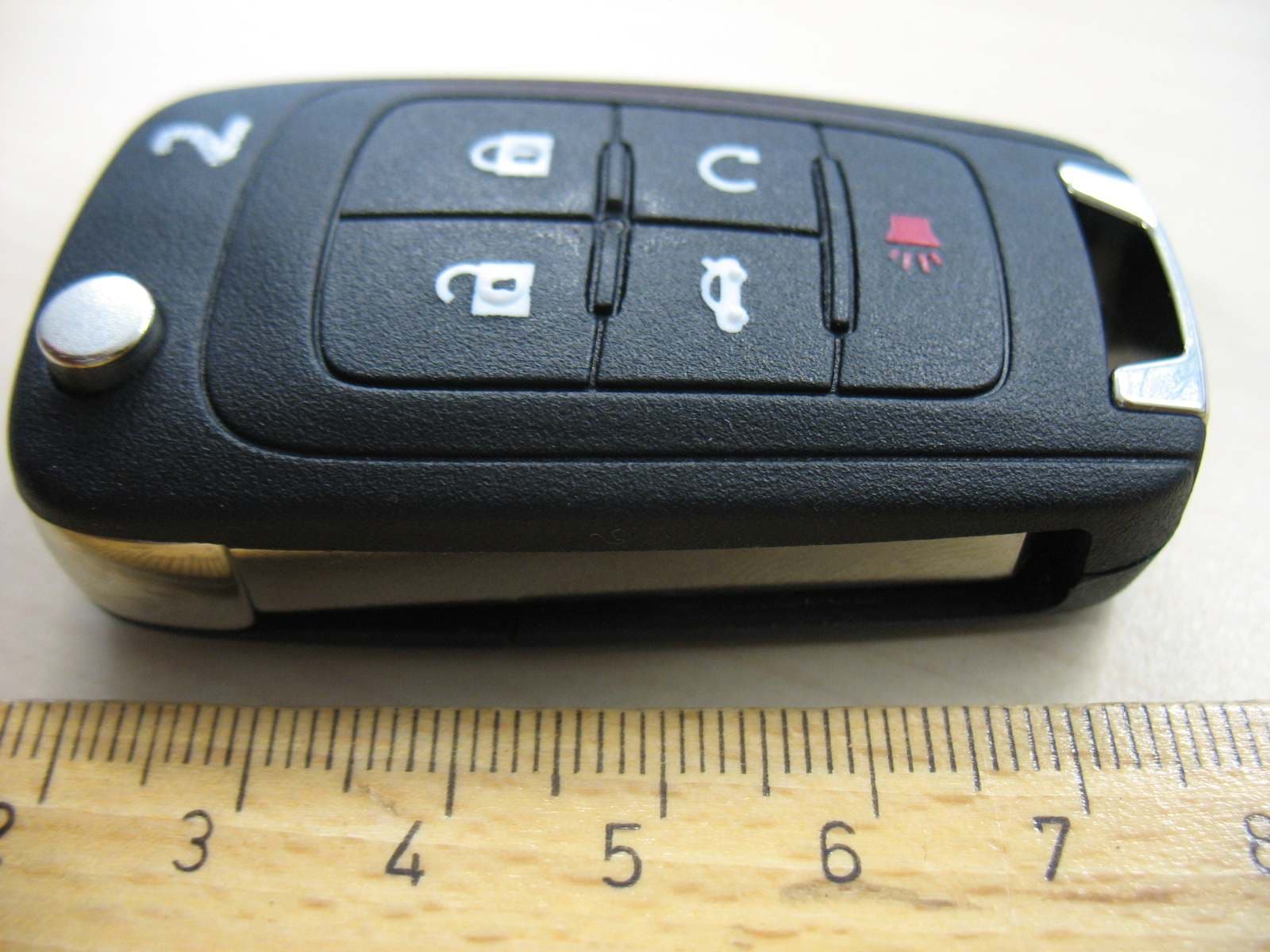
OHT01060512
Dec 13, 2009Keyless Entry
Equipment Class
DSC - Part 15 Security/Remote Control Transmitter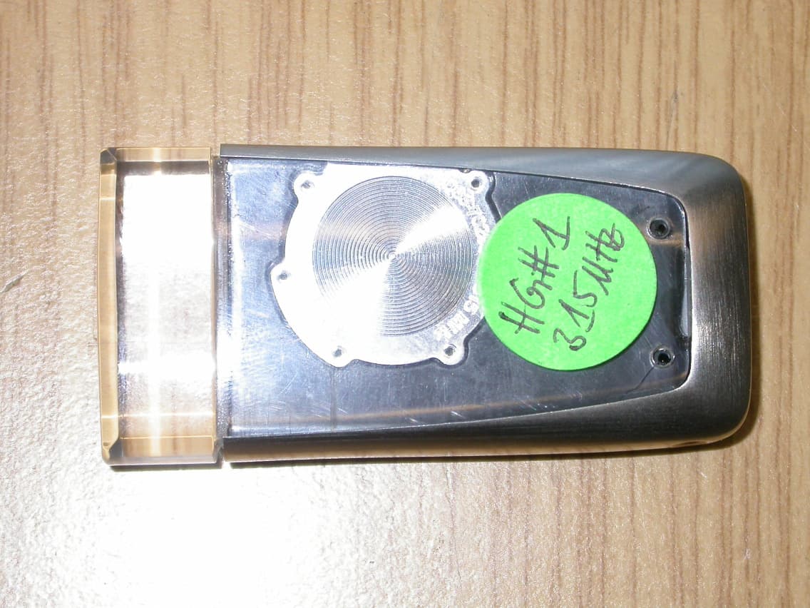
OHT7001550
Jan 15, 2008RKE Key Fob
Equipment Class
DSC - Part 15 Security/Remote Control Transmitter