OHTVACS598832
Strattec Security Corporation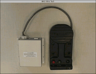
Click to zoom
Application Details
- Equipment Class
- DCD - Part 15 Low Power Transmitter Below 1705 kHz
- Date of Grant
- Jun 14, 1999
- Application Purpose
- Original Equipment
- Date of Application
- Mar 22, 1999
- Frequency Range
- 0.13400000 - 0.13400000
- Country
- United States
Documents & Files
Document Text
Text extracted from the exhibit documents filed with the FCC. Open a document above to read the original.
Users Manual
Revised 10/19/98 c:\ready_to_convert\doc\32511.doc VACS - Vehicle Access Control System • VACS is a combined vehicle control and security system which utilizes RFID technology. • This system allows a driver to enter and start a vehicle without a mechanical key while maintaining ahigh level of security. Unlocking the Vehicle * WAKING UP SYSTEM * If the vehicle is unused for greater than an hour then it is necessary to wake up the system using one of thefollowing methods: Hold the transponder in position for up to 5 seconds.Pressing an interior door release switch.Starting the engine. FROM OUTSIDE• Slowly pass the transponder in front of the Access Reader. This will unlock the door for 5 seconds. • For optimum performance hold transponder 3-6 inches from Access Reader FROM INSIDE• A transponder is not needed to open a door from the inside. • Press the interior door unlock switch. This will also unlock the door for 5 seconds. • The side and bulkhead doors may be unlocked manually by pushing the tab on the locking mechanismand pulling the door at the same time. • The rear rollup door may be unlocked manually by pushing the tab which is located on the bottom ofthe locking mechanism while unlatching and pulling the the door up. Note: The system may be operated a maximum of 3 times per minute. If a fourth attempt is made,the Access Reader will flash a RED LED and not operate. EMERGENCY ENTRANCE• In the event of a dead battery, the vehicle may be entered with a key via the rear rollup door INTERIOR LIGHTS• The interior lights will be activated when:(1) a transponder is read by one of the Access Readers (2) one of the doors is opened (3) the ignition is shut off • If no doors are opened after the interior lights are activated, the lights will extinguish after 10 seconds. • If a door is opened, the lights will extinguish 10 seconds after the door is closed. • If a door is left open, the interior lights will extinguish after 5 minutes. Starting & Stopping Vehicle• Vehicle will not respond unless it reads a programmed transponder • Make sure all doors are closed tight. While pressing the GREEN START SWITCH , a flashing RED LED on the Ignition reader indicates that a door is ajar. • For optimum performance hold transponder 2-6 inches from Ignition Reader ACTIVATING ACCESSORIES• Place hand above the ignition control reader and press the GREEN START SWITCH for less than 1/2 second. This will activate the accessories STARTING ENGINE• Place hand above ignition control reader and press the GREEN START SWITCH for more than 1/2 seconds Note: You have 10 seconds after the start switch is released to try and restart the vehicle. If this time has expired, the red stop switch has to be pressed, and then the green start switch has to bepressed again to start the engine. STOPPING ENGINE• No transponder is needed to shut off the accessories or the engine. • Press RED STOP SWITCH for more than 1/4 seconds. Engine will stop and interior lights will activate for 10 seconds. Security ModesThere are three security modes:Door Opened The security system will be armed 10 seconds after a door is opened.Alarm is triggered via motion sensors.All doors must be closed to start vehicle. Door Closed An exterior door must first be opened. The security system will then be armed 10seconds after all exterior doors are closed.Alarm is triggered via motion sensors and door sensors.All doors must be closed to start vehicle. Maintenance The security system will not activate.The vehicle may be started with open doors. Changing Security Mode• Place ignition in either Accessories ON or Engine Run mode. • Using either a wrist band transponder or Master Fob , press the BLACK ALARM CONTROL SWITCH . • When using the Master Fob, modes will cycle between Door Open - Red LED illuminated Door Closed - Yellow LED illuminated Maintenance - NO LED illuminated • When using a wrist band, modes will cycle between Door Open - Red LED illuminated Door Closed - Yellow LED illuminated Note: Maintenance mode cannot be entered with a wrist band. • Starting the engine with a Master Fob will automatically place the vehicle in maintenance mode. Disarming/Deactivation of Alarm• The Alarm can be deactivated by any of the following methods:(1) A valid transponder code is read by a Access Reader. (2) Starting the vehicle with a valid transponder or master code. (3) Placing the vehicle in “programming” mode via the ignition switch module. If the alarm is disarmed/deactivated and the vehicle is not started, the system will armitself after 10 seconds! Revised 10/19/98 c:\ready_to_convert\doc\32511.doc VACS - Transponder Programming • Programming can be conducted at any of the readers on the vehicle. Allsystem modules will receive the new codes via a communications bus. • The system can hold up to 10 unique codes. • All Access Readers which are not the source of programming will be inactive while in programming mode. This state is indicated by constant illuminationof the red LED. • The system provides 3 programming functions.(1) Add new transponder codes to an existing bank of codes in memory (10 maximum) (2) Delete current transponder codes in memory and add new codes (3) Change Master Code and delete current transponder codes in memory Programming via Access ReaderAdd new transponder codes to an existing bank of codes in memory • Slowly pass the Master Fob by the Access Reader and observe that the red LED in the Access Reader will flash once. This indicates that the system is in the add mode of operation. • Slowly pass an unprogrammed transponder by the Access Reader and observe that the red LED willquickly flash twice. This indicates that the transponder has been added to the systems’ memory. • You may continue to add codes to the systems’ memory by simply passing unprogrammed transponders by the Access Reader. • There are three methods of exiting this mode of operation.(1) Pass a programmed transponder by the reader (for example, the transponder that was just added)…
Text truncated - open the document above for the full version.
Attestation Statements
STRATTEC SECURITY CORPORATION / 3333 West Good Hope Road, Milwaukee, WI 53209 / 414.247.3333 / Fax 414.247.3329 March 10, 1999Time: 10:00 a.m. To:FCC Authorization & Evaluation Division 7435 Oakland Mills Road Columbia, MD 21045-0429 From: Michael FeuchtPhone: (414) 247-3364 Project EngineerFax: (414) 247-3329 Applicant: Strattec Security CorporationE-Mail: [email protected] Dear Ladies and/or Gentlemen: I appoint Kenneth L. Boston and James Blaha at L.S. Compliance, Inc., to act as an agent in the preparation under Part 15 of the rules and regulations of the Federal Communications Commission. I certify that the exhibitions properly describe the device being submitted under this application and will implement any changes described in the test report. The labels described will be affixed to each item. The following statement is required by the Federal Communications Commission: By checking Yes, the applicant certifies that, in the case of an individual applicant, he or she is not subject to a denial of federal benefits, that included FCC benefits, pursuant to section 5301 of the Anti-Drug Abuse Act of 1998, 21 U.S.C 853 (a), or, in the case of a non-individual applicant (e.g. corporation, partnership, or other unincorporated association), no party to the application is subject to a denial of federal benefits, that includes FCC benefits, pursuant to that section. XYesNo Dated this 10th day of March, 1999 By:Michael Feucht Title:Project Engineer / Strattec Security Corporation Phone:(414) 247-3364
Attestation Statements
STRATTEC SECURITY CORPORATION / 3333 West Good Hope Road, Milwaukee, WI 53209 / 414.247.3333 / Fax 414.247.3329 March 10, 1999Time: 10:00 a.m. To:FCC Authorization & Evaluation Division 7435 Oakland Mills Road Columbia, MD 21045-0429 From: Michael FeuchtPhone: (414) 247-3364 Project EngineerFax: (414) 247-3329 Applicant: Strattec Security CorporationE-Mail: [email protected] Dear Ladies and/or Gentlemen: I appoint Kenneth L. Boston and James Blaha at L.S. Compliance, Inc., to act as an agent in the preparation under Part 15 of the rules and regulations of the Federal Communications Commission. I certify that the exhibitions properly describe the device being submitted under this application and will implement any changes described in the test report. The labels described will be affixed to each item. The following statement is required by the Federal Communications Commission: By checking Yes, the applicant certifies that, in the case of an individual applicant, he or she is not subject to a denial of federal benefits, that included FCC benefits, pursuant to section 5301 of the Anti-Drug Abuse Act of 1998, 21 U.S.C 853 (a), or, in the case of a non-individual applicant (e.g. corporation, partnership, or other unincorporated association), no party to the application is subject to a denial of federal benefits, that includes FCC benefits, pursuant to that section. XYesNo Dated this 10th day of March, 1999 By:Michael Feucht Title:Project Engineer / Strattec Security Corporation Phone:(414) 247-3364
Block Diagram
VEHICLE ACCESS CONTROL SYSTEM March 13, 1999 IGNITION CONTROL MODULE BLOCK DIAGRAM DOOR OPENED ALARM CONTROL MODE INDICATORDOOR CLOSED ALARM CONTROL MODE INDICATOR TRUCK NOT USEDHORNINTERIOR LIGHTSSTARTIGNITIONACCESSORIES MOTION DETECTOR #2MOTION DETECTOR #1ALARM CONTROL MODEACCESSORIES / STARTSTOP IGNITION READER TRUCK BULK HEAD DOOREXTERIOR DOOR MICRO CONTROLLER SERIAL BUS CONTROLLER EEPROM MEMORY RF LIMITER RF SWITCH TUNING ANTENNA TI RFM MODULE AMPLIFIER FSK DEMOD LOGIC CNTL TX HARDWARE VOLTAGEREGULATOR AUXILIARY VOLTAGE FIRMWARE SERIAL BUS TO ACCESS MODULES YELLOW RED
External Photos
Strattec - Ignition Control Module and Ignition Reader
External Photos
Strattec - Ignition System ... Flip Side
External Photos
Strattec - FCC ID Label attached to Ignition Module
External Photos
Strattec - Close up of Ignition Reader
External Photos
Strattec - Ignition Reader, Interconnect wiring
External Photos
Strattec - Ignition Reader Antenna Coil
External Photos
Strattec - Close up of Ignition Reader
Internal Photos
Strattec - PCB up close, Component Side
Internal Photos
Strattec - PCB Foil Side
Operational Description
VEHICLE ACCESS CONTROL SYSTEM - IGNITION SYSTEM THEORY OF OPERATION E XECUTIVE S UMMARY The Vehicle Access Control System (VACS) is an RFID based keyless entry, ignition, and security system designed for package delivery vehicles. This document outlines the operation and theory of the ignition portion of VACS called the ignition system. Following is a summary of the Ignition system topology. Table 1 - Ignition System Technical Summary Technology Basis: Texas Instruments TIRIS RFID System Transponder: TIRIS RI-TRP-R9QL Disk Type FSK Transmission: 134.2 kHz mark, 122.2 kHz Space 8.7 kbit/s, 101 dBμA/m at 5 cm (max) Receiver Components: RI45538 RFID Receiver IC: 17.1776 Mhz Crystal Oscillator Charging Transmitter: 134.2 kHz, 0.50 Duty Cycle 130 dBμA/m at 5 cm Antenna System: Loop Antenna, 65 μH, Circuit Q ≅ 21 Electronic Control: Motorola 68HC705C8A ,4.000 Mhz Crystal Oscillator Harris CDP68HC68S1 Wire-Line Serial Bus Power Source: 12 Volt Automotive Battery F UNCTIONAL D ESCRIPTION The purpose of the ignition system is to read transponder codes and activate the vehicle accessories and/or start the engine when the appropriate codes are read. The ignition system is comprised of four major components: 1) Texas Instruments transponder 2) The ignition reader, 3) the ignition control module and 4) an assorted vehicle relays (DC). The transponder is the passkey to the system, worn on the driver’s wrist, the ignition reader contains a wire loop antenna, and the ignition control module contains the TIRIS receiver and microcontroller circuitry. To activate the vehicle accessories, the driver places his wristband transponder approximately 10 cm from the dash-mounted ignition reader and depresses the ACC/START push-button. The Ignition System Theory of OperationMarch 4, 1999 Page 2 ignition control module / loop antenna charge the transponder and the transponder transmits a 64 bit key code back to the ignition control module though the same antenna. If the transponder code matches one of the ten key codes stored in ignition control module memory, the ignition control module energizes the accessories relay. Holding-in the ACC/START relay an additional 0.5 second energizes the engine start relay, and cranks the engine. The ignition system also incorporates an automotive serial bus used to share key codes with access modules controlling vehicle doors, if so installed. Following is a technical description of the ignition system topology. T ECHNICAL D ESCRIPTION All electronic circuitry resides on one double-sided through hole circuit board, with the exception of the loop antenna and DC control relays. Details of TIRIS communications are outlined below. TIRIS Communications Transponder Charging The primary function of the ignition system is to read transponder codes. This is accomplished through the use of the Texas Instruments RI45538 TIRIS receiver IC. The device performs TIRIS transponder charging, data demodulation and synchronization functions as directed by the Motorola MC68HC705C8A microcontroller. A TIRIS read operation involves charging the transponder, then detecting and demodulating the FSK transmission. When directed to charge a transponder, the RI45538 generates two 134.2 kHz logic signals used to gate a push-pull MOSFET power stage. The power stage drives a series resonant circuit consisting of a tuning capacitor and the loop antenna, located in the ignition reader. A transmission circuit Q of approximately 21 generates an antenna voltage and magnetic field of roughly 50 Volts and 130 dBμA / m at 6 cm respectively. Charging duration is roughly 50 ms. During the charge cycle, voltage induced across the transponder’s loop antenna is rectified and used to charge a power capacitor. Capacitor energy powers the transponder transmitter which is activated after the charge burst has terminated. Data Reception After the transponder has detected the end of the charge burst, it transmits 128 bits of keycode and header information using FSK modulation. Typical space / mark frequencies are 132.4 kHz / 123.2 kHz respectively at a maximum transmission rate of 8.7 kbit/s. Each bit duration is 16 RF cycles yielding a space duration of 119 μs and a mark duration of 130 μs. The maximum Ignition System Theory of OperationMarch 4, 1999 Page 3 transmission time for 128 bits is 20 ms. Maximum transponder output field strength at 5 cm is 101 dBμA/m. The FSK information is detected by the VACS TIRIS receiver using the same hardware used to generate the charge burst. In receive mode, the antenna circuit is tuned for a slightly lower Q to accommodate the wider FSK bandwidth signal generated by the transponder. The microcontroller disables the RI45538 transmitter to terminate the charge burst, and after a waiting time, the RI45538 decodes the FSK data. Clock information is derived from the FSK signal and the RI45538 generates data bits which are processed by the microcontroller. The ignition system transmits a charge burst every 125 ms while the ACC/START push-button is depressed. Bursts are not transmitted if the push-button is not depressed. Microcontroller Operations The ignition system utilizes the Motorola MC68HC705CA to coordinate the TIRIS receiver, control code management, and activate the accessories / engine relays upon valid code reception. A valid code is one which has been previously programmed into the ignition system’s National Semiconductor NM93C46 EEPROM. Ten keycodes (maximum) and one master code may be stored in memory. The processor interrogates each transponder and compares its code with contents of the EEPROM. When a match is found, the processor activates a digital output which energizes the appropriate accessories / start relay. When a master transponder code is read, the processor places the system in program mode, allowing manipulation of the EEPROM memory. Three programming operations are allowed: a single keycode may be added, all keycodes may be deleted or a new master code may be reprogramme…
Text truncated - open the document above for the full version.
Schematics
- VACS IGNITION MODULE STRATTEC SECURITY CORP. C 11 Friday, July 10, 1998 598831AC5 TitleSize Document Number Rev Date: Sheet of 12V 12V12V 12V_F 12V12V 12V12V12V12V12V12V12V 12V 5V_RF 5V_AUX 5V_RF 5V_RF 5V 5V 5V 5V_AUX 5V_AUX 5V_RF 5V_AUX 5V VDD VSS 12V_F 12V_F GND 5V 5V 5V 5V VCC 5V 5V 5V 5V 12V PPPPPPP P PP D P PP RF P CONNECT RFGND AND DGNDTO PGND AT C33/C35 PP P PPPPP D D D D D D D D D D RF RF RF RF RF RF RF RF RF P P EECLR RXDTTXCTRXCKBUSCSMOSIBUSIDLEAUXPWREECSMISOLGHTHRNSTARTIGNACCESSINTLGHTSBUSWKUPLED1LED2SCKBUSCNTL WDT PAGERBUSCLK RV1V24ZA50 D33 SA20A U6RI-RFM-006A-00 A3OP 1 A3IN 2 A2OP 3 A2IN 4 A1OP 5 A1IN 6 TXLO 7 TXHI 8 OSCI 9 OSCO 10 GND 11 VCC 12 TPC 13 TXCT* 14 RXDT 15 RXCK 16 Q13RFD14N05L 1 23 Q12RFD10P03L 1 23 Q8RFD10P03L 1 2 3 R151001/4W R14 620 1/2W R17 620 1/2W R181001/4W R21 620 1/2W R231001/4WR271001/4W R24 620 1/2W R321001/4W R37 620 1/2W R391001/4W R30 620 1/2W R621M R631M R64470K R5615K R611M R6010K R5910K R5810K R5710K R65101/2W R28100 R29100 R3510K R4322K R3613K R40240 R252.2K R162.2KR192.2KR222.2KR262.2KR312.2K R3410R3810 R4810KR5510K R546201/2W R4911/4W R1310K R1010K R910K R810K R710K R610K R510K R410K R310K R672201/4W R204.7M R511K R661K R466201/2W R33470 R5033K R47150K R4113K R442.2K R68150K R451001/4W R42 620 1/2W R110K R210K Q5 2N3906 Q112N3904 Q7 2N3904 Q92N4401 Q22N4401Q32N4401Q42N4401 Q102N4401 Q62N4401Q12N4401 U2NM93C46 NC 7 VCC 8 DO 4 DI 3 SK 2 CS 1 GND 5 NC 6 U3MC33164 IN 2 RSET 1 GND 3 U7LP2954AIT IN 1 GND 2 OUT 3 D24HLMP-1301 D21N4148D51N4148D81N4148D111N4148D171N4148D141N4148D211N4148 D29 1N4148 D301N4004 D201N4148 D41N4004D71N4004D10 1N4004 D131N4004 D251N4148 D11N4004 D321N4148 D281N4148 D34 1N4148 D36 1N4148 D38 1N4148 D37 1N4148 D35 1N4148 D231N4148 D311N4148 Y2 17.1776MHz Y1 4MHz J1-1 BUS_LO 1 J1-5 BUS_HI 5 J1-7 ACCESS 7 J1-3 IGN 3 J1-6 START 6 J3-2 INTLGHTS 2 J3-5 LGHTHRN 5 J1-8VBATT 8 J1-2 12V 2 J3-1 12V 1 J3-8MD1 8 J3-4MD2 4 J3-7 EXTDOOR 7 J1-4GND 4 J3-3 BLKDOOR 3 J2-9IGON 9 J2-4IGKILL 4 J2-8 MODESW 8 J2-10 ANT_HI 10 J2-5 ANT_LO 5 J2-2 LED1 2 J2-1 LED2 1 J2-7 12V_F 7 J2-3GND 3 J2-6 12V_F 6 U4CDP68HC68S1 CLK 1 VDD 14 A 2 MODE 4 B 3 BUS- 6 BUS+ 5 VSS 7 XMIT 8 REC 9 SCK 10 CS* 11 IDLE* 12 CNTL 13 C2210uF16V + C2310uF16V + C33220uF35V + C347uF10V + C212200uF10V + C10.1uFC20.1uFC40.1uFC90.1uFC160.1uFC110.1uFC170.1uF C31 330 pF C30 0.001uF C29 0.001uF C28 0.001uF C25 0.1uF C390.1uF C3633pF C3733pF C2733pF C32 330 pF C38 0.022uF400V C70.1uF C150.1uF C200.047uF C533pF C633pF C340.1uF C350.1uF C260.1uFC190.1uFC120.1uFC130.1uF C140.47uF C80.1uF C180.1uF U5C74HC132 9 10 8 U5A74HC132 12 3 U5B74HC132 45 6 U5D74HC132 1213 11 U168HC705C8A OSC1 43 OSC2 42 RESET 1 IRQ 2 PD0 32 PD5 37 PD7 39 TCAP 41 PA0 12 PA1 11 PA2 10 PA3 9 PA4 8 PA5 7 PA6 6 PA7 5 PB0 13 PB1 14 PB2 15 PB3 16 PB4 17 PB5 19 PB6 20 PB7 21 PC0 31 PC1 30 PC2 29 PC3 28 PC4 27 PC5 26 PC6 25 PC7 24 PD1 33 PD4 36 PD2 34 PD3 35 TCMP 38 VPP 4 D31N5245BD91N5245BD151N5245BD191N5245BD61N5245BD121N5245B D161N5245BD181N5245B D221N5245B R532.2K Q142N4401 D271N4004 D26 1N4148 J3-6 PAGER 6 S1SW DIP-2 12 43 R12100 R523.3K1/2W
Test Report
L. S. COMPLIANCE, Inc. FCC ID: OHTVACS598832 LSC-Strttec ignition-90053 Page 0 of 28 COMPLIANCE TESTING OF THE IGNITION CONTROL SYSTEM - T EST R EPORT - Project Number: 90053 Prepared for: Michael Feucht Strattec Security Systems 3333 W. Good Hope Rd. Glendale, WI 53209-2043 Date(s) tests were performed: March 23 rd , 1999 L. S. COMPLIANCE, Inc. FCC ID: OHTVACS598832 LSC-Strttec ignition-90053 Page 1 of 28 All results of this report relate only to the items that were tested. This report is not to be reproduced, except in full, without written approval of L.S.Compliance, Inc. L. S. COMPLIANCE, Inc. FCC ID: OHTVACS598832 LSC-Strttec ignition-90053 Page 2 of 28 Table of Contents: SectionDescriptionPage # Index1 1.1 Description of Measurement Facilities2 1.2Signature Page3 1.3Summary of Test Report4 1.4Introduction5 1.5Purpose5 1.6Radiated Emission Test Setup5 1.7Radiated Emission Test Procedure6 1.8Test Equipment Utilized for Radiated Emission7 1.9Restricted Bands (Frequencies and Limits)8 1.10Photos taken during testing9 1.11Summary of Results and Conclusions12 1.12Test Equipment List13 AppendicesASample Calculations:14 i.Calculation of Radiated Emissions Limits15 ii.Resultant Limits16 BData Charts17 CGraphs21 L. S. COMPLIANCE, Inc. FCC ID: OHTVACS598832 LSC-Strttec ignition-90053 Page 3 of 28 1.1 D ESCRIPTION OF M EASUREMENT F ACILITIES Site on File with the FCC ID Number: 31040/SIT 1300F2 “ The site referenced above has been found to comply with the test site criteria found in ANSI C63.4-1992 and Title 47CFR, FCC Part 15 Section 2.948.” L. S. COMPLIANCE, Inc. FCC ID: OHTVACS598832 LSC-Strttec ignition-90053 Page 4 of 28 1.2 SIGNATURE PAGE Prepared By: 28 April 1999 Date Approved By: 28 April 1999 Kenneth L. Boston, EMC Lab Manager Date PE #31926 Registered Professional Engineer (State of Wisconsin) L. S. COMPLIANCE, Inc. FCC ID: OHTVACS598832 LSC-Strttec ignition-90053 Page 5 of 28 1.3 S UMMARY OF T EST R EPORT MANUFACTURER:Strattec Security Systems MODEL:Ignition Control Module SERIAL:N/A DESCRIPTION:Vehicle Access Control System: Ignition Control System The Ignition Control System was found to “meet” the radiated emission specification of Title 47 CFR, FCC Part 15, subpart C, for an intentional radiator. No conducted emission tests were performed due to the product not being powered off of the public AC mains. The Ignition Control System was also found to “meet” the radiated emission specification of Title 47 CFR FCC Part 15, subpart B for emissions with regards to the class B digital sections of the product. This product is a composite device, with the digital section subject to verification. Therefore this technical report will primary contain data that is pertinent to the certification of the transmitter section of the product. L. S. COMPLIANCE, Inc. FCC ID: OHTVACS598832 LSC-Strttec ignition-90053 Page 6 of 28 1.4 I NTRODUCTION On March 23 rd of 1999, a series of Radiated Emissions tests were performed on a sample model of the Ignition Control System. This is a transceiver, which is designed to read transponder codes and activate the vehicle accessories and/or start the engine when the appropriate codes are read. The ignition system is comprised of four major components: 1)a Texas Instruments transponder, 2) the ignition reader 3) the ignition control module and 4) assorted vehicle relays (DC). To activate the vehicle accessories, the driver places his wristband transponder approximately 10 cm from the dash-mounted ignition reader and depresses the ACC/START push-button. The ignition control module then charges the transponder with a short burst, whereupon the transponder transmits a 128 bit key code back to the ignition control module though the same antenna. If the transponder code matches one of the ten key codes stored in the ignition control module memory, the ignition control module energizes the appropriate relay. These tests were performed using the test procedures outlined in ANSI C63.4-1992 for intentional radiators, and in accordance with the general limits set forth in FCC Part 15.209 for a low power transmitter. Tests were also performed as outlined in ANSI C63.4-1992 for non-intentional radiators, in order to allow verification of emissions from the digital section of the product. These tests were performed by Thomas T. Lee, of L. S. Compliance, Inc. and witnessed by Jerome Alberte of Strattec Security Systems. 1.5 P URPOSE The above mentioned tests were performed in order to determine the compliance of the product with limits contained in various provisions of Title 47 CFR, FCC Part 15, including: 15.10915.209 15.205 All radiated emissions tests were performed to measure the emissions in the frequency bands described by the above sections, and to determine whether said emissions are below the limits established by the above sections. These tests were performed in accordance with the procedure described in the American National Standard for methods of measurement of Radio-Noise Emissions from Low-Voltage Electrical and Electronic Equipment in the Range of 9 kHz to 40 GHz (ANSI C63.4-1992). Another document used as reference for the EMI receiver specification was the International Special Committee on Radio Interference (CISPR) number 16-1 (1993). 1.6 R ADIATED E MISSIONS T EST S ETUP The test sample was operated within the 3 meter Semi-Anechoic, FCC listed chamber located at L.S. Compliance in Cedarburg, WI. and also on the 10 meter Open Air Test Site located outside the L.S. Compliance facility. The test sample was operated with power supplied by an external DC rechargeable battery. The test sample was positioned upon an 80 cm high wooden table, which was positioned upon the 2 meter turntable within the chamber. The measurement antenna, mounted upon a motorized mast was then placed 3 meters from the product perimeter. L. S. COMPLIANCE, Inc. FCC ID: OHTVACS598832 LSC-Strttec ignition-90053 Page 7 of 28 This allowed the reader to be scanned in both azimuth and elevatio…
Text truncated - open the document above for the full version.
Contact Information
Applicant
Richard Messina(Vice President Global Engineering and Purchasing)
Technical Contact
StrattecMichael G Feucht
[email protected]414-247-3364
3333 West Good Hope Road · Milwaukee, Wisconsin · United States
Non-Technical Contact
L. S. Compliance, Inc.Jim Blaha
[email protected]414-375-4400
Test Firm
L. S. Compliance, Inc.James Blaha
262-375-4400Fax: 262-375-4248
Technical Specifications
| # | Rule Parts | Frequency Range | Power Output |
|---|---|---|---|
| 1 | 15C | 0.134 MHz - 0.134 MHz | - |
Other Applications from Strattec Security Corporation
OHT3731687
Apr 04, 2023RKE Transmitter
Equipment Class
DSC - Part 15 Security/Remote Control Transmitter
OHT3731568
Feb 03, 2020LF Transmitter
Equipment Class
DSC - Part 15 Security/Remote Control Transmitter
OHT05918179
Feb 28, 2013Flap Key Fob
Equipment Class
DXX - Part 15 Low Power Communication Device Transmitter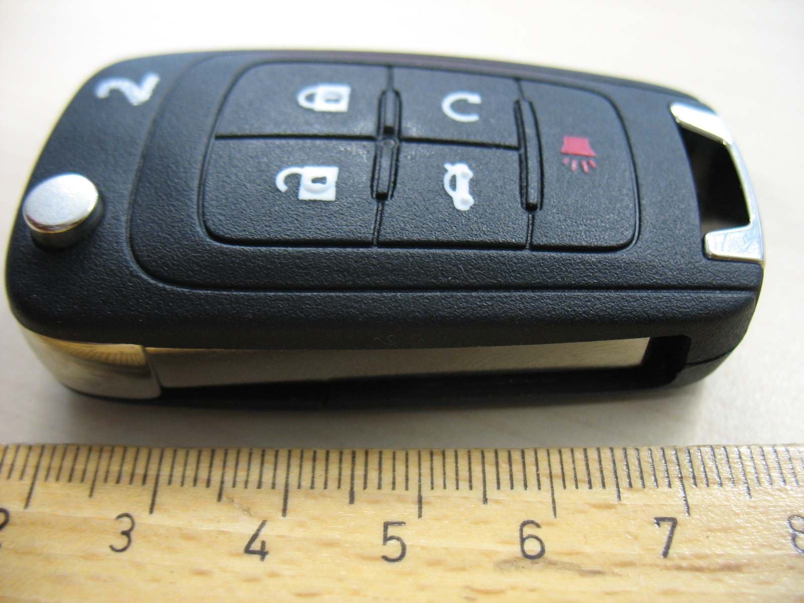
OHT01060512
Dec 13, 2009Keyless Entry
Equipment Class
DSC - Part 15 Security/Remote Control Transmitter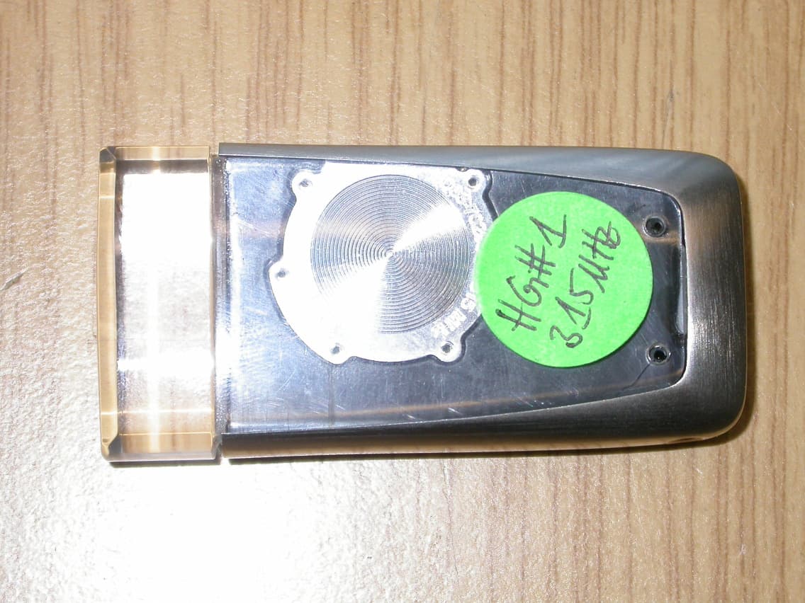
OHT7001550
Jan 15, 2008RKE Key Fob
Equipment Class
DSC - Part 15 Security/Remote Control Transmitter