OJM-OTX-XXX-KFMSAKeyfob Transmitter
Linx Technologies
Click to zoom
Application Details
- Equipment Class
- DSC - Part 15 Security/Remote Control Transmitter
- Date of Grant
- Aug 30, 2005
- Application Purpose
- Original Equipment
- Date of Application
- Aug 30, 2005
- Equipment Note
- Keyfob Transmitter
- Frequency Range
- 433.92000000 - 433.92000000
- Company
- Linx Technologies
- Country
- United States
Documents & Files
Document Text
Text extracted from the exhibit documents filed with the FCC. Open a document above to read the original.
Users Manual
DESCRIPTIONThe Linx MS Series Keyfob transmitter isideal for remote control and command appli-cations. Available in 315, 418, or 433.92MHzversions, it has been pre-certified for FCCPart 15, Industry Canada, and European CE(433MHz version only) compliance. Thisdramatically reduces development cost andtime to market. The high-performancesynthesized design provides superiorfrequency accuracy and minimizes bodyproximity effects. When combined with an LRreceiver, the keyfob can operate at distancesof up to 1,000ft. Ease of use and security aredramatically enhanced by the on-board MSSeries encoder, which allows instant creationof 16,000,000 unique addresses withoutcumbersome DIP switches or cut-traces.When paired with a MS Series decoder,keyfob identity can be determined and buttonpermissions established. The keyfob isavailable in 1 to 5 button configurations andcan be custom labeled. FEATURES FCC, Canada, and CE Pre-Certified Utilizes the advanced MS encoder Long range Simple user setup 2 24 unique addresses 1 to 5 buttons Compact, stylish package APPLICATIONS INCLUDE General Remote Control Keyless Entry Garage / Gate Openers Call Systems Home / Industrial Automation Wire Elimination OEM ConfigurationsWith a one-time NRE and minimumorder, Linx can configure the keypadand label areas to meet your specificrequirements. Contact Linx for details. MS KEYFOB TRANSMITTER DATA GUIDE 2.23" 1.00" 0.45" 1.37" S4S2 S1 S3 S5 Revised 6/30/05 PART # DESCRIPTION OTX-***-HH-KF#-MS-xxx MS Keyfob TransmitterEVAL-***-HH-KF#-MS MS Keyfob Development System # = Number of Buttons, 1 to 5*** = 315, 418 (Standard), 433.92MHzxxx = Color Leave blank for standard BlackWHT = White CGY= Gray CBL = Blue CRE = Red CPU = Purple ORDERING INFORMATION Figure 1: Physical Dimensions WIRELESS MADE SIMPLE Page 3 Page 2 THEORY OF OPERATION The MS Series Keyfob Transmitter combines a high-performance synthesizedtransmitter with an on-board MS Series encoder IC to form a highly reliable, yetcost-effective RF remote control transmitter. The transmitter’s synthesized architecture delivers superior stability and frequency accuracy while minimizingthe effects of temperature and body proximity.The advanced MS Series encoder has several advantages over previoussolutions. It provides more security by offering 2 24 addresses, which is several orders of magnitude greater than older encoders. Furthermore, the address isinstantly established with a simple button press, eliminating cumbersome DIPswitches and cut traces. When paired with a MS Series decoder, keyfob identitycan be determined and distinct transmitter-receiver relationships established.The keyfob operates in the following manner: when a button is pressed on thekeyfob, power is applied to the internal circuitry and the encoder IC is enabled.The encoder then detects the logic states of the button data lines. The encoderdata is used to modulate the transmitter, which, through the antenna, conveysthe data into free space. The transmission cycle continues until the button isreleased. On the receiver side, a MS Series decoder IC is used to check thetransmitter’s address bits against the address saved in memory. If a match isconfirmed, and if the decoder has permission to recognize the specific buttonbeing pressed, the decoder’s outputs are set to replicate the transmitter’s buttonstates. These outputs can then be used to activate external circuitry required bythe application.The transmitter is compatible with the LC and LR product families. Forapplications where range is critical, the LR Series receiver is the best choice dueto its outstanding sensitivity. When the keyfob transmitter is combined with an LRSeries receiver and the MS Series decoder chip, ranges up to 1,000 feet arepossible. Appl ications operating over shorter distances will also benefit from the increased link reliability and superior noise immunity provided by the LR receiver. SETTING THE TRANSMITTER ADDRESS The encoder address is set by using apaper clip to press theCREATE_ADDR button on the boardthrough the hole in the back of thecase. When the button is depressed,an LED on the board will light upindicating that the address is beingcreated. The address will berandomized for as long as the button isheld down. When the button isreleased, the address is stored inmemory and the LED will begin flashingto indicate that the Control Permissions may now be set. Press the buttons thatthe transmitter will have the authority to access. Press the CREATE_ADDRbutton with the paper clip again or wait 17 seconds for it to time out and theaddress is set. The decoder will need to learn the address before it will acceptany transmissions. Please see the Typical Applications section of this data guideor the MS Series Decoder Data Guide for details on learning an address. BUTTON ASSIGNMENTS The keyfob is available in five unique button configurations. Those configurationsand the corresponding switch numbers are shown in the figure below. The tableshows which encoder data line has been assigned to each switch. When abutton is pressed, the data line will go high, causing the corresponding data lineon the decoder to go high if the addresses match. S4S2 S1 S3 S5 S5 S2S5S4 S4 S2 S4 S1 S3 S2 Figure 3: OTX-***-HH-KF#-MS Button Assignments Figure 2: CREATE_ADDR Button Access Button Data Line S1 D0 S2 D1 S3 D2 S4 D3 S5 D4 ELECTRICAL SPECIFICATIONS PP aa rr aa mm ee tt ee rr DD ee ss ii gg nn aa tt ii oo nn MM ii nn .. TT yy pp ii cc aa ll MM aa xx .. UU nn ii tt ss NN oo tt ee ss POWER SUPPLYOperating Voltage V CC 2.1 3.0 3.6 VDC – Supply Current I CC – 3.4 – mA – Power-down Current I PDN – 5.0 – nA 1 TRANSMITTER SECTIONTransmit Frequency Range F C OTX-315-HH-KF#-MS – 315 – MHz – OTX-418-HH-KF#-MS – 418 – MHz – OTX-433-HH-KF#-MS – 433.92 – MHz – Center Frequency Accuracy – -50 – +50 kHz – Data Rate – – 9600 – bps – ENVIRONMENTALOperating Temperature Range – -40 – +85 ° C1 1. Characterized, but not tested.Notes CREATE_ADDR Button…
Text truncated - open the document above for the full version.
Block Diagram
OTX-xxx-HH-KF#-MS Block Diagram
Cover Letter(s)
Scott McCutchan From: Scott McCutchan [[email protected]] Sent: Monday, August 22, 2005 12:38 AM To: '[email protected]' Cc: 'Mike' Subject: FCC ID: OJM-OTX-XXX-KFMSA 8/22/2005 Mr. Fujimoto: In order for processing of this application (FCC ID: OJM-OTX-XXX-KFMSA) to continue, the following issue(s) will have to be addressed: 1) Please upload a sample of the proposed FCC label and a photo or diagram showing its location on the device(s). 2) Please submit an external photo of the front of the 433 MHz unit 3) Please submit a letter from the applicant stating that the modifications listed in the test report will be made to all production units. The item(s) indicated above must be submitted before processing can continue on the above referenced application. Failure to provide the requested information within 60 days of the original e-mail date may result in application dismissal and forfeiture of the filing fee. Also, please note that partial responses increase processing time and should not be submitted. Please upload responses and/or exhibits to the electronic filing website. Your correspondence number is OJM-OTX-XXX-KFMSA-1. Best regards, Scott McCutchan Operations Manager Compatible Electronics TCB 19121 El Toro Road Silverado/Lake Forest, CA 92676 (949) 589-0700 Fax (949) 589-7700 [email protected]
Cover Letter(s)
Correspondence by Project Project Number: -1296371963 Correspondence Number Memo OJM-OTX-XXX-KFMSA-1 1) Please upload a sample of the proposed FCC label and a photo or diagram showing its location on the device(s). Response: The FCC ID label and Location has been uploaded. 2) Please submit an external photo of the front of the 433 MHz unit Response: The entire external photos for the 433 MHz version has been uploaded. The previous file was the wrong file uploaded. 3) Please submit a letter from the applicant stating that the modifications listed in the test report will be made to all production units. Response: The modification letter has been uploaded
ID Label/Location Info
575 SE ASHLEY PLACE ● GRANTS PASS, OR 97526 PHONE: (800) 736-6677 ● FAX: (541) 471-6251 The FCC and Industry Canada ID numbers for the Keyfob transmitter are: FCC ID: OJM-OTX-XXX-KFMSA IC: 5840A-KFMSXXXA The label and the location on the unit are shown below. The required disclaimers will be included in the User’s Manual. The label is applied to the back of the unit. This is shown below in actual size.
Operational Description
575 SE ASHLEY PLACE ● GRANTS PASS, OR 97526 PHONE: (800) 736-6677 ● FAX: (541) 471-6251 6/17/2005 Compatible Electronics, This document contains information for the OTX-xxx-HH-KF#-MS Keyfob transmitter that is required for you to complete testing and filing for FCC, Industry Canada, and CE certification. We are requesting certification on three frequencies for FCC and Industry Canada (315MHz, 418MHz, and 433.92MHz) and one frequency for CE (433.92MHz). A brief description of the unit and its operation follows: The OTX-xxx-HH-KF#-MS Keyfob transmitter combines a synthesized archetecture OOK transmitter with an on-board encoder IC to form a simple yet effective RF remote-control transmitter. When a button is pressed on the remote unit, power is applied to the internal circuitry and the encoder IC is enabled. The encoder then detects the logic states of the button data lines. These states are formatted into a 2-word transmission cycle that continues until the button is released. The encoder data is used to modulate the transmitter that, through the antenna, conveys the data into free space. Once data is received, a decoder IC is used to check the transmitter's address against an address saved in memory. If a match is confirmed, the decoder’s outputs are set to replicate the transmitter’s button states. These outputs can then be used to activate whatever external circuitry is required by the application. The transmitters may need a modification of a level adjust resistor (R1) to tune the output power to the maximum legal limit. A map of the board showing the resistor location, schematic, and graph of output power vs. resistor value are included in this document and a kit of various value resistors has been included in the box with the units to be tested. Please inform us of what value will give us the maximum legal output so that we may use that value in production. All of the transmitters are wired for continuous modulated transmission upon inserting the battery by shorting one of the buttons. This has been done to make your testing easier and is not done in production. The worst-case duty cycle is 50%. The battery holder is marked with a “+” on it to indicate polarity. Should you have any questions about the units, please do not hesitate to call Ammon Gomez ( [email protected]) or Justin Hopper ( [email protected]) at 1-800-736-6677 or (541)-471-6256.
Schematics
OTX-xxx-HH-KF#-MS Schematic
Test Report
Report Number: B50630D1 FCC Part 15 Subpart B and FCC Section 15.231 Test Report Keyfob Transmitter P/N: OTX-xxx-HH-KF#-MS 114 OLINDA DRIVE, BREA, CALIFORNIA 92823 PHONE: (714) 579-0500 FAX: (714) 579-1850 Page 1 of 16 FCC PART 15, SUBPART B and C TEST REPORT for KEYFOB TRANSMITTER P/N: OTX-xxx-HH-KF#-MS Prepared for LINX TECHNOLOGIES 575 S.E. ASHLEY PLACE GRANTS PASS, OREGON 97526 Prepared by:_____________________ KYLE FUJIMOTO Approved by:____________________ MICHAEL CHRISTENSEN COMPATIBLE ELECTRONICS INC. 114 OLINDA DRIVE BREA, CALIFORNIA 92823 (714) 579-0500 DATE: JULY 11, 2005 REPORT APPENDICES TOTAL BODY A B C D E PAGES 16 2 2 2 17 34 73 This report shall not be reproduced except in full, without the written approval of Compatible Electronics. Report Number: B50630D1 FCC Part 15 Subpart B and FCC Section 15.231 Test Report Keyfob Transmitter P/N: OTX-xxx-HH-KF#-MS 114 OLINDA DRIVE, BREA, CALIFORNIA 92823 PHONE: (714) 579-0500 FAX: (714) 579-1850 Page 2 of 16 TABLE OF CONTENTS Section / Title PAGE GENERAL REPORT SUMMARY 4 SUMMARY OF TEST RESULTS 4 1. PURPOSE 5 2. ADMINISTRATIVE DATA 6 2.1 Location of Testing 6 2.2 Traceability Statement 6 2.3 Cognizant Personnel 6 2.4 Date Test Sample was Received 6 2.5 Disposition of the Test Sample 6 2.6 Abbreviations and Acronyms 6 3. APPLICABLE DOCUMENTS 7 4. DESCRIPTION OF TEST CONFIGURATION 8 4.1 Description of Test Configuration - EMI 8 4.1.1 Cable Construction and Termination 9 5. LISTS OF EUT, ACCESSORIES AND TEST EQUIPMENT 10 5.1 EUT and Accessory List 10 5.2 EMI Test Equipment 11 6. TEST SITE DESCRIPTION 12 6.1 Test Facility Description 12 6.2 EUT Mounting, Bonding and Grounding 12 7. TEST PROCEDURES 13 7.1 Radiated Emissions (Spurious and Harmonics) Test 13 7.2 Radiated Emissions (Spurious and Harmonics) Test (continued) 14 7.3 Bandwidth of the Fundamental 15 8. CONCLUSIONS 16 Report Number: B50630D1 FCC Part 15 Subpart B and FCC Section 15.231 Test Report Keyfob Transmitter P/N: OTX-xxx-HH-KF#-MS 114 OLINDA DRIVE, BREA, CALIFORNIA 92823 PHONE: (714) 579-0500 FAX: (714) 579-1850 Page 3 of 16 LIST OF APPENDICES APPENDIX TITLE A Laboratory Recognitions B Modifications to the EUT C Additional Models Covered Under This Report D Diagrams, Charts, and Photos • Test Setup Diagrams • Radiated Emissions Photos • Antenna and Effective Gain Factors E Data Sheets LIST OF FIGURES FIGURE TITLE 1 Plot Map And Layout of Radiated Test Site Report Number: B50630D1 FCC Part 15 Subpart B and FCC Section 15.231 Test Report Keyfob Transmitter P/N: OTX-xxx-HH-KF#-MS 114 OLINDA DRIVE, BREA, CALIFORNIA 92823 PHONE: (714) 579-0500 FAX: (714) 579-1850 Page 4 of 16 GENERAL REPORT SUMMARY This electromagnetic emission test report is generated by Compatible Electronics Inc., which is an independent testing and consulting firm. The test report is based on testing performed by Compatible Electronics personnel according to the measurement procedures described in the test specifications given below and in the "Test Procedures" section of this report. The measurement data and conclusions appearing herein relate only to the sample tested and this report may not be reproduced without the written permission of Compatible Electronics, unless done so in full. This report must not be used to claim product endorsement by NVLAP, NIST or any other agency of the U.S. Government. Device Tested: Keyfob Transmitter P/N: OTX-xxx-HH-KF#-MS S/N: N/A Product Description: See Expository Statement. Modifications: The EUT was modified during the testing. Please see the list located in Appendix B. Manufacturer: Linx Technologies 575 S.E. Ashley Place Grants Pass, Oregon 97526 Test Dates: June 20, 21, 23, and 30, 2005 Test Specifications : EMI requirements CFR Title 47, Part 15 Subpart B; and Subpart C, Sections 15.205, 15.209, and 15.231 Test Procedure: ANSI C63.4: 2003 Test Deviations: The test procedure was not deviated from during the testing. SUMMARY OF TEST RESULTS TEST DESCRIPTION RESULTS 1 Conducted RF Emissions, 150 kHz - 30 MHz This test was not performed because the EUT operates on batteries only and cannot be plugged into the AC public mains. 2 Radiated RF Emissions, 10 kHz - 4400 MHz Complies with the Class B limits of CFR Title 47, Part 15, Subpart B; and Subpart C, sections 15.205, 15.209, and 15.231. 3 -20 dB Bandwidth of the Fundamental Complies with the limits of Subpart C, sections 15.231 [c]. Report Number: B50630D1 FCC Part 15 Subpart B and FCC Section 15.231 Test Report Keyfob Transmitter P/N: OTX-xxx-HH-KF#-MS 114 OLINDA DRIVE, BREA, CALIFORNIA 92823 PHONE: (714) 579-0500 FAX: (714) 579-1850 Page 5 of 16 1. PURPOSE This document is a qualification test report based on the Electromagnetic Interference (EMI) tests performed on the Keyfob Transmitter P/N: OTX-xxx-HH-KF#-MS. The EMI measurements were performed according to the measurement procedure described in ANSI C63.4: 2003. The tests were performed in order to determine whether the electromagnetic emissions from the equipment under test, referred to as EUT hereafter, are within the Class B specification limits defined by CFR Title 47, Part 15, Subpart B; and Subpart C, sections 15.205, 15.209, and 15.231. Report Number: B50630D1 FCC Part 15 Subpart B and FCC Section 15.231 Test Report Keyfob Transmitter P/N: OTX-xxx-HH-KF#-MS 114 OLINDA DRIVE, BREA, CALIFORNIA 92823 PHONE: (714) 579-0500 FAX: (714) 579-1850 Page 6 of 16 2. ADMINISTRATIVE DATA 2.1 Location of Testing The EMI tests described herein were performed at the test facility of Compatible Electronics, 114 Olinda Drive, Brea, California 92823. 2.2 Traceability Statement The calibration certificates of all test equipment used during the test are on file at the location of the test. The calibration is traceable to the National Institute of Standards and Technology (NIST). 2.3 Cognizant Personnel Linx Technologies Paul True President Justin Hopper Engineer Ammon Gomez Senior Product Engineer Compatible Electronics, Inc. Kyle Fujimoto Test Engineer Benigno Chavez Test…
Text truncated - open the document above for the full version.
Test Report
MS Series Encoder Data Structure The MS Series encoder is designed to securely register button presses or switch closures over a wireless link for remote contro l applications. It will turn eight parallel input lines into a secure, encoded serial bit stream output. The MS Series algorithm is designed to create a data stream with a 50% duty cycle by using the same number of high bits and low bits. Two wait times reduce this duty cycle to just below 50%. Pow e r U p Is t h e S E N D Li ne H i gh ? Se nd Da t a Logic State Description: 1 = HIGH 0 = LOW Total bits, including start and stop bits = 80 Total 1’s = 40 Total 0’s = 40 Value for each bit per baud rate: 2400bps = 417uS or 1.18% of duty cycle 9600bps = 104uS or 1.01% of duty cycle 19200bps = 52uS or 0.85% of duty cycle 28800bps = 35uS or 0.74% of duty cycle 680uS 465uS 800uS 0 0 1101000 1 0 10101010 1 0 010101 01 1 0 0000 0000 1 0 111 11111 1 0 1 1101010 1 0000000 0 1010 Wa i t Tim e P r oc es s i ng Ti m e Wa i t Ti m e Wa k e Noi s e Fi lt er E rror Chec k A DDR-H A D DR-M A DDR-L D at a B y te E rror Chec k 50 % 50 % 50% 50 % 50% 1 1111111 Dut y Cyc l e = T i m e Hi gh Total Tim e 40 bits + 800uS 80 bit s + 680uS + 465uS + 800uS (40*104uS ) + 800uS ( 80*104uS ) + 1, 945uS 4,960uS 10,265uS = 48 . 3 % == MS Series Encoder Data Structure The MS Series encoder is designed to securely register button presses or switch closures over a wireless link for remote contro l applications. It will turn eight parallel input lines into a secure, encoded serial bit stream output. The MS Series algorithm is designed to create a data stream with a 50% duty cycle by using the same number of high bits and low bits. Two wait times reduce this duty cycle to just below 50%. Power Up Is the SEND Line High? Send Data Logic State Description: 1 = HIGH 0 = LOW Total bits, including start and stop bits = 80 Total 1’s = 40 Total 0’s = 40 Value for each bit per baud rate: 2400bps = 417uS or 1.18% of duty cycle 9600bps = 104uS or 1.01% of duty cycle 19200bps = 52uS or 0.85% of duty cycle 28800bps = 35uS or 0.74% of duty cycle 680uS 465uS 800uS 0 01101000 1 0 10101010 1 0 01010 101 1 0 000 00000 1 0 1 0 1 0 1 0 11 1 0 11101010 1 00000000 1010 Wait Time Processing Time Wait Time Wake Noise Filter Error Check ADDR-H ADDR-M ADDR-L Data Byte Error Check 50% 50% 50% 50% 50% 11111111 Duty Cycle = Time High Total Time 40 bits + 800uS 80 bits + 680uS + 465uS + 800uS ( 37 *104u S) + 800uS (80*104uS) + 1,945uS 4, 648 uS 10,265uS = 4 5.27% ==
Test Report
Length of pulse (uS) How many Total time (uS) 822 1 822 810 1 810 103.6 2 207.2 222 1 222 111.6 6 669.6 152.8 1 152.8 110 2 220 258 1 258 219 3 657 154 2 308 154 2 308 254 1 254 Total on-time 4888.6 4.888.6 mS / 10.80 mS = 45.27%
Test Report
Length of pulse (uS) How many Total time (uS) 822 1 822 104 1 104 104 1 104 810 1 810 222 1 222 112 1 112 152 1 152 110 1 110 110 1 110 108.8 1 108.8 258 1 258 110 1 110 110 1 110 108.4 1 108.4 110 1 110 154 1 154 153.2 1 153.2 218 1 218 218 1 218 154 1 154 108 1 108 109 1 109 254 1 254 Total on-time 4655.8 4.6558 mS / 10.80 mS = 43.11%
Contact Information
Applicant
Shawn Hogan(VP of Engineering & Operations)
Technical Contact
Compatible ElectronicsKyle Fujimoto
[email protected]714-579-0500
114 Olinda Drive · Brea, California · United States
Test Firm
Compatible Electronics, Inc.Michael Christensen
Technical Specifications
| # | Rule Parts | Frequency Range | Power Output |
|---|---|---|---|
| 3 | 15.231 | 433.92 MHz - 433.92 MHz | - |
Other Applications from Linx Technologies
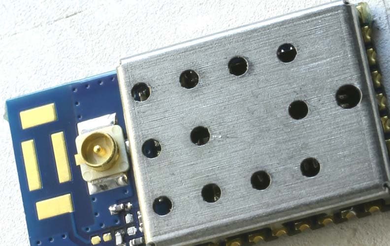
OJM900MCA
Jun 04, 2015Hummingbird MCA
Equipment Class
DSS - Part 15 Spread Spectrum Transmitter
OJM-CMD-HHTX-XXXA
Aug 11, 2010Full Size Handheld Transmitter
Equipment Class
DSC - Part 15 Security/Remote Control Transmitter
OJM-OTX-XXX-CPHSA
Apr 29, 2007Compact Handheld Transmitter
Equipment Class
DSC - Part 15 Security/Remote Control Transmitter
OJM-OTX-XXX-LRHSA
Apr 11, 2007Long-Range Handheld Transmitter
Equipment Class
DSC - Part 15 Security/Remote Control Transmitter
OJM-OTX-XXX-LRMSA
Apr 24, 2006Long-Range Handheld Transmitter
Equipment Class
DSC - Part 15 Security/Remote Control Transmitter