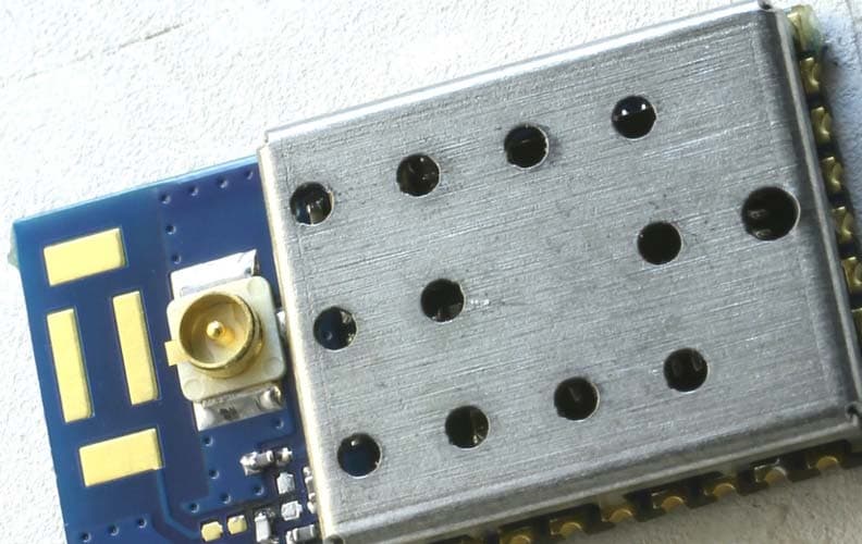
OJM-TR-900-MCLinx RF Transceiver
Linx Technologies
Click to zoom
Application Details
- Equipment Class
- DXT - Part 15 Low Power Transceiver, Rx Verified
- Date of Grant
- Jan 08, 2001
- Application Purpose
- Original Equipment
- Date of Application
- Oct 25, 2000
- Equipment Note
- Linx RF Transceiver
- Frequency Range
- 902.50000000 - 927.50000000
- Company
- Linx Technologies
- Country
- United States
Documents & Files
Document Text
Text extracted from the exhibit documents filed with the FCC. Open a document above to read the original.
Attestation Statements
PUBLIC NOTICE Federal Communications Commission 445 12th St., S.W. Washington, D.C. 20554 News Media Information 202 / 418-0500 Fax-On-Demand 202 / 418-2830 TTY 202 / 418-2555 Internet: http://www.fcc.gov ftp.fcc.gov DA 00- 2225 September 28, 2000 OET Extends Effective Date of Antenna Connector Requirement Indefinitely On May 22, 2000, the Office of Engineering and Technology, OET, issued a Public Notice, DA 00-1087, clarifying 47 CFR 15.203. This rule requires transmitters authorized under Part 15 to be designed in such a way as to ensure that no antenna, other than that furnished by the responsible party, can be used with the device. Typically, a manufacturer will either design a unique antenna connector or modify a commonly available connector to satisfy this requirement. In the Public Notice, we noted several antenna connectors, that were once considered unique, have since become common place and no longer satisfy the requirement of this rule section. Hence, effective 30 days after the date of the Public Notice, these antenna connectors would no longer be acceptable for satisfying the requirement in Section 15.203. On June 22, 2000 we extended the effective date of the antenna connector requirement in the Public Notice to October 1, 2000. However, a Petition for Reconsideration has been filed and, in order to consider the merits of the Petition, we are extending the effective date of the Public Notice indefinitely. After a decision on the merits of the Petition has been made, we will address the need for a new effective date regarding DA 00-1087. Thus, we are extending the effective date of Public Notice, DA 00-1087, indefinitely. For further information concerning this Public Notice, contact Joe Dichoso at the FCC Laboratory, 7435 Oakland Mills Road, Columbia, Md. 21046, (301) 362-3024, or e-mail: [email protected].
Schematics
NOTE ON THE SCHEMATICS The RF Module is normally shown on the schematic itself as an IC with the input and output pins being shown on the Module going to other circuitry and/or components. For this Module, the pins are as follows (pin 1 is the upper left corner and pin 11 is the lower right corner) Left hand side of the Module: For the right hand side of the Module: 1. GND 11. (pin for the output connector) 2. DATA OUT 12. (pin for the output connector) 3. AUDIO 13. (pin for the output connector) 4. RSSI 14. LEV ADJ 5. PDN 15. GND 6. LD 16. CH SEL 0/UDATA 7. RX-TX SEL 17. CH SEL 1/UCLOCK 8. GND 18. CH SEL 2 9. TXDATA 19. NC 10. VIN 20. MODE
Test Report
FCC ID: OJM-TR-900-MC Report No.: B01002D1 114 OLINDA DRIVE, BREA, CALIFORNIA 92823 PHONE: (714) 579-0500 FAX: (714) 579-1850 Page 1 of 16 FCC PART 15, SUBPART C TEST REPORT for LINX RF TRANSCEIVER Model: TR-900-MC-PA Prepared for LINX TECHNOLOGIES 575 SE ASHLEY PLACE GRANTS PASS, OR 97526 COMPATIBLE ELECTRONICS INC. 114 OLINDA DRIVE BREA, CALIFORNIA 92823 (714) 579-0500 DATE: OCTOBER 16, 2000 REPORT APPENDICES TOTAL BODY A B C D PAGES 16 2 2 11 44 75 This report shall not be reproduced except in full, without the written approval of Compatible Electronics. FCC ID: OJM-TR-900-MC Report No.: B01002D1 114 OLINDA DRIVE, BREA, CALIFORNIA 92823 PHONE: (714) 579-0500 FAX: (714) 579-1850 Page 2 of 16 TABLE OF CONTENTS Section / Title PAGE GENERAL REPORT SUMMARY 4 SUMMARY OF TEST RESULTS 4 1. PURPOSE 5 2. ADMINISTRATIVE DATA 6 2.1 Location of Testing 6 2.2 Traceability Statement 6 2.3 Cognizant Personnel 6 2.4 Date Test Sample was Received 6 2.5 Disposition of the Test Sample 6 2.6 Abbreviations and Acronyms 6 3. APPLICABLE DOCUMENTS 7 4. Description of Test Configuration 8 4.1 Description of Test Configuration - EMI 8 4.1.1 Cable Construction and Termination 9 5. LISTS OF EUT, ACCESSORIES AND TEST EQUIPMENT 10 5.1 EUT and Accessory List 10 5.2 EMI Test Equipment 11 6. TEST SITE DESCRIPTION 12 6.1 Test Facility Description 12 6.2 EUT Mounting, Bonding and Grounding 12 7. Test Procedures 13 7.1 Radiated Emissions (Spurious and Harmonics) Test 13 7.2 Band Edge Plots of the Low and High Channels 15 8. CONCLUSIONS 16 FCC ID: OJM-TR-900-MC Report No.: B01002D1 114 OLINDA DRIVE, BREA, CALIFORNIA 92823 PHONE: (714) 579-0500 FAX: (714) 579-1850 Page 3 of 16 LIST OF APPENDICES APPENDIX TITLE A Modifications to the EUT B Additional Models Covered Under This Report C Diagrams, Charts and Photos • Test Setup Diagrams • Radiated Emissions Photos • Antenna and Effective Gain Factors D Data Sheets LIST OF FIGURES FIGURE TITLE 1 Conducted Emissions Test Setup 2 Plot Map And Layout of Test Site FCC ID: OJM-TR-900-MC Report No.: B01002D1 114 OLINDA DRIVE, BREA, CALIFORNIA 92823 PHONE: (714) 579-0500 FAX: (714) 579-1850 Page 4 of 16 GENERAL REPORT SUMMARY This electromagnetic emission test report is generated by Compatible Electronics Inc., which is an independent testing and consulting firm. The test report is based on testing performed by Compatible Electronics personnel according to the measurement procedures described in the test specifications given below and in the "Test Procedures" section of this report. The measurement data and conclusions appearing herein relate only to the sample tested and this report may not be reproduced in any form unless done so in full with the written permission of Compatible Electronics. This report must not be used to claim product endorsement by NVLAP or any other agency of the U.S. Government. Device Tested: Linx RF Transceiver Model: TR-900-MC-PA S/N: 3 Product Description: See Expository Statement. Modifications: The EUT was modified during the testing. Please see the list located in Appendix A. Manufacturer: Linx Technologies 575 SE Ashley Place Grants Pass, OR 97526 Test Dates: September 28 and October 2, 2000 Test Specifications: EMI requirements CFR Title 47, Part 15 Subpart C, Sections 15.205, 15.209, and 15.249 Test Procedure: ANSI C63.4: 1992 Test Deviations: The test procedure was not deviated from during the testing. SUMMARY OF TEST RESULTS TEST DESCRIPTION RESULTS 1 Conducted RF Emissions, 450 kHz - 30 MHz This test was not performed because the EUT is powered by a nine volt battery. 2 Radiated RF Emissions, 10 kHz - 9300 MHz Complies with the limits of CFR Title 47, Part 15, Subpart C, sections 15.205, 15.209, and 15.249 FCC ID: OJM-TR-900-MC Report No.: B01002D1 114 OLINDA DRIVE, BREA, CALIFORNIA 92823 PHONE: (714) 579-0500 FAX: (714) 579-1850 Page 5 of 16 1. PURPOSE This document is a qualification test report based on the Electromagnetic Interference (EMI) tests performed on the Linx RF Transceiver Model: TR-900-MC-PA. The EMI measurements were performed according to the measurement procedure described in ANSI C63.4: 1992. The tests were performed in order to determine whether the electromagnetic emissions from the equipment under test, referred to as EUT hereafter, are within the specification limits defined by CFR Title 47, Part 15, Subpart C, sections 15.205, 15.209, and 15.249. FCC ID: OJM-TR-900-MC Report No.: B01002D1 114 OLINDA DRIVE, BREA, CALIFORNIA 92823 PHONE: (714) 579-0500 FAX: (714) 579-1850 Page 6 of 16 2. ADMINISTRATIVE DATA 2.1 Location of Testing The EMI tests described herein were performed at the test facility of Compatible Electronics, 114 Olinda Drive, Brea, California 92823. 2.2 Traceability Statement The calibration certificates of all test equipment used during the test are on file at the location of the test. The calibration is traceable to the National Institute of Standards and Technology (NIST). 2.3 Cognizant Personnel Linx Technologies Paul True President Compatible Electronics Inc. Kyle Fujimoto Test Engineer Scott McCutchan Lab Manager 2.4 Date Test Sample was Received The test sample was received on September 28, 2000. 2.5 Disposition of the Test Sample The test sample has not been returned to Linx Technologies as of October 16, 2000. 2.6 Abbreviations and Acronyms The following abbreviations and acronyms may be used in this document. RF Radio Frequency EMI Electromagnetic Interference EUT Equipment Under Test P/N Part Number S/N Serial Number HP Hewlett Packard ITE Information Technology Equipment CML Corrected Meter Limit LISN Line Impedance Stabilization Network FCC ID: OJM-TR-900-MC Report No.: B01002D1 114 OLINDA DRIVE, BREA, CALIFORNIA 92823 PHONE: (714) 579-0500 FAX: (714) 579-1850 Page 7 of 16 3. APPLICABLE DOCUMENTS The following documents are referenced or used in the preparation of this EMI Test Report. SPEC TITLE CFR Title 47, Subpart C. FCC Rules – Radio frequency devices (including digital devices) – Intentional R…
Text truncated - open the document above for the full version.
Contact Information
Applicant
Shawn Hogan(VP of Engineering & Operations)
Test Firm
Compatible ElectronicsScott McCutchan
714-579-0500Fax: 714-579-1850
Technical Specifications
| # | Rule Parts | Frequency Range | Power Output |
|---|---|---|---|
| 1 | 15C | 902.5 MHz - 927.5 MHz | - |
Other Applications from Linx Technologies
OJM900MCA
Jun 04, 2015Hummingbird MCA
Equipment Class
DSS - Part 15 Spread Spectrum Transmitter
OJM-CMD-HHTX-XXXA
Aug 11, 2010Full Size Handheld Transmitter
Equipment Class
DSC - Part 15 Security/Remote Control Transmitter
OJM-OTX-XXX-CPHSA
Apr 29, 2007Compact Handheld Transmitter
Equipment Class
DSC - Part 15 Security/Remote Control Transmitter
OJM-OTX-XXX-LRHSA
Apr 11, 2007Long-Range Handheld Transmitter
Equipment Class
DSC - Part 15 Security/Remote Control Transmitter
OJM-OTX-XXX-LRMSA
Apr 24, 2006Long-Range Handheld Transmitter
Equipment Class
DSC - Part 15 Security/Remote Control Transmitter