OK83015HT02FRS/ GMRS
Shenzhen Baoan Hantong Electronics Factory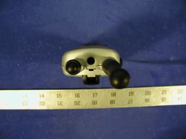
Click to zoom
Application Details
- Equipment Class
- FRF - Part 95 Family Radio Face Held Transmitter
- Date of Grant
- Aug 08, 2002
- Application Purpose
- Original Equipment
- Date of Application
- Aug 07, 2002
- Equipment Note
- FRS/ GMRS
- Frequency Range
- 462.56250000 - 467.71250000
- Country
- China
Documents & Files
Document Text
Text extracted from the exhibit documents filed with the FCC. Open a document above to read the original.
Users Manual
TWO-WAY FAMILY RADIOS MODEL 3015 OWNER'S MANUAL INSTALLATION AND OPERATING INSTRUCTIONS CONGRATULATIONS! You now own a - thoroughly tested to be certain it meets our own top-quality Bell Equipment product exacting quality control and standards. Please take a few moments to review the following important informationbefore using these items. Thank You! FCC NOTICEFRS PRODUCT DESCRIPTION The FCC requires that you be advised of certain requirements involving the use of this device. This equipment has been tested and found to comply with the limits for a Class B digital device, pursuant to Part 15 of the FCC Rules. These limits are designed to provide reasonable protection against harmful interference in residential installation. This device uses and can generate radio frequency energy. If not installed and used in accordance with the instructions, it may cause harmful interference to radio communications. However, there is no guarantee that the interference will not occur in a particular installation. If this equipment does cause harmful interference to radio or television reception (which can be determined by turning the unit off and on), the user is encouraged to correct the interference by one or more of the following measures: Reorient or relocate the receiving antenna. Increase the separation between the equipment and receiver. Connect the equipment to an outlet on a circuit different from that to which the receiver is connected. Consult the dealer or an experienced radio/TV technician for help. This equipment generates or uses radio frequency energy. Changes or modifications not expressly approved in writing may cause harmful interference and void the user's authority to operate this equipment. FCC WARNING: FCC INFORMATION:This device complies with Part 15 of the FCC Rules. Operation is subject to the following two conditions:(1) This device may not cause harmful interference, and (2) this device must accept any interference received, including interference that may cause undesired operation. Privacy of communications SAFETY INFORMATION:Your wireless hand-held portable transceiver contains a low power transmitter. When the PUSH TO TALK (PTT) button is pushed it sends out radio frequency (RF) signals. The device is authorized to operate at a duty factor not to exceed 50%. In August 1996, the Federal Communications Commissions (FCC) adopted RF exposure guidelines with safety levels for hand-held wireless devices. may not be ensured when using this equipment. To maintain compliance with the FCC's RF exposure guidelines hold the transmitter and ANTENNA at least 1 inch (2.5 cm) from your face and speak in a normal voice, with the ANTENNA pointed up and away from the face. If you wear the handset on your body while using the headset accessory, use only the supplied belt clip for this product and when transmitting, take it out of the belt to CAUTION: ensure that the ANTENNA is at least 1 inch (2.5 cm) from your body. Use only the supplied ANTENNA. Unauthorized antennas, modifications, or attachments could damage the transmitter and may violate FCC regulations. The maximum transmission range will vary depending on terrain and environment. Range will be greater in open fields, while the range is shorter within NOTE: and around buildings or large structures. Please read this user's manual thoroughly to get the most out of your FRS3015 two-way radio. The FRS3015 is compatible with other two-way radios using the FRS frequency band (operating in the frequency range from 462.5625MHz to 462.7125MHz and from 467.5625MHz to 467.7125MHz). The FRS3015 is a 22-channel UHF two-way radio, featuring a multi-functional LCD panel (which indicates the current channel and various radio status icons). Other features also include electronic volume control and battery save circuitry. Family Radio Service (FRS) is the newest generation in personal two-way communications. FRS radios operate in a license-free radio band (no FCC license is needed for FRS operation), on any of the 14 license-free channels. The FRS3015 is a lightweight, compact two-way radio that can be used up to about two miles with family or friends at parks, shopping malls, sporting events, concerts--any indoor or outdoor activity! 1 2 15 1. What does the limited warranty cover? 2. What will TT Systems do when I send in my unit? 3. How do I send my unit, in or out of warranty? TT Systems LLC warrants that the PMG-3015 sold by TTSystems within the continental limits of the United States, Hawaii and Alaska are free from defects in materials and workmanship under normal use for one year. This warranty is only applicable to the original purchaser of the PMG-3015, when accompanied by a sales purchase and the name of the company from which it was purchased. This warranty is in lieu of expressed or implied, including any implied warranty of merchantability or fitness, and of any other obligation on the part of TT Systems. At our discretion, repair or replace the PMG-3015. Properly pack your unit. Include any cables and accessories that were originally provided with the product. We recommend using the original carton and packing materials. l l l l l l l l l l l l l l l l Include in the package a copy of the sales receipt or other evidence of date of original purchase (if the unit was purchased within the last year). Print your name, address and phone number, along with a description of the problem, and include this in the package. Include payment for any service or repair not covered by the warranty, as deter- mined by TT Systems. Contact a customer service representative at 1-800-592- 1336 or [email protected] to find out what payment is necessary. Ship the unit via UPS insured or equivalent to: If you have not received your returned unit within 3-4 weeks, you may call 1-914- 968-2100 regarding the status of your return. Damage from misuse, neglect, or acts of nature (lightning, floods, power surges, etc). Products that may have been repaired or altered by …
Text truncated - open the document above for the full version.
External Photos
Shenzhen Bao An Hantong Electronics Factory FCC ID: OK83015HT02 Report # R0206252FCC Part 95 Test Report EUT External Photographs EUT - Top View EUT - Front View Shenzhen Bao An Hantong Electronics Factory FCC ID: OK83015HT02 Report # R0206252FCC Part 95 Test Report EUT - Rear View EUT – Port Side View
Schematics
3015.sch-1 - Mon Jul 01 12:11:52 2002
Schematics
3015.sch-2 - Mon Jul 01 12:12:12 2002
Test Report
Note: This test report is specially limited to the above client company and product model. It may not be duplicated without prior written consent of Bay Area Compliance Laboratory Corporation. This report must not be used by the client to claim product endorsement by NVLAP or any agency of the U.S. Government. FCC PART 95 EMI MEASUREMENT AND TEST REPORT For Shenzhen Bao An Hantong Electronics Factory Block 11 & 12, Jinbi Industrial Area, Hwang Tian, Baoan, Shenzhen, Guangdong, China 518102 FCC ID: OK83015HT02 July 9, 2002 This Report Concerns: Original Report Equipment Type: Family Radio Service (FRS / GMRS) Test Engineer:Benjamin Jin Report Number:R0206252 Test Date:July 5, 2002 Reviewed By:Jeff Lee Prepared By:Bay Area Compliance Laboratory Corporation 230 Commercial Street Sunnyvale, CA 94085 Tel: (408) 732-9162 Fax: (408) 732 9164 Shenzhen Bao An Hantong Electronics Factory FCC ID: OK83015HT02 Report # R0206252FCC Part 95 Test ReportPage 2 of 29 TABLE OF CONTENTS 1 - GENERAL INFORMATION.................................................................................................................................................4 1.1 PRODUCT DESCRIPTION FOR EQUIPMENT UNDER TEST (EUT).........................................................................................4 1.2 OBJECTIVE................................................................................................................................................................................4 1.3 TEST METHODOLOGY.............................................................................................................................................................4 1.4 TEST FACILITY.........................................................................................................................................................................4 1.5 TEST EQUIPMENT LIST............................................................................................................................................................5 2 - SYSTEM TEST CONFIGURATION..................................................................................................................................6 2.1 JUSTIFICATION.........................................................................................................................................................................6 2.2 EUT EXERCISE SOFTWARE....................................................................................................................................................6 2.3 SPECIAL ACCESSORIES............................................................................................................................................................6 2.4 SCHEMATICS / BLOCK DIAGRAM..........................................................................................................................................6 2.5 EQUIPMENT MODIFICATIONS.................................................................................................................................................6 2.6 CONFIGURATION OF TEST SYSTEM.......................................................................................................................................7 2.7 TEST SETUP BLOCK DIAGRAM..............................................................................................................................................7 3 - REQUIREMENTS OF PROVISIONS................................................................................................................................8 3.1 REQUIREMENTS AND TEST SUMMARY.................................................................................................................................8 3.2 LABELING REQUIREMENT......................................................................................................................................................8 4 - EFFECTIVE RADIATED POWER.....................................................................................................................................9 4.1 PROVISION APPLICABLE.........................................................................................................................................................9 4.2 TEST PROCEDURE....................................................................................................................................................................9 4.3 TEST EQUIPMENT...................................................................................................................................................................10 4.4 TEST RESULTS........................................................................................................................................................................10 5 - MODULATION CHARACTERISTICS...........................................................................................................................11 5.1 PROVISION APPLICABLE.......................................................................................................................................................11 5.2 TEST PROCEDURE..................................................................................................................................................................11 5.3 TEST EQUIPMENT..................................................................................................................................................................11 5.4 TEST RESULTS........................................................................................................................................................................11 6 - OCCUPIED BANDWIDTH OF EMISSION...................................................................................................................14 6.1 PROVISION APPLICABLE..................................................................................................................…
Text truncated - open the document above for the full version.
Test Setup Photos
Shenzhen Bao An Hantong Electronics Factory FCC ID: OK83015HT02 Report # R0206252FCC Part 95 Test Report Test Setup Photographs Radiated Emission Setup - Front View Radiated Emission Setup - Rear View
Contact Information
Applicant
Dan Coronia(Senior Engineer)
Test Firm
Bay Area Compliance LaboratoryJohn Chan
Technical Specifications
| # | Rule Parts | Frequency Range | Power Output | Emission | Tolerance |
|---|---|---|---|---|---|
| 2 | 95B | 462.5625 MHz - 467.7125 MHz | 100.00 mW | 11K0F3E | 2.5 ppm |
Other Applications from Shenzhen Baoan Hantong Electronics Factory
OK8ATC2488HT03
Jun 16, 20032.4 GHz 77 Chs DSSS Telephone with Caller ID
Equipment Class
DSS - Part 15 Spread Spectrum Transmitter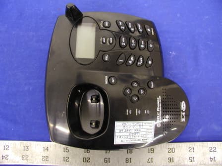
OK836882HT02
Feb 26, 20032.4 GHz Cordless Telephone
Equipment Class
DXX - Part 15 Low Power Communication Device Transmitter
OK839285HT02
Jan 21, 2003900 MHz Cordless Telephone
Equipment Class
DXX - Part 15 Low Power Communication Device Transmitter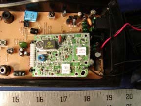
OK839287HT02
Dec 19, 2002900MHz Crdls Caller ID Phn w/ Call Waiting on H/S
Equipment Class
DXT - Part 15 Low Power Transceiver, Rx Verified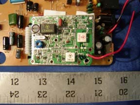
OK836280HT02
Dec 19, 20022.4GHz Filtered TM Snd 50-Chnnl Autoscan Crdls Phn
Equipment Class
DXT - Part 15 Low Power Transceiver, Rx Verified