OK899251HT02FRS/ GMRS
Shenzhen Baoan Hantong Electronics Factory
Click to zoom
Application Details
- Equipment Class
- FRF - Part 95 Family Radio Face Held Transmitter
- Date of Grant
- Aug 08, 2002
- Application Purpose
- Original Equipment
- Date of Application
- Aug 08, 2002
- Equipment Note
- FRS/ GMRS
- Frequency Range
- 462.55000000 - 467.72000000
- Country
- China
Documents & Files
Document Text
Text extracted from the exhibit documents filed with the FCC. Open a document above to read the original.
Users Manual
1 07110A-1 99251 MANUAL Ver.1.0 Page:1 ENGLISH VERSION 99251 MANUAL Ver. 1.0 Page:1 ENGLISH VERSION IMPORTANT SERVICE INFORMATION Read this manual before attempting to setup or use this instrument. It contains important information regarding safe installation and use. Keep this manual for future reference. Also save the carton, packing and proof of purchase to simplify and accelerate any needed action. If you need assistance or service, call (800) 888-8990 between 8:00 a.m. and 4:30 p.m. Pacific Standard Time, Monday through Friday. THIS SYMBOL IS INTENDED TO ALERT THE USER OF THE PRESENCE OF IMPORTANT OPERATING AND MAINTENANCE (SERVICING) INSTRUCTIONS IN THE OWNER'S MANUAL. FCC NOTICE The FCC requires that you be advised of certain requirements involving the use of this device. This 99251 CARTON CONTENTS Two-Way Radio (Pair) User-Replaceable Belt Clip * User's Manual * - Attached to the unit at the time of packaging. 07110A-1 2 99251 Ver. 1.0 Page:2 ENGLISH VERSION 99251 Ver. 1.0 Page:2 ENGLISH VERSION equipment has been tested and found to comply with the limits for a Class B digital device, pursuant to Part 15 of the FCC Rules. These limits are designed to provide reasonable protection against harmful interference in a residential installation. This equipment uses and can generate radio frequency energy. If not installed and used in accordance with the instructions, it may cause harmful interference to radio communications. However, there is no guarantee that the interference will not occur in a particular installation. If this equipment does cause harmful interference to radio or television reception (which can be determined by turning the equipment off and on), the user is encouraged to correct the interference by one or more of the following measures: • Reorient or relocate the receiving antenna. • Increase the separation between the equipment and receiver. • Connect the equipment to an outlet on a circuit different from that to which the receiver is connected. • Consult the manufacturer for technical assistance. FCC INFORMATION: This device complies with Part 15 of the FCC Rules. Operation is subject to the following two conditions: (1) This device may not cause harmful interference, and (2) this device must accept any interference received, including interference that may cause undesired operation. Privacy of communications may not be ensured when using this equipment. FCC WARNING : This equipment generates or uses radio frequency energy. Changes or modifications not expressly approved in writing may cause harmful interference and void the user’s authority to operate this equipment. 3 07110A-1 99251 MANUAL Ver.1.0 Page:3 ENGLISH VERSION 99251 MANUAL Ver. 1.0 Page:3 ENGLISH VERSION SAFETY INFORMATION Your wireless hand-held portable transceiver contains a low power transmitter. When the Push to Talk (PTT) button is pressed it sends out radio frequency (RF) signals. The device is authorized to operate at a duty factor not to exceed 50%. On August 1996, the Federal Communications Commissions (FCC) adopted RF exposure guidelines with safety levels for hand-held wireless devices. CAUTION: To maintain compliance with the FCC’s RF exposure guidelines hold the transmitte r and antenna at least 2 inches (5 centimeters) from your face and speak in a normal voice. With the antenna pointed up and away from the face. If you wear the FRS on your body while using the headset accessory, use only the supplied belt clip for this product. When transmitting take it off the belt to ensure that the antenna is at least 2 inch (5 centimeters) from your body. Use only the supplied antenna. Unauthorized antennas, modifications, or attachments could damage the transmitter and may violate FCC regulations. Warning: Adjustment to this unit or replacement of any transmitter component (crystal, semiconductor, etc.) to this unit that could result in a violation of the rules. 07110A-1 4 99251 Ver. 1.0 Page:4 ENGLISH VERSION 99251 Ver. 1.0 Page:4 ENGLISH VERSION GMRS LICENSING INFORMATION Before any station transmits on any channel authorized in the GMRS from any point within or over the territorial limits of any area where radio services are regulated by the FCC, the responsible party must obtain a license for a GMRS system. An individual 18 years of age or older, who is not a representative of a foreign government, is eligible to apply for a GMRS system license. Application for a GMRS system license is make on FCC form 605 and you can obtain a copy from the FCC’s website: http://www.fccgov/Formpage.html or by calling the FCC’s Form Distribution Center 1- 800-418-FORM(3676), or from the fax-on-demand by dialing (202)418-0177. There is a filing fee. For information on fees, see the FCC’s Website: http://wireless.fcc.gov/csinfo/feeinfo.html . 5 07110A-1 99251 MANUAL Ver.1.0 Page:5 ENGLISH VERSION 99251 MANUAL Ver. 1.0 Page:5 ENGLISH VERSION FRS PRODUCT DESCRIPTION The Family Radio Service (FRS) is the newest generation in personal two-way communication. FRS radios operate in a license-free radio band (no FCC license is needed for FRS operation), on any of the 22 license-free channels. The 99251 is a lightweight, compact two-way radio that can be used with family or friends at parks, shopping malls, sporting events, concerts, or any indoor or outdoor activity! The 99251 are compatible with other two-way radios using the FRS frequency band (operating in the frequency range from 462.5625 MHz to 467.7125 MHz). The 99251 is a 22-channel UHF two-way radio with 38 sub-codes, featuring a multi-functional LCD display (which indicates the current channel and various radio status icons). Other features also include electronic volume control and battery save circuitry. Please read this user's manual thoroughly to get the most out of your FRS two-way radio. NOTE: The maximum transmission range will vary depending on terrain and environment. Range will be greater in open fields, while the range is shorter within / around b…
Text truncated - open the document above for the full version.
External Photos
Shenzhen Bao An Hantong Electronics Factory FCC ID: OK899251HT02 Report # R0206175FCC Part 95 Test Report EUT External Photographs EUT - Top View EUT - Front View Shenzhen Bao An Hantong Electronics Factory FCC ID: OK899251HT02 Report # R0206175FCC Part 95 Test Report EUT - Rear View EUT – Right View Shenzhen Bao An Hantong Electronics Factory FCC ID: OK899251HT02 Report # R0206175FCC Part 95 Test Report EUT – Left View
ID Label/Location Info
Shenzhen Bao An Hantong Electronics Factory FCC ID: OK899251HT02 Report # R0206175FCC Part 95 Test Report FCC ID Labeling and Location Proposed FCC ID Labeling Proposed FCC ID Location Rear Side of EUT FCC ID: OK899251HT02 Proposed FCC ID Location label here
Internal Photos
Shenzhen Bao An Hantong Electronics Factory FCC ID: OK899251HT02 Report # R0206175FCC Part 95 Test Report EUT Internal Photographs EUT – Component View EUT – Solder View
Operational Description
LIONDA TECHNOLOGY COMPANY LIMITEDLIONDA TECHNOLOGY COMPANY LIMITED Lionda Research and Development CenterLionda Research and Development Center 99251seriesdesc Page 1 8/9/02 CIRCUIT DESCRIPTION Model: 99251-(x) a. Receiver Section Radio Frequency signal received by the antenna (ANT1), passing through the Low Pass Filter (L2-L3, C30-C31). The RF signal is then amplified by Low Noise Amplifier Q2 and passes through a Band Pass Filter FL1 (465MHz). The filtered signal within the range of 462 MHz – 467 MHz is then mixed with the first local oscillator signal from the Voltage Controlled Oscillator (VCO) circuit (Q19-Q21, D5, L17) through Q11, a portion of VCO signal is then feedback to the PLL IC (IC5) for phase comparison generating a stable RX Frequency, the output signal is filtered by FL2 (21.7 MHz) which is the first Intermediate Frequency (IF) and is then amplified by Q14. The IF signal is fed to the discriminator IC (IC2) pin 16 which is then mixed with the second local oscillator supplied by crystal X2 (21.65 MHz) to produced and reduced second IF signal. Demodulated signal is recovered through correct adjustment of IF coil (L13) and the internal discriminator circuit of IC2. The recovered Audio signal is outputted at pin 9 of IC2 and then processed through filtering done by U3-D circuit, the fully recovered audio signal is then further amplified by Power Amplifier U3-A. An audible sound is therefore produce by the speaker SPK1, which can be varied from minimum to maximum through the key function (up/down) and process by the CPU IC6. b. Transmitter Section PTT switch when pushed triggers the Transmitter Circuit “ON”, the voice signal generates by the surrounding noise passes through the Microphone MIC1 where mechanical to electrical transformation occurs, the electrical transformed signal is then filtered by a Band Pass Filter U3-A, D, and C. The output signal is Modulated by a modulator circuit with a varactor diode D8 and L17. The external components from Q19-Q21 form a VCO Circuit, which generates the required oscillating frequency for transmission; a portion of this signal is feedback to the PLL IC5 pin 14 for phase comparison in order to produce a stabilized TX frequency. The modulated signal is then amplified by a Cascaded Amplifier Circuit Q17 and Q18 and again amplified by Q24 to produce a sufficient Radio Frequency signal emitted by the Antenna (ANT1). c. Call Transmission By pushing the CALL key, a signal is detected by the CPU (IC6), a CALL data is then produced by the CPU. This data passes through the Band Pass Filter U1-C and modulated by the varactor diode D2 and L8. The signal follows it’s conventional transmission section path through the antenna. d. Continuous Tone Coded Squelch Signal Protocol Once the unit is set to the corresponding Channel and CTCSS code at TX mode a tone is continuously generated from CPU through R96 and R103 and then passes through U1C for filtering and amplification. Then the Coded Tone signal follows its conventional transmission section path. During receiving mode once the Coded Tone signal matched with the set Code the CPU acknowledges and RX mute will disabled and RX will be active. LIONDA TECHNOLOGY COMPANY LIMITEDLIONDA TECHNOLOGY COMPANY LIMITED Lionda Research and Development CenterLionda Research and Development Center 99251seriesdesc Page 2 8/9/02 e. Battery Low Detection Battery Low Detection is controlled by the IC6 as detected on the LCD1, however a voltage divider circuit R50 and R51 serve as the stabilize reference voltage for the IC6 to process its detection. f. Squelch Detection Supported by the linear IC circuit (IC2), a variable resistor VR1 sets the level of detection and Diode D11 acts as a comparator circuit interface with the CPU IC6. g. Power Supply Supply voltage of 6 Volts dc is needed to power “ON” the whole circuitry, by four (4) batteries “AAA” size. FREQUENCY CHART CHANNEL DISPLAY CHANNEL TYPE FREQ (MHz) POWER (Watts) CHANNEL DISPLAY CHANNEL TYPE FREQ (MHz) POWER (Watts) 1 GMRS/FRS 462.5625 0.190 12 FRS 467.6625 0.190 2 GMRS/FRS 462.5875 0.190 13 FRS 467.6875 0.190 3 GMRS/FRS 462.6125 0.190 14 FRS 467.7125 0.190 4 GMRS/FRS 462.6375 0.190 15 GMRS 462.5500 0.190 5 GMRS/FRS 462.6625 0.190 16 GMRS 462.5750 0.190 6 GMRS/FRS 462.6875 0.190 17 GMRS 462.6000 0.190 7 GMRS/FRS 462.7125 0.190 18 GMRS 462.6250 0.190 8 FRS 467.5625 0.190 19 GMRS 462.6500 0.190 9 FRS 467.5875 0.190 20 GMRS 462.6750 0.190 10 FRS 467.6125 0.190 21 GMRS 462.7000 0.190 11 FRS 467.6375 0.190 22 GMRS 462.7250 0.190 CTCSS CODE FREQUENCY CHART CODE FREQUENCY (Hz) CODE FREQUENCY (Hz) 1 67.0 20 131.8 2 71.9 21 136.5 3 74.4 22 141.3 4 77.0 23 146.2 5 79.7 24 151.4 6 82.5 25 156.7 7 85.4 26 162.2 8 88.5 27 167.9 9 91.5 28 173.8 10 94.8 29 179.9 11 97.4 30 186.2 12 100.0 31 192.8 13 103.5 32 203.5 14 107.2 33 210.7 15 110.9 34 218.1 16 114.8 35 225.7 17 118.8 36 233.6 18 123.0 37 241.8 19 127.3 38 250.3
Schematics
9917gmrs.sch-1 - Fri Jun 14 10:57:29 2002
Schematics
9917gmrs.sch-2 - Fri Jun 14 10:57:48 2002
Test Report
Note: This test report is specially limited to the above client company and product model. It may not be duplicated without prior written consent of Bay Area Compliance Laboratory Corporation. This report must not be used by the client to claim product endorsement by NVLAP or any agency of the U.S. Government. FCC PART 95 EMI MEASUREMENT AND TEST REPORT For Shenzhen Bao An Hantong Electronics Factory Block 11 & 12, Jinbi Industrial Area, Hwang Tian, Baoan, Shenzhen, Guangdong, China 518102 FCC ID: OK899251HT02 July 9, 2002 This Report Concerns: Original Report Equipment Type: FRS / GMRS Test Engineer:Jeff Lee Report Number:R0206175 Test Date:June 20, 2002 Reviewed By:Benjamin Jin Prepared By:Bay Area Compliance Laboratory Corporation 230 Commercial Street Sunnyvale, CA 94085 Tel: (408) 732-9162 Fax: (408) 732 9164 Shenzhen Bao An Hantong Electronics Factory FCC ID: OK899251HT02 Report # R0206175FCC Part 95 Test ReportPage 2 of 31 TABLE OF CONTENTS 1 - GENERAL INFORMATION.................................................................................................................................................4 1.1 PRODUCT DESCRIPTION FOR EQUIPMENT UNDER TEST (EUT).........................................................................................4 1.2 OBJECTIVE................................................................................................................................................................................4 1.3 TEST METHODOLOGY.............................................................................................................................................................4 1.4 TEST FACILITY.........................................................................................................................................................................4 1.5 TEST EQUIPMENT LIST............................................................................................................................................................5 2 - SYSTEM TEST CONFIGURATION..................................................................................................................................6 2.1 JUSTIFICATION.........................................................................................................................................................................6 2.2 EUT EXERCISE SOFTWARE....................................................................................................................................................6 2.3 SPECIAL ACCESSORIES............................................................................................................................................................6 2.4 SCHEMATICS / BLOCK DIAGRAM..........................................................................................................................................6 2.5 EQUIPMENT MODIFICATIONS.................................................................................................................................................6 2.6 CONFIGURATION OF TEST SYSTEM.......................................................................................................................................7 2.7 TEST SETUP BLOCK DIAGRAM..............................................................................................................................................7 3 - REQUIREMENTS OF PROVISIONS................................................................................................................................8 3.1 REQUIREMENTS AND TEST SUMMARY.................................................................................................................................8 3.2 LABELING REQUIREMENT......................................................................................................................................................8 4 - EFFECTIVE RADIATED POWER.....................................................................................................................................9 4.1 PROVISION APPLICABLE.........................................................................................................................................................9 4.2 TEST PROCEDURE....................................................................................................................................................................9 4.3 TEST EQUIPMENT...................................................................................................................................................................10 4.4 TEST RESULTS........................................................................................................................................................................10 5 - MODULATION CHARACTERISTICS...........................................................................................................................11 5.1 PROVISION APPLICABLE.......................................................................................................................................................11 5.2 TEST PROCEDURE..................................................................................................................................................................11 5.3 TEST EQUIPMENT..................................................................................................................................................................11 5.4 TEST RESULTS........................................................................................................................................................................11 6 - OCCUPIED BANDWIDTH OF EMISSION...................................................................................................................14 6.1 PROVISION APPLICABLE......................................................................................................................................…
Text truncated - open the document above for the full version.
Test Setup Photos
Shenzhen Bao An Hantong Electronics Factory FCC ID: OK899251HT02 Report # R0206175FCC Part 95 Test Report Test Setup Photographs Radiated Emission Setup - Front View Radiated Emission Setup - Rear View
Contact Information
Applicant
Dan Coronia(Senior Engineer)
Test Firm
Bay Area Compliance LaboratoryJohn Chan
Technical Specifications
| # | Rule Parts | Frequency Range | Power Output | Emission | Tolerance |
|---|---|---|---|---|---|
| 2 | 95A | 462.55 MHz - 467.72 MHz | 190.00 mW | 10K9F3E | 2.5 ppm |
Other Applications from Shenzhen Baoan Hantong Electronics Factory
OK8ATC2488HT03
Jun 16, 20032.4 GHz 77 Chs DSSS Telephone with Caller ID
Equipment Class
DSS - Part 15 Spread Spectrum Transmitter
OK836882HT02
Feb 26, 20032.4 GHz Cordless Telephone
Equipment Class
DXX - Part 15 Low Power Communication Device Transmitter
OK839285HT02
Jan 21, 2003900 MHz Cordless Telephone
Equipment Class
DXX - Part 15 Low Power Communication Device Transmitter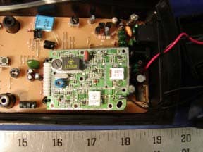
OK839287HT02
Dec 19, 2002900MHz Crdls Caller ID Phn w/ Call Waiting on H/S
Equipment Class
DXT - Part 15 Low Power Transceiver, Rx Verified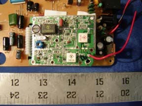
OK836280HT02
Dec 19, 20022.4GHz Filtered TM Snd 50-Chnnl Autoscan Crdls Phn
Equipment Class
DXT - Part 15 Low Power Transceiver, Rx Verified