OK8TT3815HT022.4GHz 50-Channel Basic Analog Cordless Telephone
Shenzhen Baoan Hantong Electronics Factory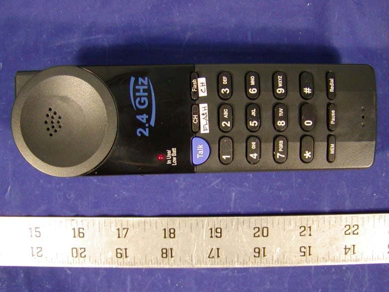
Click to zoom
Application Details
- Equipment Class
- DXT - Part 15 Low Power Transceiver, Rx Verified
- Date of Grant
- Aug 20, 2002
- Application Purpose
- Original Equipment
- Date of Application
- Aug 20, 2002
- Equipment Note
- 2.4GHz 50-Channel Basic Analog Cordless Telephone
- Frequency Range
- 2472.21500000 - 2476.93900000
- Country
- China
Documents & Files
Document Text
Text extracted from the exhibit documents filed with the FCC. Open a document above to read the original.
Users Manual
MODEL: PMP-3815 2.4GHZ CORDLESS TELEPHONE Please read this manual carefully prior to using the telephone. 600-1510602-A INSTALLATION AND OPERATING GUIDE This symbol is to alert you to important operating or servicing instructions that may appear in the user's manual. Always follow basic safety precautions when using this product to reduce the risk of injury, fire, or electrical shock. When using this product, basic safety precautions should always be followed to reduce the risk of fire, electric shock and injury to persons, including the following: 1.Read and understand all instructions. 2.Follow all warnings and instructions marked on the product. 3.Use only with class 2 power source DC 9V 300mA. 4.Unplug this product from the wall outlet before cleaning. Do not use liquid cleaners or aerosol cleaners. Use a damp cloth for cleaning. 5.Do not use this product near water; for example, near a bathtub, wash bowl, kitchen sink or laundry tub, in a wet basement or near a swimming pool. 6.Do not place this product on an unstable cart, stand, or table. The product may fall, causing serious damage to the product. 7.Slots and openings in the cabinet back or bottom are provided for ventilation. To protect it from overheating, these openings must not be blocked or covered. The openings should never be blocked by placing the product on the bed, sofa, rug, or other similar surface. This product should never be placed near or over a radiator or heat register. This product should not be placed in an enclosed environment unless proper ventilation is provided. 8.Do not allow anything to rest on the power cord. Do not locate this product where the cord will be abused by animals or persons walking on it. 9.Do not overload wall outlets and extension cords as this can result in risk of fire or electrical shock. 10. Never push objects of any kind into this product through cabinet slots as they may touch dangerous voltage points or short out parts that could result in a risk of fire or electrical shock. Never spill liquid of any kind on the product. 11. To reduce the risk of electrical shock, do not disassemble this product. Instead take it to a qualified service person when service or repair work is required. Opening or removing covers may expose you to dangerous voltages or other risks. Incorrect re-assembly can cause electrical shock when the appliance is subsequently used. 12. Unplug all cords and refer servicing to qualified service personnel under the following conditions: A. When the power supply cord or plug is damaged or frayed. B. If liquid has been spilled into the product. C. If the product has been exposed to rain or water. D. If the product does not operate normally by following the operating instructions. Adjust only those controls covered in the operating instructions. Improper adjustment of other controls may result in damage and require work by a qualified technician to restore the product to normal operation. 13. Avoid using a telephone (other than a cordless type) during an electrical storm. There may be a remote risk of electric shock from lightning. 14. Do not use a telephone to report a gas leak in the vicinity of the leak. IF YOUR PRODUCT UTILIZES BATTERIES, THE FOLLOWING ADDITIONAL PRECAUTIONS SHOULD BE OBSERVED: 1.Use only the type and size of batteries specified in the users manual. 2.Do not dispose of batteries in a fire. The cells may explode. Check with local codes for possible special disposal instructions. 3.Do not open or mutilate the batteries. Released electrolyte is corrosive and may cause damage to the eyes or skin. It may be toxic if swallowed. 4.Exercise care in handling batteries in order not to short the battery with conducting materials such as rings, bracelets and keys. The battery or conductor may overheat and cause burns. 5.Do not attempt to recharge the batteries with or identified for use with this product. The batteries may leak corrosive electrolyte or explode. 6.Do not attempt to rejuvenate the batteries provided with or identified for use with this product by heating them. Sudden release of the battery electrolyte may occur causing burns or irritation to eyes or skin. 7.When replacing batteries, all batteries should be replaced at the same time. Mixing fresh and discharged batteries could increase internal cell pressure and rupture the discharged batteries. 8.When inserting the batteries into this product, the proper polarity or direction must be observed. Reverse insertion of batteries can cause charging, which may result in leakage or explosion. If a battery is installed incorrectly it may explode. 9.Remove the batteries from this product if the product will not be used for a long period of time (several months or more) since during this time the batteries could leak, damaging the product. 10. Discard "dead" batteries as soon as possible since they are more likely to leak in a product. 11. Do not store this product, or the batteries provided with or for identified use with this product, in high temperature areas. 12. If your product uses a rechargeable battery, charge the battery(ies) only in accordance with the instructions and limitation specified in the User Manual. SAVE THESE INSTRUCTIONS IMPORTANT SAFETY INSTRUCTIONS 2 Important Safety Instructions .........2 FCC Regulations..........................3-4 Battery Cautionary Instructions .....5 PMP-3815 Parts Checklist ...............6 Location of Controls and Features ......................................7-11 Handset .......................................7-8 Base ..........................................9-10 Choosing a Location .....................11 Telephone Setup.......................12-14 Connecting the Base ....................12 Wall Mounting ...............................13 Tone/Pulse Switch ........................14 Battery Installation........................15 Battery Duration ............................15 When the Battery Needs Charging .......................................15 When to …
Text truncated - open the document above for the full version.
Block Diagram
PMP3815BBD.sch-1 - Mon Aug 12 17:11:41 2002 PMP3815HBDsch.sch-1 - Mon Jul 08 17:52:52 2002
External Photos
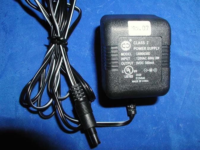
EXHIBIT C - EUT PHOTOGRAPHS Base Chassis - Front View Base Chassis - Rear View Handset Chassis - Top View Handset Chassis - Bottom View Base - Power Adapter
ID Label/Location Info
EXHIBIT A - FCC PRODUCT LABELING AND WARNING STATEMENT FCC ID Label Specifications: Text is black or white in color and is left justified. Labels are silk-screened and shall be “permanently affixed” at a conspicuous location on the EUT. Proposed Label Location on EUT Bottom Side of Base/Proposed FCC ID Label Location / Handset FCC Warning Statement A FCC Warning Statement is provided in the product manual. FCC ID: EW780-1005-00 This device complies with Part 15 of the FCC Rules. Operation is subject to the following two conditions: (1) this device may not cause harmful interference, and (2) this device must accept any interference received, including interference that may cause undesired operation. Privacy of communications may not be ensured when using this phone. 2.1875" 1.0" FCC ID: OK8TT3815HT02
Internal Photos
Base Main Board - Component View Base Main Board - Solder View Base Transceiver - Component View Base Transceiver - Solder View Handset Main Board - Component View Handset Main Board - Solder View Handset Transceiver - Component View Handset Transceiver - Solder View
Operational Description
LIONDA TECHNOLOGY COMPANY LIMITED Lionda Research and Development Center PMP3815 TestMode.doc 1 07/08/02 Test Mode Procedure for PMP-3815XX Note: The default channel frequency is CH25 for both the Base Unit (B/U) and the Handset (H/S). Refer to the Frequency Table for proper frequency allocations. Base Basic Test Mode: Insert the 12Vdc plug into the B/U DC jack while pressing the “Page” key. Both RX and TX will be activated and basic testing can be done. Press the “Page” key to scan the channel frequency one at a time. Handset: Insert the battery into the H/S battery socket while pressing the “*” key. Both RX and TX will be activated and basic testing can be done. Press the “*” key to scan the channel frequency one at a time. LIONDA TECHNOLOGY COMPANY LIMITED Lionda Research and Development Center PMP3815 TestMode.doc 2 07/08/02 2.4GHz PMP-3815XX FREQUENCY CHART B A S E H A N D S E T B A S E H A N D S E T CH TX RX TX RX CH TX RX TX RX 1 2400.592 2472.215 2472.215 2400.592 26 2403.002 2474.625 2474.625 2403.002 2 2400.688 2472.312 2472.312 2400.688 27 2403.098 2474.722 2474.722 2403.098 3 2400.785 2472.408 2472.408 2400.785 28 2403.195 2474.818 2474.818 2403.195 4 2400.881 2472.504 2472.504 2400.881 29 2403.291 2474.914 2474.914 2403.291 5 2400.977 2472.601 2472.601 2400.977 30 2403.387 2475.011 2475.011 2403.387 6 2401.074 2472.697 2472.697 2401.074 31 2403.484 2475.107 2475.107 2403.484 7 2401.170 2472.794 2472.794 2401.170 32 2403.580 2475.204 2475.204 2403.580 8 2401.267 2472.890 2472.890 2401.267 33 2403.677 2475.300 2475.300 2403.677 9 2401.363 2472.986 2472.986 2401.363 34 2403.773 2475.396 2475.396 2403.773 10 2401.459 2473.083 2473.083 2401.459 35 2403.869 2475.493 2475.493 2403.869 11 2401.556 2473.179 2473.179 2401.556 36 2403.966 2475.589 2475.589 2403.966 12 2401.652 2473.276 2473.276 2401.652 37 2404.062 2475.686 2475.686 2404.062 13 2401.749 2473.372 2473.372 2401.749 38 2404.159 2475.782 2475.782 2404.159 14 2401.845 2473.468 2473.468 2401.845 39 2404.255 2475.878 2475.878 2404.255 15 2401.941 2473.565 2473.565 2401.941 40 2404.351 2475.975 2475.975 2404.351 16 2402.038 2473.661 2473.661 2402.038 41 2404.448 2476.071 2476.071 2404.448 17 2402.134 2473.758 2473.758 2402.134 42 2404.544 2476.168 2476.168 2404.544 18 2402.231 2473.854 2473.854 2402.231 43 2404.640 2476.264 2476.264 2404.640 19 2402.327 2473.950 2473.950 2402.327 44 2404.737 2476.360 2476.360 2404.737 20 2402.423 2474.047 2474.047 2402.423 45 2404.833 2476.457 2476.457 2404.833 21 2402.520 2474.143 2474.143 2402.520 46 2404.930 2476.553 2476.553 2404.930 22 2402.616 2474.240 2474.240 2402.616 47 2405.026 2476.650 2476.650 2405.026 23 2402.713 2474.336 2474.336 2402.713 48 2405.122 2476.746 2476.746 2405.122 24 2402.809 2474.432 2474.432 2402.809 49 2405.219 2476.842 2476.842 2405.219 25 2402.905 2474.529 2474.529 2402.905 50 2405.315 2476.939 2476.939 2405.315 SHENZHEN BAOAN HANTONG ELECTRONICS FACTORY Block 11 & 12, Jinbi Industrial Area, Hwangtian, Baoan, Shenzhen, China. TEL.: +86-755-7506252 FAX: +86-755-7506248 SECURITY CODE INFORMATION The PMP-3815XX, PMG-3815XX, IBM-3815XX, BE-3815XX, TT-3815XX, SB- 3860XX cordless telephone uses a digital coding security system to prevent unauthorized use of telephone line by other cordless phones nearby. It has 65,536 possible security code combinations. Each combination of the code is randomly generated every time the handset is picked up. Communication between Handset and the Base unit may not be possible in any of the following situations: 1. After a power failure. 2. After relocating the Base unit by disconnecting the AC adaptor. 3. After replacing the Handset battery. 4. The Handset goes out of range from the Base unit. To reset, place the Handset on the Base unit for 2 to 3 seconds. FCC ID: OK8TT3815HT
Test Report
Note: This test report is specially limited to the above client company and the product model only. It may not be duplicated without prior written consent of Bay Area Compliance Laboratory Corporation. This report must not be used by the client to claim product endorsement by NVLAP or any agency of the U.S. Government. FCC PART 15 SUBPART C EMI MEASUREMENT AND TEST REPORT For Shenzhen Baoan Hantong Electronics Factory Block 11 & 12, Jinbi Industrial Area Hwangtian, Baoan, Shenzhen, China FCC ID: OK8TT3815HT02 August 14, 2002 This Report Concerns: Original Report Equipment Type: 2.4GHz Cordless Telephone Test Engineer: Benjamin Jing Report No.: R0207153 Test Date: July 31, 2002 Reviewed By: Jeff Lee Prepared By: Bay Area Compliance Laboratory Corporation 230 Commercial Street Sunnyvale, CA 94085 Tel: (408) 732-9162 Fax: (408) 732-9164 Shenzhen Baoan Hantong Electronics Factory FCC ID: OK8TT3815HT02 Report # R0207153Rpt Page 2 of 15 FCC Part 15 Subpart C TABLE OF CONTENTS 1 - GENERAL INFORMATION..................................................................................................................................3 1.1 PRODUCT DESCRIPTION FOR EQUIPMENT UNDER TEST (EUT) ..............................................................................3 1.2 OBJECTIVE.............................................................................................................................................................3 1.3 RELATED SUBMITTAL(S)/GRANT(S).......................................................................................................................3 1.4 TEST METHODOLOGY............................................................................................................................................3 1.5 TEST FACILITY.......................................................................................................................................................3 1.6 TEST EQUIPMENT LIST...........................................................................................................................................4 1.7 LOCAL SUPPORT EQUIPMENT LIST AND DETAILS...................................................................................................4 1.8 EXTERNAL I/O CABLING LIST AND DETAILS.........................................................................................................4 2 - SYSTEM TEST CONFIGURATION.....................................................................................................................5 2.1 DESCRIPTION OF TEST CONFIGURATION................................................................................................................5 2.2 EQUIPMENT MODIFICATIONS.................................................................................................................................5 2.3 CONFIGURATION OF TEST SYSTEM.........................................................................................................................5 2.4 TEST SETUP BLOCK DIAGRAM...............................................................................................................................5 3 - CONDUCTED EMISSIONS ...................................................................................................................................6 3.1 MEASUREMENT UNCERTAINTY..............................................................................................................................6 3.2 EUT SETUP............................................................................................................................................................6 3.3 SPECTRUM ANALYZER SETUP................................................................................................................................6 3.4 TEST PROCEDURE..................................................................................................................................................6 3.5 SUMMARY OF TEST RESULTS.................................................................................................................................7 3.6 CONDUCTED EMISSIONS TEST DATA.....................................................................................................................7 3.7 PLOT OF CONDUCTED EMISSIONS TEST DATA.......................................................................................................7 4 - RADIATED EMISSIONS .......................................................................................................................................8 4.1 MEASUREMENT UNCERTAINTY..............................................................................................................................8 4.2 EUT SETUP............................................................................................................................................................8 4.3 SPECTRUM ANALYZER SETUP................................................................................................................................8 4.4 TEST PROCEDURE..................................................................................................................................................8 4.5 CORRECTED AMPLITUDE & MARGIN CALCULATION.............................................................................................9 4.6 SUMMARY OF TEST RESULTS.................................................................................................................................9 4.7 RADIATED EMISSIONS TEST RESULT DATA.........................................................................................................10 5 - BAND EDGES TESTING .....................................................................................................................................12 5.1 TEST PROCEDURE................................................................................................................................................12 5.…
Text truncated - open the document above for the full version.
Test Setup Photos
EXHIBIT B - TEST SETUP PHOTOGRAPHS Base Conducted Emission - Front View Base Conducted Emission - Rear View Base Radiated Emission - Front View Base Radiated Emission - Rear View Handset Radiated Emission - Front View Handset Radiated Emission - Rear View
Contact Information
Applicant
Dan Coronia(Senior Engineer)
Test Firm
Bay Area Compliance LaboratoryJohn Chan
Technical Specifications
| # | Rule Parts | Frequency Range | Power Output |
|---|---|---|---|
| 2 | 15C | 2.47 GHz - 2.48 GHz | - |
Other Applications from Shenzhen Baoan Hantong Electronics Factory
OK8ATC2488HT03
Jun 16, 20032.4 GHz 77 Chs DSSS Telephone with Caller ID
Equipment Class
DSS - Part 15 Spread Spectrum Transmitter
OK836882HT02
Feb 26, 20032.4 GHz Cordless Telephone
Equipment Class
DXX - Part 15 Low Power Communication Device Transmitter
OK839285HT02
Jan 21, 2003900 MHz Cordless Telephone
Equipment Class
DXX - Part 15 Low Power Communication Device Transmitter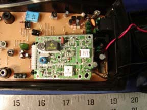
OK839287HT02
Dec 19, 2002900MHz Crdls Caller ID Phn w/ Call Waiting on H/S
Equipment Class
DXT - Part 15 Low Power Transceiver, Rx Verified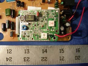
OK836280HT02
Dec 19, 20022.4GHz Filtered TM Snd 50-Chnnl Autoscan Crdls Phn
Equipment Class
DXT - Part 15 Low Power Transceiver, Rx Verified