OKUCHT914NHOME THEATER SPEAKER SYSTEM WITH BLUETOOTH
Shenzhen Junlan Electronic Ltd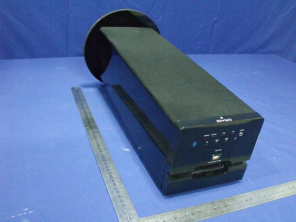
Click to zoom
Application Details
- Equipment Class
- DSS - Part 15 Spread Spectrum Transmitter
- Date of Grant
- Jan 16, 2013
- Application Purpose
- Original Equipment
- Date of Application
- Jan 16, 2013
- Equipment Note
- HOME THEATER SPEAKER SYSTEM WITH BLUETOOTH
- Frequency Range
- 2402.00000000 - 2480.00000000
- Country
- China
Documents & Files
Document Text
Text extracted from the exhibit documents filed with the FCC. Open a document above to read the original.
Users Manual
TOWER STEREO SYSTEM TOWER STEREO SYSTEM Owner's Manual PLEASE READ BEFORE OPERATINGTHIS EQUIPMENT. Model: CHT914n IMPORTANT SAFETY INSTRUCTIONS Insert the AC plug into a conveniently located AC outlet having AC 120V~60Hz. NOTE: The AC plug supplied with the unit is polarized to help minimize the obsolete outlet. possibility of electric shock. If the AC plug dose not fit into a non polarized AC outlet, do not file or cut the wide blade. It is the user's responsibility to have an electrician replacing the 1. Plastic Holder 2. Remote Sensor 3. Speakers 4. Speaker Net 5. Wooden Base 6. Washers 1 2 3 5 6 7 3 7. Screws MAIN UNIT-- RIGHT CHANNEL SPEAKER 1 LEFT CHANNEL SPEAKER 4 5 3 1 1. Speakers 2. Speaker Net 3. Wooden Base 4. Screws 5. Washers Note: 1. Assemble the wooden base to the main body with the supplied screws and washers as Fig. 2 & 4 above. 2.The speaker net can be taken out and reassembled as Fig.1 & 3 above. Figure 3 2 4 Figure 4 Figure 2 Figure 1 i Figure 5 3.Install the Plastic Holder i External Device Plastic Holder on the top of unit to hold the external device as Fig. 5 above. POWER SOURCE INSTALLATION 7. / (Play/Pause) button 8. TUNE - button 9. AUX IN 2 jack 10. 11. SOURCE indicator 1. USB Port (For recharge only) 2. 3. STANDBY indicator 4. SOURCE button 5. / TUNE + button VOL- (Volume Down) button 6. VOL+ (Volume Up) button 12. 13. AUX IN 1 jacks 14. FM Antenna (Power) button 12 13 14 1 2 3 9 4 5 6 7 8 10 11 MAIN UNIT Speaker Connector (For Left Channel Speaker) LOCATION OF CONTROLS 1 2 3 4 5 6 7 8 REMOTE CONTROL 1. POWER button 2. /TUNE - button 3. VOL (Volume)+/- buttons 4. SOURCE button 5. (Mute) button 6. / TUNE+ button 7 (Play/Pause) button 8 EQ (Equalizer) button 7 LOCATION OF CONTROLS Fig.1Fig.2Fig.3 BATTERY PRECAUTIONS EFFECTIVE DISTANCE OF REMOTE TRANSMITTER Approx.15 feet -First Time Use Remove and discard the insulation tab as figure on the right -Replacing Batteries For Remote Control 1. Push and slide out the battery holder as figure 1 below. 2. Replace the battery with a new CR2025 button cell as the polarity markings on the rear of the Remote Control. 3. Close the battery holder. . Remote Sensor, on the front of main unit BATTERY INSTALLATION--- REMOTE CONTROL 7 GENERAL OPERATIONS LEFT SPEAKER CONNECTION Black wire Red wire Main Unit Left Speaker Connect the connection wires (Red and Black) from Left Speaker to the Speaker Connectors on the rear of Main Unit as the figure above. 1.Insert the AC Power Cord into conveniently located AC outlet having AC 120V~60Hz.The Red Standby Indicator will light. 2.Press Power button on the Unit or Remote Control to power on the unit. The Red Standby Indicator will turn off and source Indicator will light. corresponding color as below: 3.Press the SOURCE button repeatedly to switch to desired mode.The source Indicator will turn to ~ Green: Radio ~ Blue: Bluetooth ~ Purple: AUX IN 1 ~ Orange: AUX IN 2 4.During Playback: ~ Press the VOL (Volume) buttons to adjust volume level as desired. ~ Press EQ button repeatedly to select and set equalizer mode as desired. ~ Press (Mute) button on the Remote Control to turn off the sound. Press again to resume. 5.When finished listening, press Power button to power off the unit. The source Indicator will turn off and Red Standby Indicator will light. wall outlet if a long period of time will not use. NOTE: For saving energy, unplug the Power AC Cord from FM Antenna LISTEN TO FM RADIO 1.Power ON the unit as previous procedures. 2.Press the SOURCE button repeatedly until the color of source Indicator turns Green. 4.Repeat the same procedures until the desired radio station is received. NOTE: If the received FM station is in stereo mode, the unit will play it in stereo mode automatically. 3.Press and hold the /TUNE - or /TUNE + buttons until the source Indicator start blinking. The unit will start to search next (or previous) available FM radio station then plays. The Antenna wire on the rear of Main Unit is for radio reception. If reception is weak, unwind and extend the wire or relocate the wire to improve the radio reception. MP3 Player; Discman ... etc.). White Red LISTEN TO TV/DVD/VCR/DVR X IN 1 Audio out jacks on TV/DVD/ VCR/DVR DVD R L AUX IN 1 N 1 4. Press SOURCE button repeatedly until the indicator turns Purple. 1. Connect one end of RCA audio connection cable (not supplied) to the AUX IN 1 jacks on the rear of the unit as the figure above. 2. Connect the other end to the AUX out jacks on the external player (such as Television, VCR, DVD Player, DVR ... etc.). 5. Play the music in the external player as usual. (Make sure the volume output level of the player is in high level. Otherwise, sound from this unit is weak). 8 3. Power on the unit as previous procedures. 9 3. Power on the unit as previous procedures. 4. Press the SOURCE button repeatedly until the color of source Indicator turns Orange. 1. Connect one end of supplied audio connection cable to the AUX IN 2 jack on the top of the unit. 2. Connect the other end to the AUX out/Line out/Phone jack on the external player (such like iPod, iPhone, iPad, MP3 Player, Discman... etc.). 5. Play the music in the external player as usual. (Make sure the volume output level of the player is in high level. Otherwise, sound from this unit is weak). as the figure above. LISTEN TO EXTERNAL AUDIO DEVICES AUX IN 2 jack 10 BLUETOOTH PARING AND PLAYBACK 1. Power on the unit as previous procedures. 2. Press the SOURCE button on the unit or remote control until the indicator turns blue. 3. Turn on the BT function on the external BT device and play the music as usual. (Make sure the volume level of the external BT device is set to high level). 4. During palyback: Press the VOL (Volume) +/- buttons to adjust volume level. Press the / TUNE- or / TUNE + button to skip track. Press the (Play/Pause) button to pause. Press again to to resume normal playback. NOTES: 1. During the first time use, pair the external BT device as below: A. Power on the unit a…
Text truncated - open the document above for the full version.
ID Label/Location Info
4 . 0 m m 22.0 mm
Internal Photos
BT Module Antenna
Test Report
TRF No:FCC 15.247/A Page 1 of 53 Report No: ES121207039E ELECTROMAGNETIC EMISSIONS COMPLIANCE REPORT INTENTIONAL RADIATOR CERTIFICATION TO FCC PART 15 SUBPARTC REQUIREMENT OF HOME THEATER SPEAKER SYSTEM WITH BLUETOOTH MODEL No.: CHT914n, SBB-9115, CHT914, CHT914A, CHT916, CHT916BT FCC ID: OKUCHT914N Tr a d e M ar k : CR A IG REPORT NO: ES121207039E ISSUE DATE: December 26, 2012 Prepared for Shenzhen Junlan Electronic Ltd District 2 type A plant in the second layer 1-4, NO.2 Industrial Fuyuan Tangwei Fuyong Baoan Shenzhen China Prepared by SHENZHEN EMTEK CO., LTD Bldg 69, Majialong Industry Zone, Nanshan District, Shenzhen, Guangdong, China TEL : 86-755-26954280 FAX: 86-755-26954282 TRF No:FCC 15.247/A Page 3 of 53 Report No: ES121207039E Ta b l e o f C o n t e n t s 1. GENERAL INFORMATION ................................................................................................. 5 1.1 PRODUCT DESCRIPTION........................................................................................................................... 5 1.2 RELATED SUBMITTAL(S) / GRANT (S) ..................................................................................................... 5 1.3 TEST METHODOLOGY.............................................................................................................................. 5 1.4 SPECIAL ACCESSORIES............................................................................................................................ 5 1.5 EQUIPMENT MODIFICATIONS.................................................................................................................. 5 1.6 TEST FACILITY........................................................................................................................................ 6 2. SYSTEM TEST CONFIGURATION .................................................................................... 7 2.1 EUT CONFIGURATION............................................................................................................................. 7 2.2 EUT EXERCISE........................................................................................................................................ 7 2.3 TEST PROCEDURE.................................................................................................................................... 7 2.4 LIMITATION............................................................................................................................................. 7 2.6 EQUIPMENT USED IN TESTED SYSTEM....................................................................................................... 11 2.7 DESCRIPTION OF TEST MODES................................................................................................................ 12 3. SUMMARY OF TEST RESULTS ....................................................................................... 13 4. CONDUCTED EMISSIONS TEST ..................................................................................... 14 4.1 MEASUREMENT PROCEDURE:................................................................................................................ 14 4.2 TEST SET-UP (BLOCK DIAGRAM OF CONFIGURATION) ....................................................................... 14 4.3 MEASUREMENT EQUIPMENT USED: ...................................................................................................... 14 4.4 CONDUCTED EMISSION LIMIT.................................................................................................................... 14 4.5 MEASUREMENT RESULT:....................................................................................................................... 15 4.6 CONDUCTED MEASUREMENT PHOTOS: ...................................................................................................... 16 5. RADIATED EMISSION TEST ............................................................................................ 17 5.1 MEASUREMENT PROCEDURE................................................................................................................. 17 5.2 TEST SET-UP (BLOCK DIAGRAM OF CONFIGURATION) ....................................................................... 18 5.3 MEASUREMENT EQUIPMENT USED: ...................................................................................................... 19 5.4 MEASUREMENT RESULT........................................................................................................................ 20 5.5 RADIATED MEASUREMENT PHOTOS: ......................................................................................................... 25 6. CHANNEL SEPARATION TEST ....................................................................................... 27 6.1 MEASUREMENT PROCEDURE................................................................................................................. 27 6.2 TEST SET-UP (BLOCK DIAGRAM OF CONFIGURATION) ....................................................................... 27 6.3 MEASUREMENT EQUIPMENT USED: ...................................................................................................... 27 6.4 MEASUREMENT RESULTS:..................................................................................................................... 27 7. 20DB BANDWIDTH TEST .................................................................................................. 34 7.1 MEASUREMENT PROCEDURE................................................................................................................. 34 7.2 TEST SET-UP (BLOCK DIAGRAM OF CONFIGURATION) ....................................................................... 34 7.3 MEASUREMENT EQUIPMENT USED: ...................................................................................................... 34 7.4 MEASUREMENT RESULTS:......................................................................................…
Text truncated - open the document above for the full version.
Test Setup Photos
Conducted Measurement Photos: Radiated Measurement Photos:
Contact Information
Applicant
peng xiao(safety engineer)
Test Firm
EMTEK (Shenzhen) Co., Ltd.David Lee
Technical Specifications
| # | Rule Parts | Frequency Range | Power Output |
|---|---|---|---|
| 1 | 15C | 2.40 GHz - 2.48 GHz | 1.57 mW |
Other Applications from Shenzhen Junlan Electronic Ltd
OKUJP2326
Sep 07, 2026Retro Bluetooth Turntable
Equipment Class
DSS - Part 15 Spread Spectrum Transmitter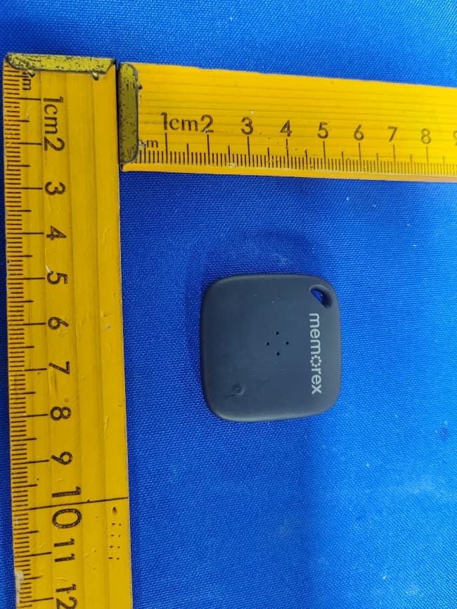
OKUBS6207S
Sep 01, 2026Smart Finder
Equipment Class
DTS - Digital Transmission System
OKUBS2708EC
May 15, 2026STEREO
Equipment Class
DSS - Part 15 Spread Spectrum Transmitter
OKUJC9021
Apr 27, 2026BLUETOOTH TURNTABLE
Equipment Class
DSS - Part 15 Spread Spectrum Transmitter
OKUBS2708CA
Apr 17, 2026STEREO
Equipment Class
DSS - Part 15 Spread Spectrum Transmitter