OKUCHT93932 INCH STEREO SOUND BAR with Bluetooth Wireless Technology
Shenzhen Junlan Electronic Ltd
Click to zoom
Application Details
- Equipment Class
- DXX - Part 15 Low Power Communication Device Transmitter
- Date of Grant
- Nov 28, 2014
- Application Purpose
- Original Equipment
- Date of Application
- Nov 28, 2014
- Equipment Note
- 32 INCH STEREO SOUND BAR with Bluetooth Wireless Technology
- Frequency Range
- 2402.00000000 - 2480.00000000
- Country
- China
Documents & Files
Document Text
Text extracted from the exhibit documents filed with the FCC. Open a document above to read the original.
Users Manual
Owner's Manual PLEASE READ BEFORE OPERATING THIS EQUIPMENT. with Bluetooth ® Wireless Technology with Bluetooth ® Wireless Technology IB Size: 105.5 x 210mm (A5) 32 INCH 32 INCH STEREO SOUND BAR STEREO SOUND BAR Model:CHT939 WARNING:Changes or modifications to this unit not expressly approved by the party responsible for compliance could void the user’s authority to operate the equipment. NOTE: This equipment has been tested and found to comply with the limits for a Class B digital device, pursuant to Part 15 of the FCC Rules. These limits are designed to provide reasonable protection against harmful interference in a residential installation. This equipment generates, uses, and can radiate radio frequency energy and, if not installed and used in accordance with the instructions, may cause harmful interference to radio communications. However, there is no guarantee that interference will not occur in a particular installation. If this equipment does cause harmful interference to radio or television reception, which can be determined by turning the equipment off and on, the user is encouraged to try to correct the interference by one or more of the following measures: • Reorient or relocate the receiving antenna. Increase the separation between the equipment and receiver. Connect the equipment into an outlet on a circuit different from that to which the receiver is connected. Consult the dealer or an experienced radio/TV technician for help. • • • FCC Warnings FCC NOTICE: To assure continued compliance, follow the attached installation instructions and use only shielded cables when connecting to other devices. Modifications not authorized by the manufacturer may void user’s authority to operate this device. This device complies with Part 15 of the FCC rules. Operation is subject to the following two conditions: 1) this device may not cause harmful interference, and 2) this device must accept any interference received, including interference that may cause undesired operation. 2. Mounting the Speaker Bar onto a wall We recommend having this speaker professionally mounted. By using the included wall mounting accessories, the sound bar can be mounted onto a wall. Distance Between Two Brackets 1. Placing on the table When placing the Sound Bar on an entertainment center, bookshelf, or any type of enclosed space, be sure to allow at least 2-3 inches of space around the Sound Bar for ventilation. If the Sound Bar is enclosed in a tight space, without ventilation, heat generated from the Sound Bar could produce a potential heat hazard. To the DC IN jack on the top of the unit. 22.4 inches To the wall outlet NOTE: If Long period of time will not use the unit, unplug the AC Cord from the wall outlet. 1. Insert the plug from the supplied AC/DC adaptor to the DC In Jack on the top of unit. 2. Insert the small plug from the supplied AC Power Cord to the AC In Jack on the AC/DC Adaptor. 3. Insert the AC Plug from the supplied to the wall outlet Having AC 100-240V~; 50/60Hz. To the AC In Jack 1. Mark the position of the mounting screws on the wall using a pencil. 2. Drill the supplied screws directly into the marks that you have made on the wall and leave approx. 0.3 inch length to hook the sound bar. 3. Put the sound bar onto the mounting screws. Make sure they are firm and stable. 4 You may use 2 pieces plastic inserts (Included) 2 pieces screws (Included) 1. Mark the position of the mounting screws on the wall using a pencil. 3. Insert the supplied plastic inserts into the holes by hammer . 5. Put the sound bar onto the mounting screws. Make sure they are firm and stable. (1) (2) 4. Secure the supplied screws into the plastic insert and leave approx. 0.3 inch 2 pieces screws (Included) 2.2 Mounting on the wooden wall: You may use 2.2 Mounting on the wall 2.1 Mounting on the wooden wall length to hook the sound bar. ( Not Supplied ) 2. Drill 2 x 7/32 inch diameter holes by a powerful electric drill ( Not Supplied ). 22.4 inches 22.4 inches OPTICAL AUX IN 2 L R AUX IN 1 FM ANT POWER/ SOURCE VOL- VOL+ PLAY/ PAUSE TUNE-TUNE+ 5 2.Remote sensor 3. Speakers 1. Indicator 3. Speakers Front View POWER/ SOURCE VOL- VOL+ PLAY/ PAUSE FM ANT AUX IN1 AUX IN2 L R 234567891011 2. FM ANT ( FM Antenna ) 3. AUX IN 1 jack 4. AUX IN 2 jacks 5. DC IN jack 6. POWER/SOURCE button 7. VOL- ( Volume Down ) button 8. VOL+ ( Volume Up ) button 9. PLAY/PAUSE button 10. TUNE-/ ( Skip Backward ) button TUNE- TUNE+ 11. TUNE+/ ( Skip Forward ) button Top View OPTICAL 1 1. OPTICAL (Optical In Jack) DC IN DC 16V, 1.8A DC IN DC 16V, 1.8A EQ SOURCE BASS - BASS+ VOL- VOL+ MO/ST TREBLE- TREBLE+ 6 In Standby mode, press and hold to enter to time set mode. 14.SOURCE(mode) Press repeatedly to select the input source to FM; LINE; AUX or BT. 1 2 3 4 5 6 7 8 9 10 11 TUNE- TUNE+ 2. TUNE-/ ( Skip Backward ) button 3. TUNE+/ ( Skip Forward ) button 1. Power ON/OFF button 4. MO/ST ( Mono/Stereo ) button 5. SOURCE button 6. BASS +/- buttons 7. ( Mute ) button 8. EQ ( Equalizer ) button 9. ( Play/Pause ) button 10. VOL ( Volume ) +/- buttons 11. TREBLE +/- buttons 7 BATTERY PRECAUTIONS Fig.1Fig.2 Fig.3 - First Time Use Remove and discard the insulation tab as figure on the right. 1. Push and slide out the battery holder as figure 1 below. 3. Close the battery holder. 2. Replace the battery with a new CR2025 button cell as the polarity markings on the rear of the Remote Control. ° Remote Sensor 30 ° 30 8. This product contains a coin/button cell battery. If the coin/button cell battery is swallowed, it can cause severe internal burn in just 2 hours and can lead to death. Keep new and used batteries away from children. If the battery compartment does not close securely, stop using the product and keep it away from children. If you think batteries might have been swallowed or placed inside any part of the body, seek immediate medical attention. - If the battery is consume, replace it as below: Folloe these precautions when using a battery in this device:…
Text truncated - open the document above for the full version.
ID Label/Location Info
32 INCH STEREO SOUND BAR with Bluetooth ® Wireless Technology
ID Label/Location Info
Label location
RF Exposure Info
FCC ID: OKUCHT939 According to 447498 D01 General RF Exposure Guidance v05 The 1-g and 10-g SAR test exclusion thresholds for 100 MHz to 6 GHz at test separation distances ≤ 50 mm are determined by: [(max. power of channel, including tune-up tolerance, mW)/(min. test separation distance, mm)] ·[√f(GHz)] ≤ 3.0 for 1-g SAR and ≤ 7.5 for 10-g extremity SAR, where --f(GHz) is the RF channel transmit frequency in GHz --Power and distance are rounded to the nearest mW and mm before calculation --The result is rounded to one decimal place for comparison eirp = pt x gt = (EXd) 2 /30 where: pt = transmitter output power in watts, gt = numeric gain of the transmitting antenna (unitless), E = electric field strength in V/m, --- 10 ((dBuV/m)/20) /10 6 d = measurement distance in meters (m) ---3m So pt = (EXd) 2 /30 x gt Field strength = 96.70dBuV/m @3m Ant gain =2dBi, so Ant numeric gain= 1.58 So pt={ [10 (96.70) /10 6 x 3] 2 /30x1.58 }x1000 mW = 0.885mW So (0.885 mW /5mm)x √2.48 = 0.279<3 Then SAR evaluation is not required
Test Report
Global United Technology Services Co., Ltd. Report No.: GTSE14100175801 Authorized Signature: Robinson Lo Laboratory Manager This report details the results of the testing carried out on one sample. The results contained in this test report do not relate to other samples of the same product and does not permit the use of the GTS product certification mark. The manufacturer should ensure that all products in series production are in conformity with the product sample detailed in this report. This report may only be reproduced and distributed in full. If the product in this report is used in any configuration other than that detailed in the report, the manufacturer must ensure the new system complies with all relevant standards. Any mention of GTS or testing done by GTS in connection with, distribution or use of the product described in this report must be approved by GTS in writing. This document cannot be reproduced except in full, without prior written approval of the Company. Any unauthorized alteration, forgery or falsification of the content or appearance of this document is unlawful and offenders may be prosecuted to the fullest extent of the law. Unless otherwise stated the results shown in this test report refer only to the sample(s) tested and such sample(s) are retained for 90 days only. FCC REPORT Applicant: SHENZHEN JUNLAN ELECTRONIC LTD Address of Applicant: District 2 type A plant in the second layer 1-4, NO.2 Industrial Fuyuan Tangwei Fuyong Baoan Shenzhen China Equipment Under Test (EUT) Product Name: 32 INCH STEREO SOUND BAR with Bluetooth ® Wireless Technology Model No.: SBB-25608, CHT939 Trade Mark: Criag FCC ID: OKUCHT939 Applicable standards: FCC CFR Title 47 Part 15 Subpart C Section 15.249:2013 Date of sample receipt: October 26, 2014 Date of Test: November 11-12, 2014 Date of report issued: November 12, 2014 Test Result : PASS * * In the configuration tested, the EUT complied with the standards specified above. Report No.: GTSE14100175801 Global United Technology Services Co., Ltd. Project No.: GTSE141001758RF 2nd Floor, Block No.2, Laodong Industrial Zone, Xixiang Road Baoan District, Shenzhen, China 518102 Telephone: +86 (0) 755 2779 8480 Fax: +86 (0) 755 2779 8960 Page 2 of 30 2 Version Version No. Date Description 00 November 12, 2014 Original Prepared By: Date: November 12, 2014 Project Engineer Check By: Date: November 12, 2014 Reviewer Report No.: GTSE14100175801 Global United Technology Services Co., Ltd. Project No.: GTSE141001758RF 2nd Floor, Block No.2, Laodong Industrial Zone, Xixiang Road Baoan District, Shenzhen, China 518102 Telephone: +86 (0) 755 2779 8480 Fax: +86 (0) 755 2779 8960 Page 3 of 30 3 Contents Page 1 COVER PAGE ............................................................................................................................................ 1 2 VERSION .................................................................................................................................................. 2 3 CONTENTS .............................................................................................................................................. 3 4 TEST SUMMARY ..................................................................................................................................... 4 5 GENERAL INFORMATION ...................................................................................................................... 5 5.1 CLIENT INFORMATION ......................................................................................................................... 5 5.2 GENERAL DESCRIPTION OF EUT ......................................................................................................... 5 5.3 TEST MODE ........................................................................................................................................ 7 5.4 DESCRIPTION OF SUPPORT UNITS ....................................................................................................... 7 5.5 TEST FACILITY .................................................................................................................................... 7 5.6 TEST LOCATION ................................................................................................................................. 7 5.7 OTHER INFORMATION REQUESTED BY THE CUSTOMER ......................................................................... 7 6 TEST INSTRUMENTS LIST ..................................................................................................................... 8 7 TEST RESULTS AND MEASUREMENT DATA ...................................................................................... 9 7.1 ANTENNA REQUIREMENT ..................................................................................................................... 9 7.2 CONDUCTED EMISSIONS ................................................................................................................... 10 7.3 RADIATED EMISSION METHOD ........................................................................................................... 13 7.3.1 Field Strength of The Fundamental Signal ................................................................................ 15 7.3.2 Spurious emissions .................................................................................................................... 16 7.3.3 Bandedge emissions.................................................................................................................. 20 7.4 20DB OCCUPY BANDWIDTH .............................................................................................................. 21 8 TEST SETUP PHOTO ............................................................................................................................ 23 9 EUT CONSTRUCTIONAL DETAILS ..................................................................................................... …
Text truncated - open the document above for the full version.
Test Setup Photos
Radiated Emission Conducted Emissions
Contact Information
Applicant
peng xiao(safety engineer)
Test Firm
Global United Technology Service Co., LtdRobinson Lo
Technical Specifications
| # | Rule Parts | Frequency Range | Power Output |
|---|---|---|---|
| 1 | 15C | 2.40 GHz - 2.48 GHz | - |
Other Applications from Shenzhen Junlan Electronic Ltd
OKUJP2326
Sep 07, 2026Retro Bluetooth Turntable
Equipment Class
DSS - Part 15 Spread Spectrum Transmitter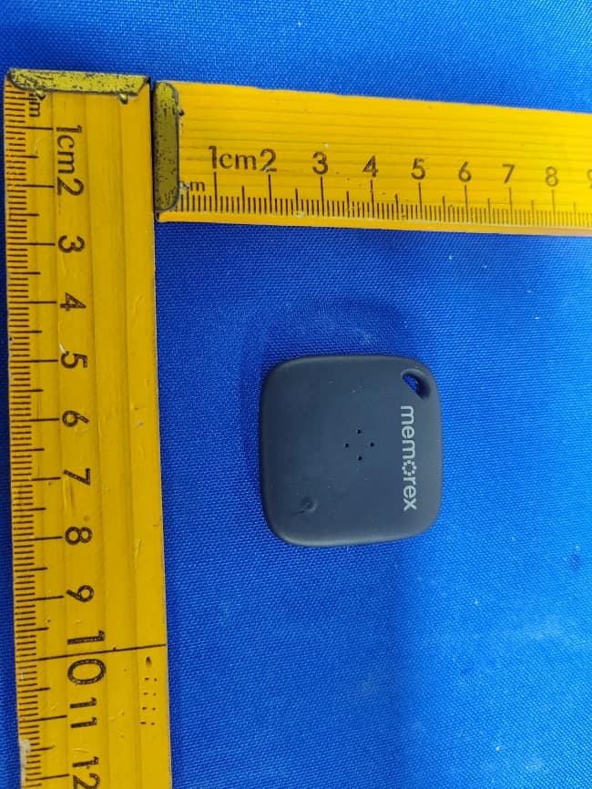
OKUBS6207S
Sep 01, 2026Smart Finder
Equipment Class
DTS - Digital Transmission System
OKUBS2708EC
May 15, 2026STEREO
Equipment Class
DSS - Part 15 Spread Spectrum Transmitter
OKUJC9021
Apr 27, 2026BLUETOOTH TURNTABLE
Equipment Class
DSS - Part 15 Spread Spectrum Transmitter
OKUBS2708CA
Apr 17, 2026STEREO
Equipment Class
DSS - Part 15 Spread Spectrum Transmitter