OKUITB133BBluetooth Tower Speaker with PLL FM Radio
Shenzhen Junlan Electronic Ltd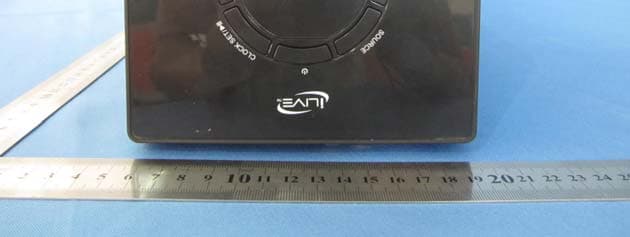
Click to zoom
Application Details
- Equipment Class
- DTS - Digital Transmission System
- Date of Grant
- Jul 31, 2013
- Application Purpose
- Original Equipment
- Date of Application
- Jul 31, 2013
- Equipment Note
- Bluetooth Tower Speaker with PLL FM Radio
- Frequency Range
- 2402.00000000 - 2480.00000000
- Country
- China
Documents & Files
Document Text
Text extracted from the exhibit documents filed with the FCC. Open a document above to read the original.
Users Manual
USER’S GUIDE V: 811-02 For the most up-to-date version of this User’s Guide, go to www.iLiveElectronics.com ITB133B 32” Bluetooth Tower Speaker 2 CAUTION: TO PREVENT ELECTRIC SHOCK, MATCH WIDE BLADE OF PLUG TO WIDE SLOT, FULLY INSERT. WARNING: To reduce the risk of fire or electric shock, do not expose this apparatus to rain or moisture. AVERTISSEMENT: Pour réduire le risque d’incendie ou de choc électrique, ne pas exposer cet appareil sous la pluie et l’humidité. CAUTION: Use of any controls or adjustments or performance of procedures other than those herein specified may result in hazardous radiation exposure. WARNING: Changes or modifications to this unit not expressly approved by the party responsible for compliance could void the user’s authority to operate the equipment. WARNING: Do not place this unit directly onto furniture surfaces with any type of soft, porous, or sensitive finish. As with any rubber compound made with oils, the feet could cause marks or staining where the feet reside. We recommend using a protective barrier such as a cloth or a piece of glass between the unit and the surface to reduce the risk of damage and/or staining. WARNING: Use of this unit near fluorescent lighting may cause interference regarding use of the remote. If the unit is displaying erratic behavior move away from any fluorescent lighting, as it may be the cause. CAUTION: Danger of explosion if battery is incorrectly replaced. Replace only with the same or equivalent type. PRÉCAUTION: Danger d’explosion si les piles sont remplacées de façon incorrect. Remplacer les piles seulement par le même type de pile ou l’équivalent. WARNING: The battery, batteries, and battery pack shall not be exposed to excessive heat such as sunshine, fire, or the like. WARNING: Lithium batteries, like all rechargeable batteries are recyclable and should be recycled or disposed of in normal household waste. Contact your local government for disposal or recycling practices in your area. They should never be incinerated since they might explode. WARNING: Shock hazard - Do Not Open. AVIS: RISQUE DE CHOC ÉLECTRIQUE - NE PAS OUVRIR Mains Plug or Direct plug-in adapter is used as disconnect device and it should remain readily operable during intended use. In order to disconnect the apparatus from the mains completely, the Mains Plug or Direct plug-in adapter should be disconnected from the mains socket outlet completely. La fiche d’alimentation ou adaptateur de courant est utilisé comme dispositif de déconnexion et doit rester accessible pendant l’utilisation. Pour mettre l’appareil hors tension, la fiche ou adaptateur de courant doit être débranché de la prise de courant. The lightning flash with arrowhead symbol, within an equilateral triangle, is intended to alert the user to the presence of uninsulated "dangerous voltage" within the product's enclosure that may be of sufficient magnitude to constitute a risk of electric shock to persons. WARNING: TO REDUCE THE RISK OF ELECTRIC SHOCK, DO NOT REMOVE COVER (OR BACK). NO USER- SERVICEABLE PARTS INSIDE. REFER SERVICING TO QUALIFIED SERVICE PERSONNEL. ATTENTION RISQUE D' ÉLECTROCUTION NE PAS OUVRIR CAUTION RISK OF ELECTRIC SHOCK DO NOT OPEN The exclamation point within an equilateral triangle is intended to alert the user to the presence of important operating and maintenance (servicing) instructions in the literature accompanying the appliance. Warnings and Precautions Customer Support: 1-888-999-42153 13. Unplug this apparatus during lightning storms or when unused for long periods of time. 14. Refer all servicing to qualified service personnel. Servicing is required when the apparatus has been damaged in any way, such as power-supply cord or plug is damaged, liquid has been spilled or objects have fallen into the apparatus, the apparatus has been exposed to rain or moisture, does not operate normally, or has been dropped. 1. Read these Instructions. 2. Keep these Instructions. 3. Heed all Warnings. 4. Follow all instructions. 5. Do not use this apparatus near water. 6. Clean only with a dry cloth. 7. Do not block any ventilation openings. Install in accordance with the manufacturer’s instructions. 8. Do not install near any heat sources such as radiators, heat registers, stoves, or other apparatus (including amplifiers) that produce heat. 9. Do not defeat the safety purpose of the polarized or grounding - type plug. A polarized plug has two blades with one wider than the other. A grounding type plug has two blades and a third grounding prong. The wide blade or the third prong are provided for your safety. When the provided plug does not fit into your outlet, consult an electrician for replacement of the obsolete outlet. 10. Protect the power cord from being walked on or pinched particularly at plugs, convenience receptacles, and the point where they exit from the apparatus. 11. Only use attachments/accessories specified by the manufacturer. 12. This symbol indicates that this product incorporates double insulation between hazardous mains voltage and user accessible parts. Use only with a cart, stand, tripod, bracket, or table specified by the manufacturer, or sold with the apparatus. When a cart is used, use caution when moving the cart/apparatus combination to avoid injury from tip-over. Important Safety Instructions Special note: When placing your unit on a lacquered or natural finish, protect your furniture with a cloth or other protective material. WARNING: Changes or modifications to this unit not expressly approved by the party responsible for compliance could void the user’s authority to operate the equipment. NOTE: This equipment has been tested and found to comply with the limits for a Class B digital device, pursuant to Part 15 of the FCC Rules. These limits are designed to provide reasonable protection against harmful interference in a residential installation. This equipment generates, uses, and can radiate radio frequency energy and, if not installed and used in…
Text truncated - open the document above for the full version.
Attestation Statements
Differences Declaration To whom concern, We Shenzhen Junlan Electronic Ltd hereby declares: The product model(s) TSB-981J2, TSB-981J3, ITB123B are identical in the same PCB layout, interior structure and electrical circuits with the model ITB133B which tested in Global United Technology Services Co., Ltd., the only differences are the model name for commercial purpose. Authorized signature: Date: 2013-07-19
Cover Letter(s)
Shenzhen Junlan Electronic Ltd Date (dd/mm/yyyy) 19/07/2013 BABT TCB Forsyth House, Churchfield Road, Walton-on-Thames, Surrey, KT12 2TD Confidentiality Request FCC ID: OKUITB133B Pursuant to Sections 0.457(d)(1)(ii) and 0.459 of the Commission’s Rules, Shenzhen Junlan Electronic Ltd hereby requests permanent confidential treatment of information accompanying this application as outlined below: Schematics Block Diagrams Theory of Operation The above materials contain trade secrets and proprietary information not customarily released to the public. The public disclosure of these matters might be harmful to the Applicant and provide unjustified benefits to its competitors. The Applicant understands that pursuant to Rule 0.457(d)(1)(ii), disclosure of this Application and all accompanying materials will not be made before the date of the Grant for this Application. Yours sincerely, Company Officer: safety engineer / Peng Xiao Telephone Number: 0755-27309169 Email: [email protected]
ID Label/Location Info
Label location
RF Exposure Info
Global United Technology Services Co., Ltd. Global United Technology Services Co., Ltd. 2nd Floor, Block No.2, Laodong Industrial Zone, Xixiang Road Baoan District, Shenzhen, China 518102 Telephone: +86 (0) 755 2779 8480 Fax: +86 (0) 755 2779 8960 Page 1 of 1 FCC ID:OKUITB133B The device has a standalone transmission. According to KDB 447498 section 4.3.1, the 1-g SAR test exclusion thresholds at test separation distances≤ 50 mm are determined by: [(max. power of channel, including tune-up tolerance, mW)/(min. test separation distance, mm)]·[√f(GHz)] ≤ 3.0 The maximum tune-up limit power is 0.259mW @ 2.441GHz For the head and body SAR, use 5mm as the conservative minimum test separation distance, [(max. power of channel, including tune-up tolerance, mW)/(min. test separation distance, mm)]·[√f(GHz)] =0.081≤ 3.0 So standalone SAR measurements are not required for both head and body.
Test Report
Global United Technology Services Co., Ltd. Report No.: GTSE13060097001 Authorized Signature: Robinson Lo Laboratory Manager This report details the results of the testing carried out on one sample. The results contained in this test report do not relate to other samples of the same product and does not permit the use of the GTS product certification mark. The manufacturer should ensure that all products in series production are in conformity with the product sample detailed in this report. This report may only be reproduced and distributed in full. If the product in this report is used in any configuration other than that detailed in the report, the manufacturer must ensure the new system complies with all relevant standards. Any mention of GTS International Electrical Approvals or testing done by GTS International Electrical Approvals in connection with, distribution or use of the product described in this report must be approved by GTS International Electrical Approvals in writing. This document cannot be reproduced except in full, without prior written approval of the Company. Any unauthorized alteration, forgery or falsification of the content or appearance of this document is unlawful and offenders may be prosecuted to the fullest extent of the law. Unless otherwise stated the results shown in this test report refer only to the sample(s) tested and such sample(s) are retained for 90 days only.” FCC REPORT Applicant: Shenzhen Junlan Electronic Ltd Address of Applicant: District 2 type A plant in the second layer 1-4, NO.2 Industrial Fuyuan Tangwei Fuyong Baoan Shenzhen China Equipment Under Test (EUT) Product Name: BLUETOOTH TOWER SPEAKER WITH PLL FM RADIO Model No.: TSB-981J2, TSB-981J3, ITB133B, ITB123B Trade Mark: ILIVE FCC ID: OKUITB133B Applicable standards: FCC CFR Title 47 Part 15 Subpart C Section 15.249:2012 Date of sample receipt: June 27, 2013 Date of Test: June 27-July 08, 2013 Date of report issued: July 08, 2013 Test Result : PASS * * In the configuration tested, the EUT complied with the standards specified above. Report No.: GTSE13060097001 Global United Technology Services Co., Ltd. Project No.: GTSE130600970RF 2nd Floor, Block No.2, Laodong Industrial Zone, Xixiang Road Baoan District, Shenzhen, China 518102 Telephone: +86 (0) 755 2779 8480 Fax: +86 (0) 755 2779 8960 Page 2 of 33 2 Version Version No. Date Description 00 July 08, 2013 Original Prepared By: Date: July 08, 2013 Project Engineer Check By: Date: July 08, 2013 Reviewer Report No.: GTSE13060097001 Global United Technology Services Co., Ltd. Project No.: GTSE130600970RF 2nd Floor, Block No.2, Laodong Industrial Zone, Xixiang Road Baoan District, Shenzhen, China 518102 Telephone: +86 (0) 755 2779 8480 Fax: +86 (0) 755 2779 8960 Page 3 of 33 3 Contents Page 1 COVER PAGE............................................................................................................................................ 1 2 VERSION .................................................................................................................................................. 2 3 CONTENTS .............................................................................................................................................. 3 4 TEST SUMMARY ..................................................................................................................................... 4 5 GENERAL INFORMATION ...................................................................................................................... 5 5.1 CLIENT INFORMATION......................................................................................................................... 5 5.2 GENERAL DESCRIPTION OF EUT ......................................................................................................... 5 5.3 TEST MODE........................................................................................................................................ 7 5.4 DESCRIPTION OF SUPPORT UNITS....................................................................................................... 7 5.5 TEST FACILITY.................................................................................................................................... 7 5.6 TEST LOCATION................................................................................................................................. 7 5.7 OTHER INFORMATION REQUESTED BY THE CUSTOMER......................................................................... 7 6 TEST INSTRUMENTS LIST ..................................................................................................................... 8 7 TEST RESULTS AND MEASUREMENT DATA...................................................................................... 9 7.1 ANTENNA REQUIREMENT:.................................................................................................................... 9 7.2 CONDUCTED EMISSIONS................................................................................................................... 10 7.3 RADIATED EMISSION METHOD........................................................................................................... 13 7.3.1 Field Strength of The Fundamental Signal ................................................................................ 15 7.3.2 Spurious emissions.................................................................................................................... 16 7.3.3 Bandedge emissions.................................................................................................................. 20 7.4 20DB OCCUPY BANDWIDTH.............................................................................................................. 21 8 TEST SETUP PHOTO ............................................................................................................................ 23 9 EUT CONSTRUCTIONAL DETAILS .........................…
Text truncated - open the document above for the full version.
Test Setup Photos
Radiated Emission Conducted Emission
Contact Information
Applicant
peng xiao(safety engineer)
Test Firm
Global United Technology Service Co., LtdRobinson Lo
Technical Specifications
| # | Rule Parts | Frequency Range | Power Output |
|---|---|---|---|
| 1 | 15C | 2.40 GHz - 2.48 GHz | 259.00 µW |
Other Applications from Shenzhen Junlan Electronic Ltd
OKUJP2326
Sep 07, 2026Retro Bluetooth Turntable
Equipment Class
DSS - Part 15 Spread Spectrum Transmitter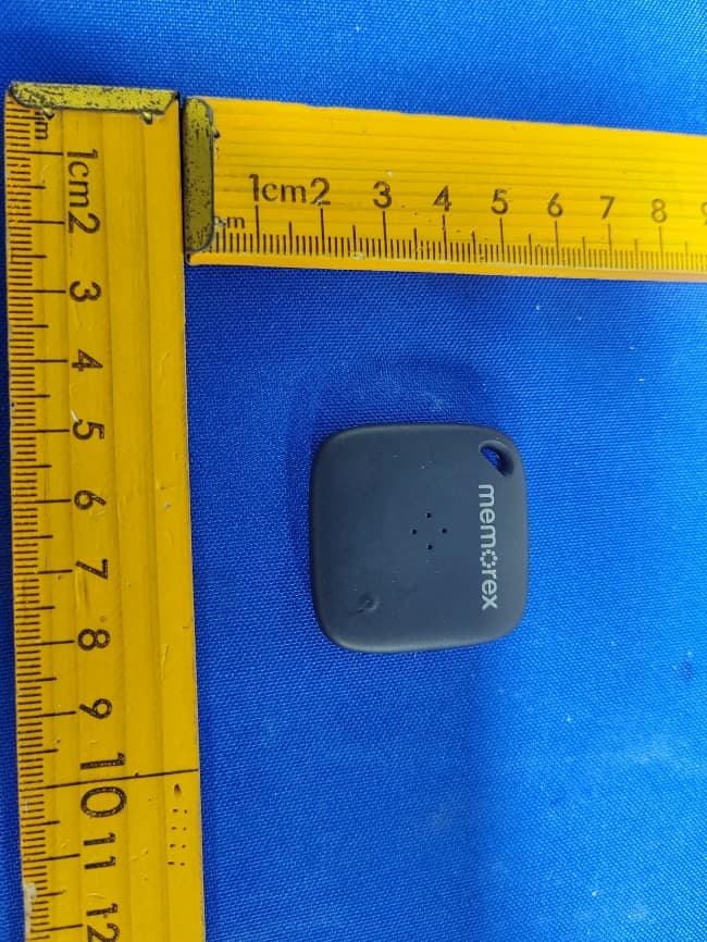
OKUBS6207S
Sep 01, 2026Smart Finder
Equipment Class
DTS - Digital Transmission System
OKUBS2708EC
May 15, 2026STEREO
Equipment Class
DSS - Part 15 Spread Spectrum Transmitter
OKUJC9021
Apr 27, 2026BLUETOOTH TURNTABLE
Equipment Class
DSS - Part 15 Spread Spectrum Transmitter
OKUBS2708CA
Apr 17, 2026STEREO
Equipment Class
DSS - Part 15 Spread Spectrum Transmitter