OKUSB73AGA037 INCH BLUETOOTH 2.1 SOUND BAR - LED ACCENT LIGHTING
Shenzhen Junlan Electronic Ltd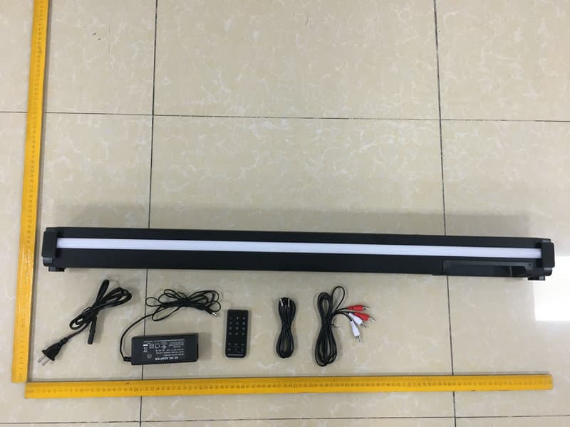
Click to zoom
Application Details
- Equipment Class
- DSS - Part 15 Spread Spectrum Transmitter
- Date of Grant
- Jun 15, 2020
- Application Purpose
- Original Equipment
- Date of Application
- Jun 15, 2020
- Equipment Note
- 37 INCH BLUETOOTH 2.1 SOUND BAR - LED ACCENT LIGHTING
- Frequency Range
- 2402.00000000 - 2480.00000000
- Country
- China
Documents & Files
Document Text
Text extracted from the exhibit documents filed with the FCC. Open a document above to read the original.
Users Manual
Please read this instruction manual carefully and keep it for future reference MODEL:MSB3786 HOME THEATER BLUETOOTH SOUNDBAR WITH LIGHT SHOW AND LED ROOM ILLUMINATION W ARNING:TO PREVENT FIRE OR SHOCK HAZARD, DO NOT EXPOSE THIS UNIT TO RAIN OR MOISTURE. WARNING: USE UNDER SUPERVISION OF AN ADULT DUE TO LONG CORDThis unit has a long cord that can be easily tripped on or pulled on, causing injury. Please make sure it is arranged so that it will not drape over a tabletop, etc. Where it can be pulled on by children or tripped over accidentally. FCC STATEMENT: This device complies with part 15 of the FCC Rules. Operation is subject to the following two conditions: (1)This device may not cause harmful interference, and (2)This device must accept any interference received, including interference that may cause undesired operation. The antenna(s) used for this transmitter must be installed to provide a separation distance of at least 20 cm from all persons and must not be co-located or operating in conjunction with any other antenna or transmitter. CAUTION: TO REDUCE THE ELECTRIC SHOCK, DO NOT REMOVE THE COVER (OR BACK). NO USER SERVICEABLE PART INSIDE, REFER SERVICING TO QUALIFIED SERVICE PERSONNEL. CAUTION RISK OF ELECTRIC SHOCK DO NOT OPEN DANGEROUSVOLTAGE:Thelightingflashwitharrowheadsymbolwithin anequilateraltriangleisintendedtoalerttheusertothepresenceof uninsulated“dangerousvoltage”withintheproduct’senclosurethatmay beof sufficient magnitude to constitute a risk of electric shock to persons. ATTENTION:Theexclamationpointwithinanequilateraltriangleisintendedto alerttheusertothepresenceofimportantoperatingandmaintenance (servicing)instructionsintheliteratureaccompanyingtheappliance. 2 CALIFORNIA PROP 65 WARNING:”WARNING”This product contains c hemicals known to the State of California to cause birth defects or other reproductive harm. For more information on these regulations and a list of chemicals, log on the following website: http://www.oehha.ca.gov/prop65.html ThisproductmeetsandcomplieswithallFederalregulations. This equipment has been tested and found to comply with the limits for a Class B digital device, pursuant to Part 15 of the FCC Rules. These limits are designed to provide reasonable protection against harmful interference in a residential installation. This equipment generates, uses and can radiate radio frequency energy and, if not installed and used in accordance with the instructions, may cause harmful interference to radio communications. However, there is no guarantee that interference will not occur in a particular installation. If this equipment does cause harmful interference to radio or television reception, which can be determined by turning the equipment off and on, the user is encouraged to try to correct the interference by one or more of the following measures: ●Reorient or relocate the receiving antenna. ●Increase the separation between the equipment and receiver. ●Connect the equipment into an outlet on a circuit different from that to which the receiver is connected. ●Consult the dealer or an experienced radio/TV technician for help. FCC WARNING: To assure continued operation, follow the attached installation instructions and use only shield cables when connecting to other devices. Changes or modifications not expressly approved by the party responsible for compliance could void the user's authority to operate the equipment. Before using the unit, be sure to read all operating instruction carefully, please note that these are general precautions and may not pertain to your unit. For example, this unit may not have the capability to be connected to an outdoor antenna. 1.Readtheseinstructions All the safety and operating instructions should be read before the appliance is operated. 2.Keeptheseinstructions The safety and operating instructions should be kept for future reference. 3.Heedallwarnings All warnings on the appliance and in the operating instructions should be adhered to. 4.Followallinstructions All operation and use instructions should be followed. FCC NOTICE: 5.Donotusethisapparatusnearwater The appliance should not be used near water; for example, near a bath tub, 3 washbowl, kitchen sink, laundry tub, in a wet basement, or near a swimming pool. 6.Cleanonlywithdrycloth The appliance should be cleaned only as recommended by the manufacturer. 7.Donotblockanyventilationopenings.Installinaccordancewiththe manufacturer’s instructions. Slots and openings in the cabinet and in the back or bottom are provided for ventilation, to ensure reliable operation of the product and to protect it from overheating. These openings must not be blocked or covered. The openings should never be blocked by placing the product on a bed, sofa, rug, or similar surface. This product should never be placed near or over a radiator or heat source. This product should not be placed in a built-in installation, such as a bookcase or rack unless proper ventilation is provided or the manufacturer’s instructions have been adhered to. 8. Do not install near any heat sources such as radiators, heat registers, stoves, or other apparatus (including amplifiers) that produce heat. 9. Do not defeat the safety purpose of the polarized or grounding-type plug. A polarized plug has two blades with one wider than the other. A grounding type plug has two blades and a third grounding prong. The wide or the third prong are provided for your safety. If the provided plug does not fit into your outlet, consult an electrician for replacement of the obsolete outlet. 10. Protect the power cord from being walked on or pinched particularly at plugs, convenience receptacles, and the point where they exit from the apparatus. 11. Only use attachments / accessories specified by the manufacturer. 12.Useonlywithacart,stand,tripod,bracket,ortable specifiedbythemanufacturer,orsoldwiththeapparatus. Whenacartisused,usecautionwhenmovingthe cart/apparatuscombinationtoavoidinjury fromtip-over. An appliance and cart combin…
Text truncated - open the document above for the full version.
External Photos
FCC ID: OKUSB73AGA0
ID Label/Location Info
Label Location On EUT Label
Internal Photos
FCC ID: OKUSB73AGA0 ANT
Operational Description
version01 Shenzhen Junlan Electronic Ltd Declaration concerning Antenna Specification It is hereby declared that the product Model No.: MSB3786, MSB3786-EO, SB-73AGA0 FCCID:OKUSB73AGA0 fulfills the requirement in FCC test relating to the antenna type. The device specified above confirms to the FCC recommendations for internal antenna type(s) described below: Model No. of antenna: N/A Type of antenna:PCB Antenna Gain of the antenna: 0 dBi Frequency range: 2402MHz~2480MHz The mounting of the antenna is fixed to the radio module and no other antenna should be used. Company name: Shenzhen Junlan Electronic Ltd Address: No.277 PingKui Road, Shijing Community, Pingshan Street, Pingshan New District, Shenzhen,China City:Shenzhen ZIP / Postal code: Country:China Place:Shenzhen,China Date: 2020-06-12 Signature:
RF Exposure Info
RF EXPOSURE EVALUATION FCC ID: OKUSB73AGA0 According to FCC 1.1310: The criteria listed in the following table shall be used to evaluate the environment impact of human exposure to radio frequency(RF) Radiation as specified in §1.1307(b): Routine SAR evaluation refers to that specifically required by §2.1093, using measurements or computer simulation. When routine SAR evaluation is not required, portable transmitters withoutput power greater than the applicable low threshold require SAR evaluation to qualify for TCB approval. Channel (MHz) Maximum output power (dBm) Tune up tolerance (dBm) Max Tune Up Power (dBm) Distance (mm) Calculation results Limit Operating Mode 2402-0.323 -0.323±10.67750.362 3 BDR+EDR 2441-0.198 -0.198±10.80250.376 3 2480-0.636 -0.636±10.36450.342 3 2402-0.842 -0.842±10.15850.321 3 2441-0.836 -0.836±10.16450.324 3 2480-1.431 -1.431±1-0.43150.285 3 Test Results:PASS.
Test Report
Report No.: 18220WC00046001FCC ID: OKUSB73AGA0Page 1 of 59 Code:AB-RF-05-a FCC TEST REPORT Client Name: Shenzhen Junlan Electronic Ltd Address: No.277 PingKui Road, Shijing Community, Pingshan Street, Pingshan New District, Shenzhen, China Product Name: 37" BLUETOOTH 2.1 SOUND BAR - LED ACCENT LIGHTING Date: Jun. 12, 2020 Shenzhen Anbotek Compliance Laboratory Limited Report No.: 18220WC00046001FCC ID: OKUSB73AGA0Page 2 of 59 Code:AB-RF-05-a Contents 1. General Information ............................................................................................................................................... 5 1.1. Client Information ....................................................................................................................................... 5 1.2. Description of Device (EUT) ..................................................................................................................... 5 1.3. Auxiliary Equipment Used During Test ................................................................................................... 6 1.4. Description of Test Modes ........................................................................................................................ 6 1.5. List of channels ........................................................................................................................................... 7 1.6. Description Of Test Setup ......................................................................................................................... 8 1.7. Test Equipment List .................................................................................................................................... 9 1.8. Measurement Uncertainty ....................................................................................................................... 10 1.9. Description of Test Facility ...................................................................................................................... 10 2. Summary of Test Results ................................................................................................................................... 11 3. Conducted Emission Test ................................................................................................................................... 12 3.1. Test Standard and Limit .......................................................................................................................... 12 3.2. Test Setup .................................................................................................................................................. 12 3.3. Test Procedure .......................................................................................................................................... 12 3.4. Test Data .................................................................................................................................................... 12 4. Radiation Spurious Emission and Band Edge ................................................................................................ 17 4.1. Test Standard and Limit .......................................................................................................................... 17 4.2. Test Setup .................................................................................................................................................. 17 4.3. Test Procedure .......................................................................................................................................... 18 4.4. Test Data .................................................................................................................................................... 19 5. Maximum Peak Output Power Test .................................................................................................................. 27 5.1. Test Standard and Limit .......................................................................................................................... 27 5.2. Test Setup .................................................................................................................................................. 27 5.3. Test Procedure .......................................................................................................................................... 27 5.4. Test Data .................................................................................................................................................... 27 6. 20DB Occupy Bandwidth Test ........................................................................................................................... 31 6.1. Test Standard ............................................................................................................................................ 31 6.2. Test Setup .................................................................................................................................................. 31 6.3. Test Procedure .......................................................................................................................................... 31 6.4. Test Data .................................................................................................................................................... 31 7. Carrier Frequency Separation Test ................................................................................................................... 35 7.1. Test Standard and Limit .......................................................................................................................... 35 7.2. Test Setup .................................................................................................................................................. 35 7.3. Test Procedure .............................................................................................…
Text truncated - open the document above for the full version.
Test Setup Photos
FCC ID: OKUSB73AGA0 Photo of Conducted Emission Measurement Photo of Radiation Emission Test
Contact Information
Applicant
peng xiao(safety engineer)
Test Firm
Shenzhen Anbotek Compliance Laboratory LimitedJeff Zhu
Technical Specifications
| # | Rule Parts | Frequency Range | Power Output |
|---|---|---|---|
| 1 | 15C | 2.40 GHz - 2.48 GHz | 960.00 µW |
Other Applications from Shenzhen Junlan Electronic Ltd
OKUJP2326
Sep 07, 2026Retro Bluetooth Turntable
Equipment Class
DSS - Part 15 Spread Spectrum Transmitter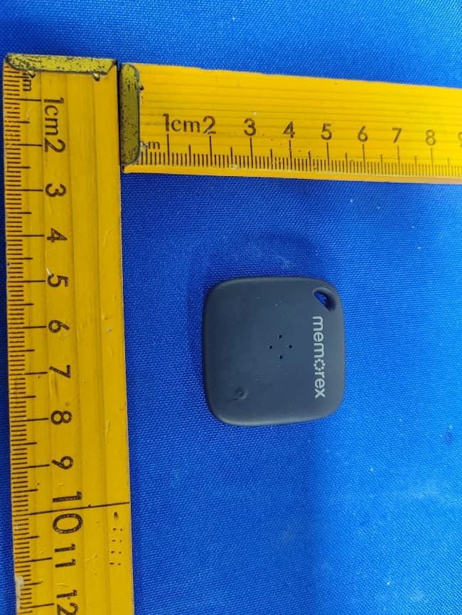
OKUBS6207S
Sep 01, 2026Smart Finder
Equipment Class
DTS - Digital Transmission System
OKUBS2708EC
May 15, 2026STEREO
Equipment Class
DSS - Part 15 Spread Spectrum Transmitter
OKUJC9021
Apr 27, 2026BLUETOOTH TURNTABLE
Equipment Class
DSS - Part 15 Spread Spectrum Transmitter
OKUBS2708CA
Apr 17, 2026STEREO
Equipment Class
DSS - Part 15 Spread Spectrum Transmitter