OKUSBP9015060BLUETOOTH iPAD iTOWER SPEAKER
Shenzhen Junlan Electronic Ltd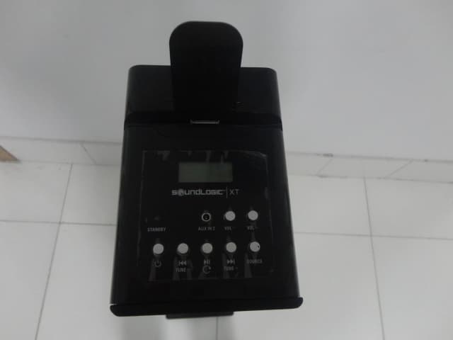
Click to zoom
Application Details
- Equipment Class
- DSS - Part 15 Spread Spectrum Transmitter
- Date of Grant
- Jul 31, 2012
- Application Purpose
- Original Equipment
- Date of Application
- Jul 31, 2012
- Equipment Note
- BLUETOOTH iPAD iTOWER SPEAKER
- Frequency Range
- 2402.00000000 - 2480.00000000
- Country
- China
Documents & Files
Document Text
Text extracted from the exhibit documents filed with the FCC. Open a document above to read the original.
Users Manual
BLUETOOTH iPAD iTOWER SPEAKER Instruction Manual Model: BITS-1/5616 PLEASE READ BEFORE OPERATING THIS EQUIPMENT. TM XT SBI-9015说明书JLE-12239 12012-7-16 17:48:05 1 SBI-9015说明书JLE-12239 12012-7-16 17:48:05 1 W A R N I N G : T O R E D U C E T H E R I S K OF ELECTRIC SHOCK, DO NOT R E M O V E C O V E R ( O R B A C K ) . N O USERSERVICEABLEPARTS INSIDE. REFER S E RV I C I N G TO Q U A L I F I E D S E RV I C E PERSONNEL. The lighting flash with arrowhead symbol, within an equilateral triangle, is intended to alert the user to the presence of uninsulated "dangerous voltage" within the product's enclosure that may be of sufficient magnitude to constitute a risk of electric shock to persons. The exclamation point within an equilateral triangle is intended to alert the user to presence of important o p e r a t i n g a n d m a i n t e n a n c e ( s e r v i c i n g ) instructions in the literature accompanying the appliance. • CAUTION: TO P R E V E N T E L E C T R I C SHOCK, MATCH WIDE BLADE OF PLUG TO WIDE SLOT, FULLY INSERT. • WARNING: To reduce the risk of fire or electric shock, do not expose this apparatus to rain or moisture. • CAUTION: U s e o f a n y c o n t r o l s o r adjustments or performance of procedures other than those herein specified may result in hazardous radiation exposure. • WARNING: Changes or modifications to this unit not expressly approved by the party responsible for compliance could void the user’s authority to operate the equipment. • WARNING: Do not place the unit on top of any soft, porous, or sensitive surfaces to avoid damaging the surface. Use a protective barrier between the unit and surface to protect the surface. • WARNING: Use of this unit near fluorescent lighting may cause interference regarding use of the remote. If the unit is displaying erratic behavior move away from any fluorescent lighting, as it may be the cause. • CAUTION: Danger of explosion if battery is incorrectly replaced. Replace only with the same or equivalent type. • WARNING: This package may contain plastic bags or other materials that pose a hazard to children. Be sure to safely dispose of all packing materials after opening. • WARNING: Shock hazard - Do Not Open. Mains plug is used as disconnect device and it should remain readily operable during intended use. In order to disconnect the apparatus from the mains completely, the mains plug should be disconnected from the mains socket outlet completely. Do not mix old and new batteries. Do not mix alkaline, standard (carbon-zinc), or rechargeable (ni-cad, ni-mh, etc) batteries. Additional Warnings • The apparatus shall not be exposed to dripping or splashing and that no objects filled with liquids, such as vases, shall be placed on apparatus. • Main plug is used as disconnect device and it should remain readily operable during intended use. In order to disconnect the apparatus from the mains completely, the mains plug should be disconnected form the mains socket outlet completely. • Battery shall not be exposed to excessive heat such as sunshine, fire or the like. • Caution marking is located at the rear or back of the apparatus. • The marking information is located at the rear or back of apparatus. This symbol indicates that this p r o d u c t i n c o r p o r a t e s d o u b l e insulation between hazardous mains voltage and user accessible parts. Warnings and Precautions SBI-9015说明书JLE-12239 12012-7-16 17:48:05 2 Important Safety instructions 1. Read these Instructions. 2. Keep these Instructions. 3. Heed all Warnings. 4. Follow all instructions. 5. Do not use this apparatus near water. 6. Clean only with a dry cloth. 7. Do not block any ventilation openings. Install in accordance with the manufacturer’s instructions. 8. Do not install near any heat sources such as radiators, heat registers, stoves, or other apparatus (including amplifiers) that produce heat. 9. Do not defeat the safety purpose of the polarized or grounding - type plug. A polarized plug has two blades with one wider than the other. A grounding type plug has two blades and a third grounding prong. The wide blade or the third prong are provided for your safety. When the provided plug does not fit into your outlet, consult an electrician for replacement of the obsolete outlet. 1 0 . P r o t e c t t h e p o w e r c o r d f r o m b e i n g walked on or pinched particularly at plugs, convenience receptacles, and the point where they exit from the apparatus. 11 . O n l y u s e a t t a c h m e n t s / a c c e s s o r i e s specified by the manufacturer. 12. Use only with a cart, stand, tripod, bracket, or table specified by the manufacturer, or sold with the apparatus. When a cart is used, use caution when moving the cart/apparatus combination to avoid injury from tip-over. 13. Unplug this apparatus during lightning storms or when unused for long periods of time. 14. Refer all servicing to qualified service personnel. Servicing is required when the apparatus has been damaged in any way, such as power- supply cord or plug is damaged, liquid has been spilled or objects have fallen into the apparatus, the apparatus has been exposed to rain or moisture, does not operate normally, or has been dropped. FCC Warnings WARNING: Changes or modifications to this unit not expressly approved by the party responsible for compliance could void the user’s authority to operate the equipment. NOTE: This equipment has been tested and found to comply with the limits for a Class B digital device, pursuant to Part 15 of the FCC Rules. These limits are designed to provide r e a s o n a b l e p r o t e c t i o n a g a i n s t h a r m f u l interference in a residential installation. This equipment generates, uses, and can radiate radio frequency energy and, if not installed and used in accordance with the instructions, may cause harmful interference to radio communications. However, there is no guarantee that interference will not occur in a particular installation. If this equipment does cause harmful inter…
Text truncated - open the document above for the full version.
External Photos
FCC ID: OKUSBP9015060 EST Technology Co.,Ltd Report No.ESTE-R1207001 Page 120 of 125 13. PHOTOS OF EUT External Photos FCC ID: OKUSBP9015060 EST Technology Co.,Ltd Report No.ESTE-R1207001 Page 121 of 125 External Photos FCC ID: OKUSBP9015060 EST Technology Co.,Ltd Report No.ESTE-R1207001 Page 122 of 125 External Photos
ID Label/Location Info
80 × 40 mm 80 × 40 mm
Internal Photos
FCC ID: OKUSBP9015060 EST Technology Co.,Ltd Report No.ESTE-R1207001 Page 123 of 125 Internal Photos FCC ID: OKUSBP9015060 EST Technology Co.,Ltd Report No.ESTE-R1207001 Page 124 of 125 Internal Photos FCC ID: OKUSBP9015060 EST Technology Co.,Ltd Report No.ESTE-R1207001 Page 125 of 125 Internal Photos Antenna
RF Exposure Info
DONGGUAN ALLLIKE ELECTRONIC CO.,LTD ShenZhen Junlan Electronic Ltd BLUETOOTH iPAD iTOWER SPEAKER Model Number: BITS-1/5616 FCC ID: OKUSBP9015060 Prepared for : ShenZhen Junlan Electronic Ltd District 2 type A plant in the second layer 1-4,NO.2 Industrial ,Fuyuan, Tangwei ,Fuyong ,Baoan ,Shenzhen China. Prepared By : EST Technology Co., Ltd. Chilingxiang, Qishantou, Santun, Houjie, Dongguan, Guangdong, China Tel: 86-769-83081888-808 Report Number: ESTE-R1207002 Date of Test : July 4~13, 2012 Date of Report : July 16,2012 Maximum Permissible Exposure 1、Applicable Standard Systems operating under the provisions of this section shall be operated in a manner that ensures that the public is not exposed to radio frequency energy level in excess limit for maximum permissible exposure. In accordance with 47 CFR FCC Part 2 Subpart J, section 2.1091 this device has been defined as a mobile device whereby a distance of 0.2m normally can be maintained between the user and the device. (a)、Limits for Occupational / Controlled Exposure Frequency Range (MHz) Electric Field Strength E) (V/m) Magnetic Field Strength (H) (A/m) Power Density (S) (mW/cm2) Averaging Times︱E︱ 2 , ︱H︱2 or S (minutes) 0.3-3.0 614 1.63 (100)* 6 3.0-30 1842/f 4.89/f (900/f)* 6 30-300 61.4 0.163 1.0 6 300-1500 F/300 6 1500-10000 5 6 (b)、Limits for General Population / Uncontrolled Exposure Frequency Range (MHz) Electric Field Strength E) (V/m) Magnetic Field Strength (H) (A/m) Power Density (S) (mW/cm2) Averaging Times︱E︱ 2 , ︱H︱2 or S (minutes) 0.3-1.34 614 1.63 (100)* 30 1.34-30 824/f 2.19/f (180/f)* 30 30-300 27.5 0.073 0.2 30 300-1500 F/1500 30 1500-10000 1.o 30 Note: f=frequency in MHz; *Plane-wave equivalent power density 2、MPE Calculation Method E (V/m) = (30*P*G) 0.5/d Power Density: Pd (W/m2) = E2/377 E = Electric Field (V/m) P = Peak RF output Power (W) G = EUT Antenna numeric gain (numeric) d = Separation distance between radiator and human body (m) The formula can be changed to Pd = (30*P*G) / (377*d2) From the peak EUT RF output power, the minimum mobile separation distance, d=0.2m, as well as the gain of the used antenna, the RF power density can be obtained 3、Calculated Result and Limit Antenna gain Mode Frequency (MHz) Peak output power (dBm) Peak output power (mW) (dBi) (Linear) Power Density (S) (mW/cm2) Limited of Power Density (S) (mW/cm2) Test Result 2402 2.593 1.8160 1 0.00036 1 Compiles 2441 2.941 1.9680 1 0.00039 1 Compiles GFSK 2480 3.892 2.4500 1 0.00048 1 Compiles 2402 1.750 1.4960 1 0.00029 1 Compiles 2441 2.020 1.5920 1 0.00031 1 Compiles π/4-DQPSK 2480 2.704 1.8630 1 0.00037 1 Compiles 2402 1.898 1.5480 1 0.00030 1 Compiles 2441 2.232 1.6710 1 0.00033 1 Compiles 8-DPSK 2480 3.011 2.0000 1 0.00039 1 Compiles
Test Report
FCC ID: OKUSBP9015060 EST Technology Co.,Ltd Report No.ESTE-R1207001 Page 1 of 125 FCC PART 15C TEST REPORT FOR CERTIFICATION On Behalf of ShenZhen Junlan Electronic Ltd BLUETOOTH iPAD iTOWER SPEAKER Model Number: BITS-1/5616 FCC ID: OKUSBP9015060 Prepared for : SHENZHEN JUNLAN ELECTRONIC LTD District 2 type A plant in the second layer 1-4,NO.2 Industrial ,Fuyuan, Tangwei ,Fuyong ,Baoan ,Shenzhen China. Prepared By : EST Technology Co., Ltd. Santun Management Zone , Houjie District, Dongguan, Guangdong, China Tel: 86-769-83081888-808 Report Number: ESTE-R1207001 Date of Test : July 4~13, 2012 Date of Report : July 16,2012 FCC ID: OKUSBP9015060 EST Technology Co.,Ltd Report No.ESTE-R1207001 Page 2 of 125 TABLE OF CONTENTS Description Page TEST REPORT VERIFICATION.........................................................................................................................3 1. GENERAL INFORMATION.................................................................................................................5 1.1. Description of Device (EUT) ........................................................................................................... 5 2. SUMMARY OF TEST.........................................................................................................................6 2.1. Summary of test result...................................................................................................................... 6 2.2. Test Facilities ................................................................................................................................... 7 2.3. Assistant equipment used for test ..................................................................................................... 8 2.4. Block Diagram ................................................................................................................................. 8 2.5. Test mode ......................................................................................................................................... 8 2.6. Test Equipment................................................................................................................................. 9 3. MAXIMUM PEAK OUTPUT POWER.................................................................................................10 3.1. Limit ............................................................................................................................................... 10 3.2. Test Procedure ................................................................................................................................ 10 3.3. Test Result ...................................................................................................................................... 10 3.4. Test Data ........................................................................................................................................ 11 4. 20 DB BANDWIDTH.......................................................................................................................17 4.1. Limit ............................................................................................................................................... 17 4.2. Test Procedure ................................................................................................................................ 17 4.3. Test Result ...................................................................................................................................... 17 4.4. Test Data ........................................................................................................................................ 18 5. CARRIER FREQUENCY SEPARATION..............................................................................................24 5.1. Limit ............................................................................................................................................... 24 5.2. Test Procedure ................................................................................................................................ 24 5.3. Test Result ...................................................................................................................................... 24 5.4. Test Data ........................................................................................................................................ 25 6. NUMBER OF HOPPING CHANNEL..................................................................................................31 6.1. Limit ............................................................................................................................................... 31 6.2. Test Procedure ................................................................................................................................ 31 6.3. Test Result ...................................................................................................................................... 31 6.4. Test Data ........................................................................................................................................ 32 7. DWELL TIME.................................................................................................................................35 7.1. Limit ............................................................................................................................................... 35 7.2. Test Result ...................................................................................................................................... 35 7.3. Test Data ........................................................................................................................................ 36 8. RADIATED EMISSIONS....................................................................................................................45 8.1. Limit ............…
Text truncated - open the document above for the full version.
Test Setup Photos
FCC ID: OKUSBP9015060 EST Technology Co.,Ltd Report No.ESTE-R1207001 Page 118 of 125 12. TEST SETUP PHOTO Radiated Test (30-1000 MHz) Radiated Test (1000-25000 MHz) FCC ID: OKUSBP9015060 EST Technology Co.,Ltd Report No.ESTE-R1207001 Page 119 of 125 Conducted test
Contact Information
Applicant
peng xiao(safety engineer)
Test Firm
EST Technology Co.,LtdIceman Hu
[email protected]86-769-83081888
Technical Specifications
| # | Rule Parts | Frequency Range | Power Output |
|---|---|---|---|
| 1 | 15C | 2.40 GHz - 2.48 GHz | 2.45 mW |
Other Applications from Shenzhen Junlan Electronic Ltd
OKUJP2326
Sep 07, 2026Retro Bluetooth Turntable
Equipment Class
DSS - Part 15 Spread Spectrum Transmitter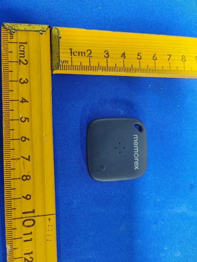
OKUBS6207S
Sep 01, 2026Smart Finder
Equipment Class
DTS - Digital Transmission System
OKUBS2708EC
May 15, 2026STEREO
Equipment Class
DSS - Part 15 Spread Spectrum Transmitter
OKUJC9021
Apr 27, 2026BLUETOOTH TURNTABLE
Equipment Class
DSS - Part 15 Spread Spectrum Transmitter
OKUBS2708CA
Apr 17, 2026STEREO
Equipment Class
DSS - Part 15 Spread Spectrum Transmitter