OKY12115100A01ARFID Card Reader
Baltech AG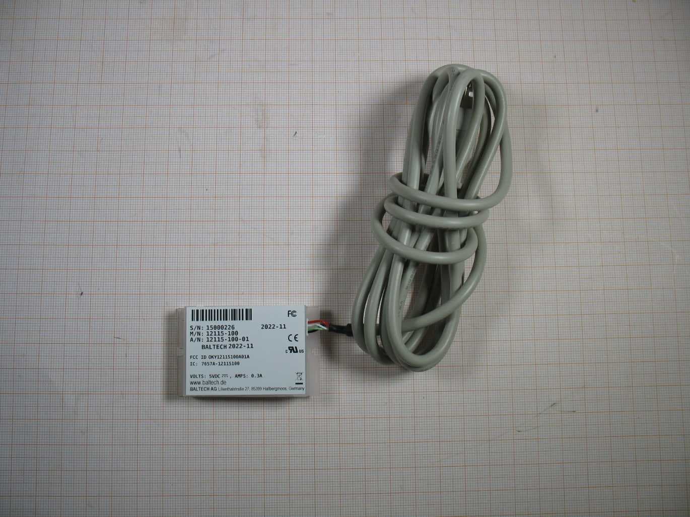
Click to zoom
Application Details
- Equipment Class
- DXX - Part 15 Low Power Communication Device Transmitter
- Date of Grant
- Jan 04, 2023
- Application Purpose
- Original Equipment
- Date of Application
- Jan 04, 2023
- Equipment Note
- RFID Card Reader
- Frequency Range
- 13.56000000 - 13.56000000
- Company
- Baltech AG
- Country
- Germany
Documents & Files
Document Text
Text extracted from the exhibit documents filed with the FCC. Open a document above to read the original.
Users Manual
Operational Manual Rev: 02 Date: 2023-01-04 1 Operation Manual RFID Reader Covered Variants: M/N: 12115-100 REVISION 2.0, 2023-01-04 BALTECH AG Lilienthalstraße 27 85399 Hallbergmoos Germany Phone: +49 (811) 99 88 1- 0 FAX: +49 (811) 99 88 1- 11 e-mail: [email protected] http://www.baltech.de/ Operational Manual Rev: 02 Date: 2023-01-04 2 The “12115-100” Reader/Writer is a desktop contactless smart card USB Smart card reader and writer with the high frequency card technology. It supports Mifare, ISO 14443A/B and ISO 15693 standards transponders. Based on BALTECH’s core technology it provides support of the latest smartcard technologies, encryption and security features. Mounting and Connection The reader generates magnetic field at 13.56MHz which could be influenced by any electrically conductive material close to the device. To ensure good performances and functionalities in terms of read range and reliability a minimum distance of 10cm from such materials is required. Mounting the unit directly to metal would result in a severe reduction of read range down to zero functionality. Care should be taken when testing the device after mounting at a problematic environment: Read ranges and performance vary from card to card and very much from card to tag or key-fob. When mounting multiple readers, the distance between readers should be minimum 0.5 m in order to avoid degradation of performance due to interference. To connect the device to a host system (a printer or a PC), please make sure that the system provides an USB socket intended for connection of the reader. Operation Whenever the device is connected to a proper power supply, it will switch on the internal antenna and periodically scan for a card. Once a card has been detected, the card number is read, the data converted and sent to the host system through the USB Interface. To enable the device to read cards, tags and key-fobs successfully, they should be placed centred above the reader. The device is used for identification, access control. Operational Manual Rev: 02 Date: 2023-01-04 3 Technical Features Operating Frequency • 13.56MHz Data transmission modulation reader to card: ASK Data transmission modulation card to reader: AM/Load modulation Interfaces USB: Full speed 2.0 Contactless Card Supported standards: ISO14443 A & B, ISO15693, Communication speed ISO14443A/B: Baud rate up to 424kBaud Operating Range • ISO14443A/B: up to 5cm • ISO15693: up to 8cm Human Red, Green, Blue LEDs & Buzzer Supply Power [V DC ] +5V (±5%) Power Consumption [W] Up to 1.5 / 1 typ. Operating Temperature [°C] -20 to +65 Operating Humidity [%] 20 to 80 relative humidity; non-condensing Non-Operating Humidity [%] 10 to 90 relative humidity; non-condensing Antennas • 13.56MHz integrates PCB loop antenna Duty cycle for normal use operation [ 6 minutes time window] Use 1 time within 6 minutes. An interaction with the user is 10 seconds in the vicinity to the device. • Duty Cycle = (1 x 10s )/ 6 min = 2,78 % Operational Manual Rev: 02 Date: 2023-01-04 4 Pinning The reader supports USB host interface. USB Interface Molex Header (4 pins) Molex Part Number: 53261-0471 Pin# Name Type Description 1 PWR Power 5V Power Supply 2 D- Data USB-Data inverted 3 D+ Data USB-Data 4 GND Power Signal and Power Ground General regulatory requirements for 12115-100 FCC ID: OKY12115100A01A IC : 7657A-12115100 PMN : RF1060R NOTICE: This device complies with Part 15 of the FCC Rules and with Industry Canada licence-exempt RSS standard(s). Operation is subject to the following two conditions: (1) this device may not cause harmful interference, and (2) this device must accept any interference received, including interference that may cause undesired operation. Le présent appareil est conforme aux CNR d'Industrie Canada applicables aux appareils radio exempts de licence. L'exploitation est autorisée aux deux conditions suivantes: (1) l'appareil ne doit pas produire de brouillage, et (2) l'utilisateur de l'appareil doit accepter tout brouillage radioélectrique subi, même si le brouillage est susceptible d'en compromettre le fonctionnement. Operational Manual Rev: 02 Date: 2023-01-04 5 Changes or modifications made to this equipment not expressly approved by BALTECH AG may void the FCC authorization to operate this equipment. NOTE: This equipment has been tested and found to comply with the limits for a Class B digital device, pursuant to Part 15 of the FCC Rules. These limits are designed to provide reasonable protection against harmful interference in a residential installation. This equipment generates, uses and can radiate radio frequency energy and, if not installed and used in accordance with the instructions, may cause harmful interference to radio communications. However, there is no guarantee that interference will not occur in a particular installation. If this equipment does cause harmful interference to radio or television reception, which can be determined by turning the equipment off and on, the user is encouraged to try to correct the interference by one or more of the following measures: • Reorient or relocate the receiving antenna. • Increase the separation between the equipment and receiver. • Connect the equipment into an outlet on a circuit different from that to which the receiver is connected. • Consult the dealer or an experienced radio/TV technician for help.
External Photos
Annex A 1-5336/22-01-01_AnnexA External photos of the Equipment Under Test This addendum is electronically signed and valid without handwritten signature. For verification of the electronic signatures, the public keys can be requested at the testing laboratory. Document authorized: Tobias Wittenmeier Testing Manager Radio Communications & EMC CTC advanced GmbHUntertuerkheimer Str. 6-10 66117 Saarbruecken / Germany Phone: +49 681 5 98 - 0 Fax: +49 681 5 98 - 9075 web: ctcadvanced.com e-mail: [email protected] Photos Photo 1 Photo 2 2022-11-16Document No. 1-5336/22-01-01_AnnexA2/6 Photo 3 Photo 4 2022-11-16Document No. 1-5336/22-01-01_AnnexA3/6 Photo 5 Photo 6 2022-11-16Document No. 1-5336/22-01-01_AnnexA4/6 Photo 7 2022-11-16Document No. 1-5336/22-01-01_AnnexA5/6 Document history VersionApplied changesDate of release initial release2022-11-16 - END OF DOCUMENT - 2022-11-16Document No. 1-5336/22-01-01_AnnexA6/6
ID Label/Location Info
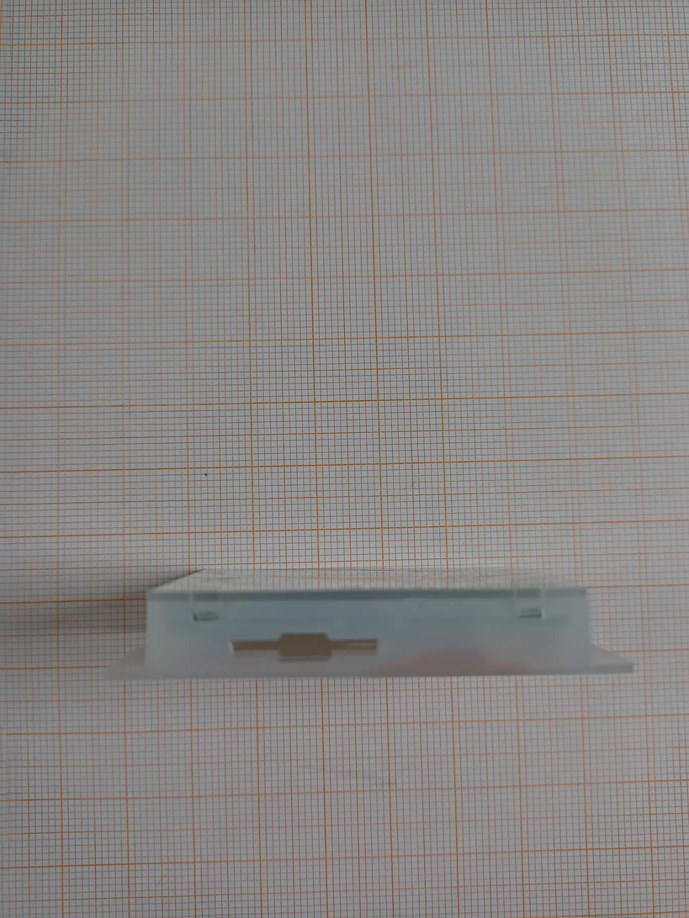
Label Information M/N: 12115-100 FCC ID: OKY12115100A01A IC : 7657A-12115100 M/N : 12115-100
Internal Photos
Annex B 1-5336/22-01-01_AnnexB Internal photos of the Equipment Under Test This addendum is electronically signed and valid without handwritten signature. For verification of the electronic signatures, the public keys can be requested at the testing laboratory. Document authorized: Tobias Wittenmeier Testing Manager Radio Communications & EMC CTC advanced GmbHUntertuerkheimer Str. 6-10 66117 Saarbruecken / Germany Phone: +49 681 5 98 - 0 Fax: +49 681 5 98 - 9075 web: ctcadvanced.com e-mail: [email protected] Photos Photo 1 Photo 2 2022-11-16Document No. 1-5336/22-01-01_AnnexB2/3 Document history VersionApplied changesDate of release initial release2022-11-16 - END OF DOCUMENT - 2022-11-16Document No. 1-5336/22-01-01_AnnexB3/3
RF Exposure Info
BNetzA - CAB - 02/21 - 102 SAR Test exclusion documentation according to FCC KDB 447498 Report identification number: 1-5336/22-01-03 Exclusion (FCC) contains the module with the following certification numbers FCC ID OKY12115100A01A This test report is electronically signed and valid without handwritten signature. For verification of the electronic signatures, the public keys can be requested at the testing laboratory. Document authorised: Alexander Hnatovskiy Marco Scigliano Lab Manager Testing Manager Radio Communications & EMC Radio Communications & EMC Test report no.: 1-5336/22-01-03 © CTC advanced GmbH Page 2 of 3 EUT technologies: Technologies: Max. declared cond. AVG Power Max. measured EIRP Antenna gain NFC 13.56 MHz 18.88 dBm (=77.2mW) 43.3 dBμV (Peak)@30m = -31.95 dBm 1) < 0 dBi NOTE: The measured PEAK EIRP according 2) , proofs that the EUT antenna gain is far below 0dBi and that considering the max. declared output power is by far larger than the EIRP. Conducted values will be used for the RF exposure calculation. EIRP values are for information only. The following table shows the max. declared Peak values and duty corrections for 13.56 MHz: Technology Max. decl. cond. Peak power: [dBm] 3) Duty cycle 2) [%] Max. declared cond. AVG Power [dBm] NFC 13.56 MHz 400 mW 19.3 77.2 mW 1) Test results for EIRP taken from CTC advanced GmbH report 1-5336/22-01-02-A (page 19). 2) The duty cycles can be found in Annex A of this document. 3) Max. output power for the13.56 MHz RFID is 400 mW according customer declaration. SAR test exclusion according to KDB447498 (General RF Exposure Guidance v06) NFC: (c) (2) Standalone SAR test exclusion below 100 MHz < 50mm 0.5 × (Threshold 100MHz ) × (1+log(100/f)) where Threshold 1-g;10-g is 3 for 1-g; 7.5 for 10-g f is the RF channel transmit frequency Threshold 100MHz,50mm is Threshold 1-g;10-g × d / f 0.5 ; with f = 100MHz and d=50mm The table below gives the calculated maximal power that could be used for source based time averaged conducted power, adjusted for tune up tolerance. If this is below the calculated value SAR testing is excluded. frequencyPowerlimit [MHz][mW][dBm][mW] 13.563 474.34442.9718.88 77.3yes Threshold 100MHz,50mm P max-declared ExclusionThreshold1-g;10-g This prediction demonstrates the following: The power density levels for FCC that are larger than the minimum safety-distances stated above, are below the maximum levels allowed by regulations. Test report no.: 1-5336/22-01-03 © CTC advanced GmbH Page 3 of 3 Annex A: Duty cycles Duty cycle 13.56 MHz of the EUT: Duty Cycle 19.3%
Test Report
TEST REPORT Test report no.: 1-5336_22-01-02-A Testing laboratory Applicant CTC advanced GmbH Untertuerkheimer Strasse 6 – 10 66117 Saarbruecken / Germany Phone: + 49 681 5 98 - 0 Fax: + 49 681 5 98 - 9075 Internet: https://www.ctcadvanced.com e-mail: [email protected] Accredited Testing Laboratory: The testing laboratory (area of testing) is accredited according to DIN EN ISO/IEC 17025 (2018-03) by the Deutsche Akkreditierungsstelle GmbH (DAkkS) The accreditation is valid for the scope of testing procedures as stated in the accreditation certificate starting with the registration number: D-PL-12076-01. Baltech AG Lilienthalstrasse 27 85399 Hallbergmoos / GERMANY Phone: ++49 (0)811-99881-0 Contact: Iftekhar Alam e-mail: [email protected] Manufacturer Baltech AG Lilienthalstrasse 27 85399 Hallbergmoos / GERMANY Test standard/s FCC - Title 47 CFR Part 15 FCC - Title 47 of the Code of Federal Regulations; Chapter I; Part 15 - Radio frequency devices RSS - 210 Issue 10 Spectrum Management and Telecommunications Radio Standards Specification - Licence-Exempt Radio Apparatus: Category I Equipment For further applied test standards please refer to section 3 of this test report. Test Item Kind of test item: USB RFID reader Model name: 12115-100 FCC ID: OKY12115100A01A ISED certification number: 7657A-12115100 Frequency: 13.56 MHz Technology tested: RFID Antenna: Integrated antenna Power supply: 4.25 V to 5.75 V DC by USB Temperature range: -25°C to +55°C This test report is electronically signed and valid without handwritten signature. For verification of the electronic signatures, the public keys can be requested at the testing laboratory. Test report authorized: Test performed: p.o. Christoph Schneider Tobias Wittenmeier Lab Manager Testing Manager Radio Communications Radio Communications Test report no.: 1-5336_22-01-02-A © CTC advanced GmbH Page 2 of 31 1 Table of contents 1 Table of contents ............................................................................................................................................ 2 2 General information ....................................................................................................................................... 3 2.1 Notes and disclaimer .......................................................................................................................... 3 2.2 Application details ............................................................................................................................... 3 2.3 Test laboratories sub-contracted ...................................................................................................... 3 3 Test standard/s, references and accreditations .......................................................................................... 4 4 Reporting statements of conformity – decision rule .................................................................................. 5 5 Test environment ............................................................................................................................................ 6 6 Test item .......................................................................................................................................................... 6 6.1 General description ............................................................................................................................. 6 6.2 Additional information ........................................................................................................................ 6 7 Description of the test setup ......................................................................................................................... 7 7.1 Shielded semi anechoic chamber ...................................................................................................... 8 7.2 Shielded fully anechoic chamber .................................................................................................... 10 7.3 AC conducted .................................................................................................................................... 11 7.4 Conducted measurements normal and extreme conditions ......................................................... 12 8 Sequence of testing ..................................................................................................................................... 13 8.1 Sequence of testing radiated spurious 9 kHz to 30 MHz ............................................................... 13 8.2 Sequence of testing radiated spurious 30 MHz to 1 GHz .............................................................. 14 9 Measurement uncertainty ............................................................................................................................ 15 10 Summary of measurement results .......................................................................................................... 16 11 Additional comments ............................................................................................................................... 16 12 Measurement results ................................................................................................................................ 17 12.1 Occupied bandwidth ...................................................................................................................... 17 12.2 Field strength of the fundamental ................................................................................................ 19 12.3 Field strength of the harmonics and spurious ........................................................................... 20 12.4 Conducted limits ............................................................................................................................ 24 12.5 Frequency error ..................................................................................................…
Text truncated - open the document above for the full version.
Test Setup Photos
Annex D 1-5336/22-01-01_AnnexD Setup photos of the Equipment Under Test This addendum is electronically signed and valid without handwritten signature. For verification of the electronic signatures, the public keys can be requested at the testing laboratory. Document authorized: Tobias Wittenmeier Testing Manager Radio Communications & EMC CTC advanced GmbHUntertuerkheimer Str. 6-10 66117 Saarbruecken / Germany Phone: +49 681 5 98 - 0 Fax: +49 681 5 98 - 9075 web: ctcadvanced.com e-mail: [email protected] Photos Photo 1 Photo 2 2022-11-16Document No. 1-5336/22-01-01_AnnexD2/7 Photo 3 Photo 4 2022-11-16Document No. 1-5336/22-01-01_AnnexD3/7 Photo 5 Photo 6 2022-11-16Document No. 1-5336/22-01-01_AnnexD4/7 Photo 7 Photo 8 2022-11-16Document No. 1-5336/22-01-01_AnnexD5/7 Photo 9 2022-11-16Document No. 1-5336/22-01-01_AnnexD6/7 Document history VersionApplied changesDate of release initial release2022-11-16 - END OF DOCUMENT - 2022-11-16Document No. 1-5336/22-01-01_AnnexD7/7
Contact Information
Applicant
Juergen Roesch(President)
Test Firm
cetecom advanced GmbHGerald Schmidt
Technical Specifications
| # | Rule Parts | Frequency Range | Power Output |
|---|---|---|---|
| 1 | 15C | 13.56 MHz - 13.56 MHz | - |
Other Applications from Baltech AG
OKY12117601A01A
Jan 15, 2023RFID Card Reader
Equipment Class
DXX - Part 15 Low Power Communication Device Transmitter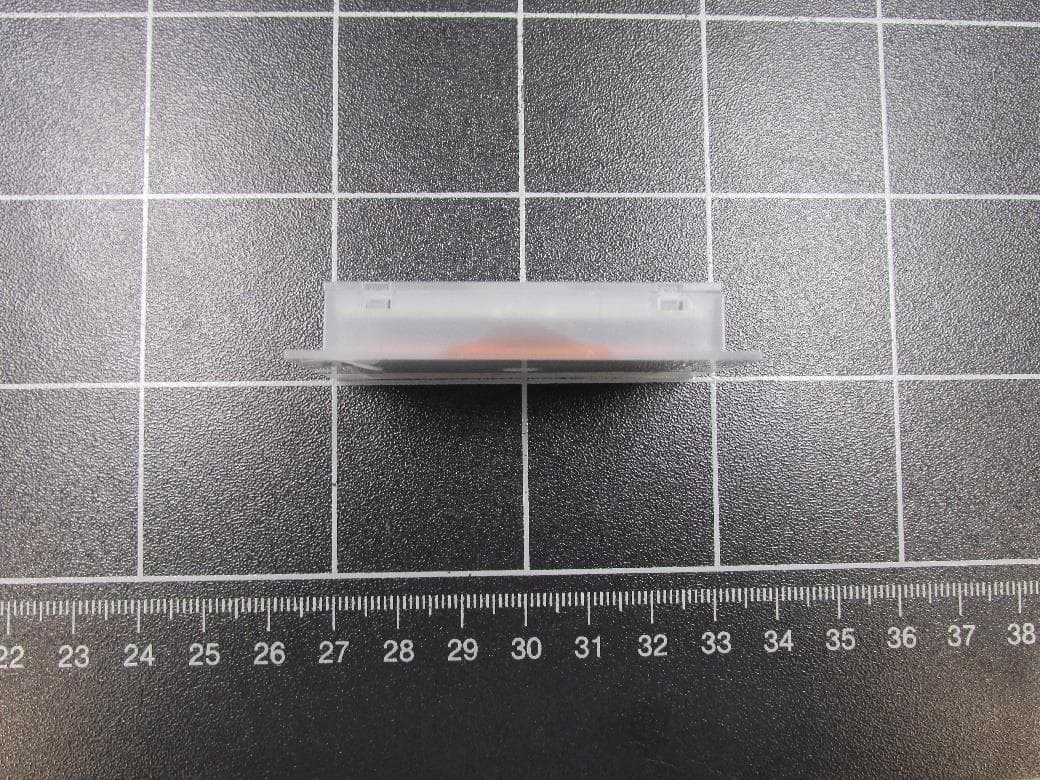
OKY10115100A06A
Jul 26, 2021RFID Card Reader
Equipment Class
DXX - Part 15 Low Power Communication Device Transmitter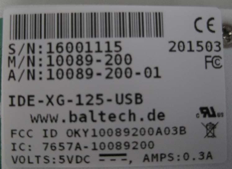
OKY10089200A03B
May 05, 2015IDE-XG-125-USB
Equipment Class
DXX - Part 15 Low Power Communication Device Transmitter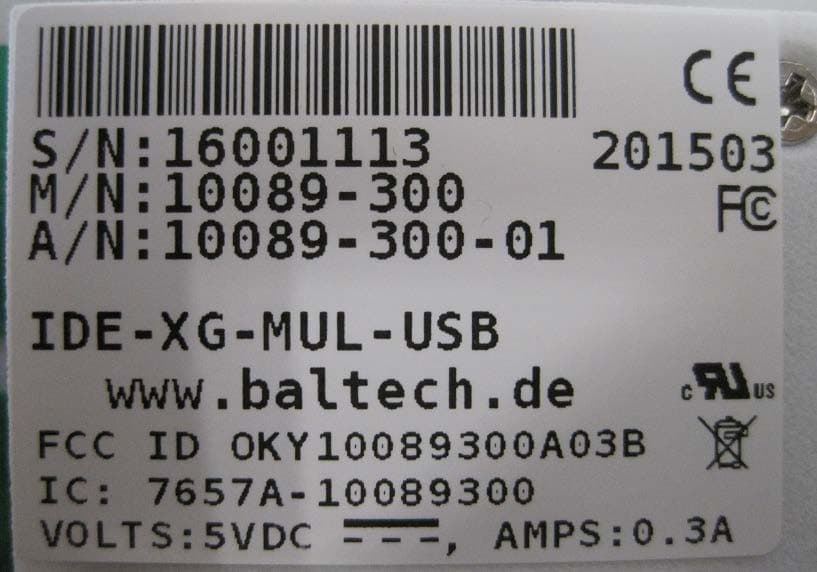
OKY10089300A03B
May 05, 2015IDE-XG-MUL-USB
Equipment Class
DXX - Part 15 Low Power Communication Device Transmitter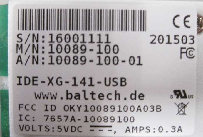
OKY10089100A03B
May 05, 2015IDE-XG-141-USB
Equipment Class
DXX - Part 15 Low Power Communication Device Transmitter