OLA-DX147FOLLOW ME
Wellmike Enterprise Co. Ltd.
Click to zoom
Application Details
- Equipment Class
- DXX - Part 15 Low Power Communication Device Transmitter
- Date of Grant
- Dec 22, 2003
- Application Purpose
- Original Equipment
- Date of Application
- Dec 22, 2003
- Equipment Note
- FOLLOW ME
- Frequency Range
- 433.42000000 - 434.42000000
- Company
- Wellmike Enterprise Co. Ltd.
- Country
- Taiwan
Documents & Files
Document Text
Text extracted from the exhibit documents filed with the FCC. Open a document above to read the original.
Users Manual
Never lose track of your portable valuables! Great for traveling! Attach the signal transmitter to your briefcase, notebook computer, or any other valuable items. Carry the receiver with you on your key chain. FEATURES: A precise, mini electronic guarding system. Perfect for safeguarding your valuable items, including Cellular Phones, Notebooks, briefcases, hand bags....etc. Rechargeable function eliminates replacement headaches and saves money. PRODUCT INCLUDES: 1pc Transmitter (TX) (Attached to your valuable) 1pc Receiver (RX) (Attached to your person) 1pc Rechargeable Base 1pc AC Adaptor OPERATING INSTRUCTIONS: 1. Turn on the Receiver (RX) unit. The red LED light will illuminate and you will hear a long beep followed by continuous short beeps. Now, the RX is ready to cooperate with Transmitter (TX) unit by learning its code. 2. Turn on the TX unit. You will hear a fast beep signal consisting of one long and one short beep. After this, the beeping sounds will stop. This indicates that the TX has successfully connected with the RX. Both red LED lights will blink simultaneously. On the other hand, if you still hear continuous beeps, you should turn both the TX & the RX off and on again to link their codes together. 3. Once the connection between the two units has been activated, you should attach the RX to your person (ie: on you key chain in your pocket) and the TX to your valuable possession (Cell phone, Notebook computer, wallet, etc.). Separating the two units by more than 6-15 feet (about 2-5 meters) will trigger 3 short beeps to sound continuously in order to remind you that you are away from your valuable. Range may vary from place to place. 4. Recharge both the RX & the TX if RX beep sounds become weak, or if their responding distance becomes shorter. 5. Always turn both units off when recharging their batteries. 6. The Rechargeable Base red LED light will illuminate during the recharging process. When the red LED light turns to green, this indicates that the RX or the TX is fully charged. Note: To follow its IC process, always turn on the RX first and the TX second. When you accidentally turn off either the RX or the TX during operation, you must turn off both units and start from the first steps of the operation as instructed above. Please keep the RX & the TX separated by at least 2/3 feet (20cm) during learning code status. This is the minimum distance required. The batteries' duration after each recharge will be around two weeks depending upon usage. Always turn both the TX & the RX to the off position when not in use. Always disconnect the AC adapter after recharging. Do not use this device when on board an airplane. Do not use this device in the rain. WARNING: Do not use any other AC Adapter with this FOLLOW ME. Furthermore do not use this Ac Adapter with any other products. FCC ID : OLA - DX-147 This device complies with Part 15 of the FCC Rules.Operation is subject to the following two conditions : (1) this device may not cause harmful interference,and (2) this device must accept any interference received, including interference that may cause undesired operation. NOTE This equipment has been tested and found to comply with the limits for a Class B digital device, pursuant to Part 15 of the FCC Rules. These limits are designed to provide reasonable protection. This equipment generates, uses and can radiated radio frequency energy and, if not installed and used in accordance with the instructions, may cause harmful interference to radio communications. However, there is no guarantee that interference will not occur in a particular installation If this equipment does cause harmful interference to radio or television reception, which can be determined by turning the equipment off and on, the user is encouraged to try to correct the interference by one or more of the following measures: Reorient or relocate the receiving antenna. Increase the separation between the equipment and receiver. Connect the equipment into an outlet on a circuit different from that to which the receiver is connected. Consult the dealer or an experienced radio/TV technician for help. The antenna(s) used for this transmitter must not be co-located or operating in conjunction with any other antenna or transmitter. Changes or modifications not expressly approved by the party responsible for compliance could void the user's authority to operate the equipment. Follow Me
Block Diagram
DX-147 TRANSMISSION BLOCK CHARGEABLE BATTERY(+3.6V) MICRO CONTROLLER DIGITAL ENCODER SAW RESONATOR 433.92 MHZ RF TRANSMISSION AMPLITUDE MODULATION
External Photos
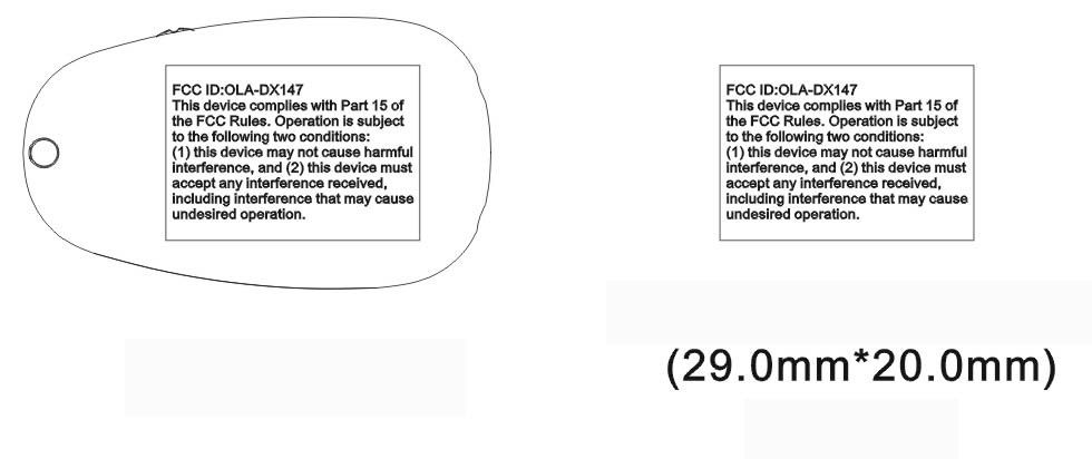
FCC ID: OLA-DX147 Number 1 FRONT SIDE OF EUT FCC ID: OLA-DX147 Number 2 REAR SIDE OF EUT FCC ID: OLA-DX147 Number 3 FRONT SIDE OF BASE FCC ID: OLA-DX147 Number 4 REAR SIDE OF BASE FCC ID: OLA-DX147 Number 5 FRONT SIDE OF ADAPTER FCC ID: OLA-DX147 Number 6 REAR SIDE OF ADAPTER FCC ID: OLA-DX147 Number 7 LABEL OF ADAPTER
Internal Photos
FCC ID: OLA-DX147 Number 1 MECHANICAL CONSTRUCTION OF EUT FCC ID: OLA-DX147 Number 2 FRONT SIDE OF MAIN BOARD OF EUT FCC ID: OLA-DX147 Number 3 REAR SIDE OF MAIN BOARD OF EUT FCC ID: OLA-DX147 Number 4 MECHANICAL CONSTRUCTION OF BASE FCC ID: OLA-DX147 Number 5 MECHANICAL CONSTRUCTION OF BASE FCC ID: OLA-DX147 Number 6 FRONT SIDE OF MAIN BOARD OF BASE FCC ID: OLA-DX147 Number 7 REAR SIDE OF MAIN BOARD OF BASE
Operational Description
Operational Description 1. The circuit function and device operates 1.1 The transmission unit being made up of 4 sections: the charge able battery +3.6v, the micro co ntroller digita l encoder, 433. 92 MHz SAW resonator and RF transmission ci rcuit (Refer to attached tr ansmission block drawing) . The code being modulated to 433.92 MHz freque ncy point, using ASK modulation type (detai ls please refer to the code description ), the frequency band width is 1 MHz. The Duty cycl e of code is 1:3. The bit rate is 1100bps. 1.2 The receiver unit being made up of 5 sections: the chargeable battery +3.6v, +3v power regula tor, RF receiver demodulation, micro controller digital decode r and alarm circuit (Refer to at tached receiver block drawing). The 433.92 MHz high frequency signal being mixed with the LOF, and output 1.8 MHz IF signal, then input to micro controller to decode, and drive the speaker by output. 1.3 When Using, power on the receiver unit at first, the LED of receive r unit will glow long time, a nd the receiver unit will s end out long sound “BE” at first, then short sound “BE”(i nterval time is 1.6s or so), then power on the transmission unit, the receiver unit will send out long sound “ BE”, which means that the study code of receiver and transmission unit is successful, at the same time the LED of receiver and transmission unit will twinkle. The r eceiver unit will not send out sound until the distance between the receiver and trans mission unit is out of the specification. When the streng th of alarm sound is too small or the rece ive distance is too short, which means to the transmission and receiver units need to charge. Put them to the charger, LED sends out red light, afte r about 2.5 hours, LED se nds out yellow light, which means to the charge is full enough.(Still have small current to go on charging, but which will not damage t he chargeable battery and charger.) 2. Attached statement 2.1 The transmission unit being put to the travel bag or box, receiver unit being ke pt with you, put it to your pocket or hang up at your waist. 2.2 The same frequency band and metal object will make the receiver distance shorten. 2.3 When charging, power off the r eceiver and transmission units. 2.4 To make the transmission and receiv er unit operate normally, pl ease keep the distance of them farer than 20cm. 3. The code description 3.1 Define: a. The start code: Occupy 1 bit code widt h. Being made up of the high level(0.56ms) and the low level(2ms). The wave type as be low: b. The data code: Occupy 16 bits code widt h. “1” means that high level is 0.56ms and low level is 0.28ms. “0” means that high l evel is 0.28ms and low level is 0.56ms. The wave type as below: c. The frame: Occupy 17 bits, being made up of 1 bit start code and 16 bits data code. 3.2 Code transmit: The TX unit transmits 3 frames every time, and the interval time of transmission betw een the first time and the next time is 80 0ms. 0.56 2.0 “1” “0” 0.56 0.28 0.28 0.56 The start code (1 bit) The data code (16 bits) CHARGEABLE BATTERY(+3.6V) MICRO CONTROLLER DIGITAL ENCODER SAW RESONATOR 433.92 MHZ RF TRANSMISSION AMPLITUDE MODULATION DX-147 TRANSMISSION BLOCK POWER REGULATOR +3V CHARGEABLE BATTERY(+3.6V) RF RECEIVER AMPLITUDE DEMODULATOR MICRO CONTROLLER DIGITAL DECODER ALARM DRIVE DX-147 RECEIVER BLOCK ENABL
Schematics
1234 A B C D 4 321 D C B A Title NumberRevisionSize A4 Date:17-Sep-2003Sheet of File:E:\TS\ts1\ts\dx147\sch1\DX-147CH .DDBDrawn By: Follow me 11 LYX BAT1 3.6V 3 2 1 8 4 U1A LM358 5 6 7 U1B LM358 Q1 2SA1162 R6 510 OHM Q3 2SC2712 LED1 LED-PIN3A R8 75 OHM R5 1K R4 100K R7 15K BAT2 3.6V Q2 2SA1162 R14 510 OHM Q4 2SC2712 LED2 LED-PIN3A R17 75 OHM R13 1K R12 100K R15 15K R1 10K1% J1 J2 C1 100uF/16V R10 200K R2 200K R18 1K R16 1K Vin 1 GND 2 +5V 3 U3 78L08 R9 18K1% R21 510 OHM R22 510 OHM R20 100K R19 100K D2 0 OHM D3 0 OHM OLD R8=47 OHM,NEW R8=75 OHM OLD R17=47 OHM,NEW R17=75 OHM 1234 A B C D 4 321 D C B A Title NumberRevisionSize A4 Date:17-Sep-2003Sheet of File:E:\TS\ts1\ts\dx147\sch1\DX-147TX .DDBDrawn By: P50 1 P67 2 P66 3 VDD 4 P65/OSC1 5 P63/RST 7 P64/OSC2 6 P62/TCC 8 P61 9 P60/INT 10 GND 11 P53 12 P52 13 P51 14 U1 EM78P153EN R1 100K R2 4.7K R3 68K R4 1K C2 102 C5 8P C3 2P D1 LED C1 104 J1 J J2 J D2 1N4148 COMMON 2 NO 1 NO 3S1 GND G 12 SAW1 HDR433M B E C Q1 MPSH10A C4 104 J3 BT+ J4 BT-
Test Report
FCC TEST REPORT Report No. : F361107 SPORTON International Inc. TEL : 886-2-2696-2468 FAX : 886-2-2696-2255 FCC TEST REPORT for 47 CFR, Part 15, Subpart C Equipment : FOLLOW ME Model No. : DX147 FCC ID : OLA-DX147 Filing Type : Certification Applicant : WELLMIKE ENTERPRISE CO., LTD. 3FL., NO. 2, LANE 497, CHUNG CHENG ROAD, HSIN TIEN, TAIPEI HSIEN, TAIWAN, R.O.C. The test result refers exclusively to the test presented test model / sample. Without written approval of SPORTON International Inc., the test report shall not be reproduced except in full. Certificate or Test Report must not be used by the applicant to claim the product in this test report endorsement by NVLAP or any agency of U.S. government. SPORTON International Inc. 6F, No.106, Sec. 1, Hsin Tai Wu Rd., Hsi Chih, Taipei Hsien, Taiwan, R.O.C. FCC TEST REPORT Report No. : F361107 SPORTON International Inc. FCC ID : OLA-DX147 TEL : 886-2-2696-2468 Page No. : i FAX : 886-2-2696-2255 Issued Date : Dec. 20, 2003 Table of Contents History of this test report....................................................................................................................................ii CERTIFICATE OF COMPLIANCE........................................................................................................................1 1. General Description of Equipment under Test.............................................................................................2 1.1. Applicant..........................................................................................................................................................................................2 1.2. Manufacturer ...................................................................................................................................................................................2 1.3. Basic Description of Equipment under Test ....................................................................................................................................2 1.4. Feature of Equipment under Test ...................................................................................................................................................3 2. Test Configuration of Equipment under Test ...............................................................................................4 2.1. Test Manner ....................................................................................................................................................................................4 2.2. Description of Test System .............................................................................................................................................................4 2.3. Connection Diagram of Test System ..............................................................................................................................................5 3. Test Software ...................................................................................................................................................6 4. General Information of Test............................................................................................................................7 4.1. Test Facility .....................................................................................................................................................................................7 4.2. Test Voltage ....................................................................................................................................................................................7 4.3. Standard for Methods of Measurement...........................................................................................................................................7 4.4. Test in Compliance with ..................................................................................................................................................................7 4.5. Frequency Range Investigated .......................................................................................................................................................7 4.6. Test Distance ..................................................................................................................................................................................7 5. Test of Conducted Powerline .........................................................................................................................8 5.1. Major Measuring Instruments..........................................................................................................................................................8 5.2. Test Procedures ..............................................................................................................................................................................9 5.3. Typical Test Setup Layout of Conducted Powerline .....................................................................................................................10 5.4. Test Result of AC Powerline Conducted Emission .......................................................................................................................11 6. Test of Radiated Emission............................................................................................................................13 6.1. Major Measuring Instruments........................................................................................................................................................13 6.2. Test Procedures ............................................................................................................................................................................14 6.3. Typical Test Setup Layout of Radiated Emission...................................................................................................…
Text truncated - open the document above for the full version.
Test Setup Photos
FCC TEST REPORT Report No. : F361107 SPORTON International Inc. FCC ID : OLA-DX147 TEL : 886-2-2696-2468 Page No. : 1 of 4 FAX : 886-2-2696-2255 Issued : Dec. 20, 2003 1.1. Photographs of Conducted Powerline Test Configuration z The photographs show the configuration that generates the maximum emission. FRONT VIEW REAR VIEW FCC TEST REPORT Report No. : F361107 SPORTON International Inc. FCC ID : OLA-DX147 TEL : 886-2-2696-2468 Page No. : 2 of 4 FAX : 886-2-2696-2255 Issued : Dec. 20, 2003 SIDE VIEW FCC TEST REPORT Report No. : F361107 SPORTON International Inc. FCC ID : OLA-DX147 TEL : 886-2-2696-2468 Page No. : 3 of 4 FAX : 886-2-2696-2255 Issued : Dec. 20, 2003 1.2. Photographs of Radiated Emission Test Configuration z The photographs show the configuration that generates the maximum emission. <Mode 1~3> FRONT VIEW REAR VIEW FCC TEST REPORT Report No. : F361107 SPORTON International Inc. FCC ID : OLA-DX147 TEL : 886-2-2696-2468 Page No. : 4 of 4 FAX : 886-2-2696-2255 Issued : Dec. 20, 2003 <Mode 4> FRONT VIEW REAR VIEW
Contact Information
Applicant
SUE LIU(SALES MANAGER)
Test Firm
SPORTON International IncKathy Lin
Technical Specifications
| # | Rule Parts | Frequency Range | Power Output |
|---|---|---|---|
| 1 | 15C | 433.42 MHz - 434.42 MHz | - |
Other Applications from Wellmike Enterprise Co. Ltd.
OLADXP122
Feb 01, 2007PC Lock
Equipment Class
DSC - Part 15 Security/Remote Control Transmitter
OLA-DX149
Mar 01, 2004SECURITY PROXIMETER
Equipment Class
DXX - Part 15 Low Power Communication Device Transmitter
OLA-DX148
Sep 22, 2003SECURITY PROXIMETER ALARM
Equipment Class
DXX - Part 15 Low Power Communication Device Transmitter
OLA-DX143T
Apr 03, 2000Briefcase Alert
Equipment Class
DSC - Part 15 Security/Remote Control Transmitter
OLA-DX4310T
Sep 29, 1999DSC - Part 15 Security/Remote Control Transmitter
Equipment Class
DSC - Part 15 Security/Remote Control Transmitter