OLADXP122PC Lock
Wellmike Enterprise Co. Ltd.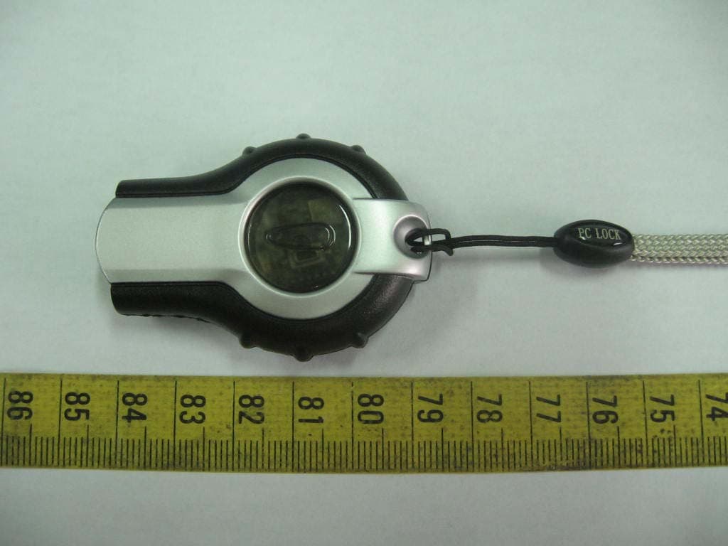
Click to zoom
Application Details
- Equipment Class
- DSC - Part 15 Security/Remote Control Transmitter
- Date of Grant
- Feb 01, 2007
- Application Purpose
- Original Equipment
- Date of Application
- Feb 01, 2007
- Equipment Note
- PC Lock
- Frequency Range
- 315.00000000 - 315.00000000
- Company
- Wellmike Enterprise Co. Ltd.
- Country
- Taiwan
Documents & Files
Document Text
Text extracted from the exhibit documents filed with the FCC. Open a document above to read the original.
Users Manual
II. Hardware Hardware Installation ............................... 2 Hardware Removal .................................. 3 III. Software Software Installation ................................. 3 Automatic Installation ................................ 3 Password Setting ..................................... 4 Product ID Recognition .............................. 5 Software Removal ..................................... 6 IV. User Guide ............................................... 7 V. Frequently Asked Questions ....................... 10 VI. Technical Support and Service ..................... Model : Wireless PC Lock Accessories : 1. Transmitter unit × 1 / Receiver unit × 1 2. 3V (CR2032) Battery × 1 3. Driver CD × 1 Function : 1. The computer automatically enters “ Lock Mode ” when the user is away from computer by more than 2 meters 2. The computer automatically resumes normal operation when the user is back to within 2 meters range 3. Once the computer enters the “ Lock Mode ” a password is required to use the computer if the transmitter/receiver pair is not available to unlock the computer 4. One transmitter can be shared with several computers 5. The computer will signal “ Warning ” when battery voltage of the transmitter is too low Specifications : 1. One unique “ Security Code ” in the Transmitter Computer automatically recognizes the code itself 2. A maximum of 5 sets of “ Password ” and each set allows maximum of 125 numbers/characters (case insensitive) 3. Operation frequencies: □ FCC/315MHz;□ CE/434MHz 4. Transmitter Power Supply: DC 3V 5. Battery Usage: approximately 2000 hours 6. Receiver Power Supply: DC 5V, provided by the computer through USB port 7. Software Driver: support Windows 98 SE / ME / 2000 / XP Hardware Installation A. Insert the Wireless PC Lock receiver into the USB port and the computer will automatically detect and determine if the hardware is properly installed. B. If computer fails to detect the receiver device after the hardware installation, the following window will display on the screen. Click the “ Exit “ button and repeat the above step again. 第 2 頁,共 10 頁Table of Contents 2003/10/30file://C:\tmp\安規\SEND\FOR%20FCC\Eng\ENG.htm C. If the following window is displayed on the screen, click the “ OK “ button to cancel the installation. ** Please double check to see if (a) the USB port is fully functional, and (b) the Wireless PC Lock receiver is properly inserted into the USB port. Software Installation Automatic Installation Place the driver software CD which comes with the Wireless PC Lock in the CD-ROM driver and the computer will automatically read and execute the installation program. The computer screen will look similar to the one below. To install the software, simply follow the on-screen instructions. Click the “ OK “ button to start the installation. 第 3 頁,共 10 頁Table of Contents 2003/10/30file://C:\tmp\安規\SEND\FOR%20FCC\Eng\ENG.htm When the software is installing, the computer screen will look similar to the one below. Once the software installation is completed, click the “ OK “ button. 第 4 頁,共 10 頁Table of Contents 2003/10/30file://C:\tmp\安規\SEND\FOR%20FCC\Eng\ENG.htm Password Setting After the software driver installation is completed, the screen will look similar to the picture below. Please set at least one valid password. The Wireless PC Lock software accommodates a maximum of five (5) sets of passwords with up to 125 alpha-numeric characters in each password. Please note that the alpha-numeric characters in each password are case insensitive. In the pull-down menu of the password setting screen, you may choose a Password Reminder or leave it blank. If a color key is chosen as the Password Reminder , please note that only White, Cyan, Red, Magenta, Yellow, Black, Green, and Blue colors are available. Product ID Recognition An ID recognize procedure must be completed prior to using the product. Recognize Procedure: (a) Please make sure the transmitter is turned off. (b). After the password is successfully set, the following window will display on the screen indicating that the recognition is in progress. The transmitter may now be turned on. (c) The following pop-window indicates that the ID recognize process is complete. If the time limit is exceeded during the recognition process, a warning window will pop-up as shown in the following illustration. To proceed, click the “ Rerecognize “ button to retry the recognition right away or the “ Cancel “ button to try again later. 第 5 頁,共 10 頁Table of Contents 2003/10/30file://C:\tmp\安規\SEND\FOR%20FCC\Eng\ENG.htm
Users Manual
** Causes for exceeding time limit: ** Actions: 1. Transmitter is off Turn on transmitter and make sure its LED blinks 2. More than two transmitters nearby Follow recognize procedure to re-recognize 3. Off air RF interference Move transmitter closer to receiver until receiver’s LED blinks Software Removal There are two ways to uninstall the Wireless PC Lock software: 1. Click the Start button, select the All Programs menu button, and then select the Uninstall option in the Wireless PC Lock menu. 2. Click the Start button, select the Control Panel menu button, click the Add or Remove Programs icon, and then select the Window PC Lock program in the Add/Remove menu. l 第 6 頁,共 10 頁Table of Contents 2003/10/30file://C:\tmp\安規\SEND\FOR%20FCC\Eng\ENG.htm User’s Guide 1. The following taskbar icon indicates normal operation mode. 2. The following taskbar icon indicates computer lock-down mode. ** Lock -down mode : a. When the user walks away from the computer beyond the effective distance threshold, The receiver loses the transmitter signal and thus the computer enters lock-down mode. b. The transmitter under turn – off status. 3. Use the right button of mouse to open the context sensitive menu to select the ID Recognize, Emergency Rescue, Manual Lock, Force Lock, Help and About functions. a. ID Recognize : ID Recognize is required every time a new transmitter is used. 第 7 頁,共 10 頁Table of Contents 2003/10/30file://C:\tmp\安規\SEND\FOR%20FCC\Eng\ENG.htm b. Changing Password : c. Manual Lock : In any situation, click this button to force the computer to switch to Lock-down Mode by a valid password. d. Force Lock (1). This function forces the computer to enter the Lock-down Mode within 10 seconds, ignoring any signal from the transmitter during that period of time. (2). A short-cut is shown in the following illustration. By moving the mouse to the Wireless PC Lock taskbar icon and double-clicking the left mouse button, the Force Lock function is activated. e. Some typical screen displays: (a) Normal Mode: 第 8 頁,共 10 頁Table of Contents 2003/10/30file://C:\tmp\安規\SEND\FOR%20FCC\Eng\ENG.htm (b) Warning of Incorrect Password: (c) Warning of Missing Hardware: Frequently Asked Questions Q1 : Why can the computer not be locked? A1 : The locking range may be enhanced by electro-magnetic interference in the surrounding area. Use the “ Manual Lock” / “ Force Lock” / “ special function key ” to enter Lock-down Mode by a valid password. Q2 : Does the Wireless PC Lock support any computer operation systems ? A2 : No. The computer operation system must offer USB port support, and this driver support for operation system in Windows 98SE / ME / 2000 / XP. If the computer does not have a USB port, please purchase a USB interface card and Install the card in computer. Q3 : Can Wireless PC Lock affect or terminate other running software programs? A3 : No. Although the screen is locked, the other running programs remain unaffected. Q4 : Can the locking function be activated simply with the installation of the software driver? A4 : Yes. However, the hardware must first be successfully installed. Q5 : How many alpha-numeric characters are accepted in the password setting screen? 第 9 頁,共 10 頁Table of Contents 2003/10/30file://C:\tmp\安規\SEND\FOR%20FCC\Eng\ENG.htm A5 : 125 characters maximum per password. Q6 : Why does the battery die so quickly? A6 : One CR2032 (3V) battery should be able to support 2000 hours of continuous usage. Due to the self leakage of the battery itself, please pay special attention to the expiration date of the battery itself. Q7 : Can multiple computers be controlled by a single transmitter? A7 : Yes, as long as both the receiver hardware and software driver were installed in every computer and the transmitter ID was ratified on each computer. Q8 : Why does the transmitter unable to control the computer even after the ID recognition has been completed ? A9 : There may have been more than one ID recognition process on-going during the same time. Follow the ID Recognize procedure and click the “ Rerecognize “ button again. Notes (1) During normal operation, the minimum locking range threshold may be affected by many factors such as nearby metallic material, RF interference, etc.. (2) Avoid exposing the product to excessive moisture or vibration. 第 10 頁,共 10 頁Table of Contents 2003/10/30file://C:\tmp\安規\SEND\FOR%20FCC\Eng\ENG.htm
Cover Letter(s)
910805 2 WELLMIKE ENTERPRISE CO., LTD. 3 FL. No.2, Lane 497, Chung Cheng Road, Hsin Tien, Taipei Hsien, Taiwan Tel : (02) 2218-3822 (REP.) 2218-6800 Fax : (02) 2218-1804 E-Mail Address : [email protected] To whom it may concern: We, the undersigned, hereby authorize ELECTRONICS TESTING CENTER, TAIWAN, to act on our behalf in all manners relating to application for equipment authorization, including signing of all documents relating to these matters. Any and all acts carried out by ELECTRONICS TESTING CENTER, TAIWAN on our behalf shall have the same effect as acts of our own. We, the undersigned, hereby certify that we are not subject to a denial of federal benefits, that includes FCC benefits, pursuant to Section 5301 of the Anti-Drug Abuse Act of 1988, 21 U.S.C. 853(a). In authorizing ELECTRONICS TESTING CENTER, TAIWAN as our agent, we still recognize that we are responsible to: a) comply with the relevant provisions of the certification program; b) make all necessary arrangements for the conduct of the evaluation, including provision for examining documentation and access to all areas, records (including internal audit reports) and personnel for the purposes of evaluation (e.g. testing, inspection, assessment, surveillance, reassessment) and resolution of complaints; c) make claims regarding certification only in respect of the scope for which certification has been granted; d) do not use our product certification in such a manner as to bring the Certification Division into disrepute and not make any statement regarding our product certification which the Certification Division may consider misleading or unauthorized; e) upon suspension or cancellation of certification, discontinue use of all advertising matter that contains any reference thereto and return any certification documents as required by the Certification Division; f) use certification only to indicate the products are certified as being in conformity with specified standards; g) endeavor to ensure that no certificate or report nor any part thereof is used in a misleading manner; 910805 3 h) ensure that any reference to our product certification in communication media such as documents, brochures or advertising, complies with the requirements of the Certification Division; i) keep a record of all complaints made known to the us relating to the product’s compliance with requirements of the relevant standard and to make these records available to the Certification Division when requested; j) take appropriate action with respect to such complaints and any deficiencies found in products or services that affect compliance with the requirements for certification; k) document the actions taken. This authorization is valid until further written notice from the applicant. Sincerely Yours, SUE LIU / SALES MANAGER WELLMIKE ENTERPRISE CO., LTD. 3FL, NO. 2, L 497, CHUNG CHENG RD., HSIN TIEN, TAIPEI HSIEN, TAIWAN, R.O.C.
Cover Letter(s)
910805 4 WELLMIKE ENTERPRISE CO., LTD. 3 FL. No.2, Lane 497, Chung Cheng Road, Hsin Tien, Taipei Hsien, Taiwan Tel : (02) 2218-3822 (REP.) 2218-6800 Fax : (02) 2218-1804 E-Mail Address : [email protected] Federal Communications Commission FCC ID: OLADXP122 Product Name: PC LOCK Model Name: DX-P122 Trade Name: WELLMIKE Dear Sir: In accordance with 47 C.F.R. Section 0.459, we would like to request confidentiality on some exhibits we submitted for above application for the reason of trade secret. If those exhibits are available for public inspection, any person who once gets the information contained in those exhibits will be able to design and to make the same products very easily. This is a very serious problem and huge loss for us, because we did invest so much on it. Please be not made the Exhibit Types listed below routinely available for public inspection: Block Diagram and Schematics. By: By: SUE LIU Title : SALES MANAGER Applicant : WELLMIKE ENTERPRISE CO., LTD. Address : 3FL, NO. 2, LANE 497, CHUNG CHENG RD, HSIN TIEN, TAIPEI HSIEN, TAIWAN, R.O.C. Tel : 886-2-2218-3822 Fax: 886-2-2218-1804 Date : 2006-11-01
External Photos
ETC Report No.:06-10-RBF-097-01 FCC ID.: OLADXP122 Rev. No 1.0 CONSTRUCTED PHOTOS of EUT Top View of EUT Rear View of EUT ETC Report No.:06-10-RBF-097-01 FCC ID.: OLADXP122 Rev. No 1.0 CONSTRUCTED PHOTOS of EUT Side View of EUT Front View of EUT ETC Report No.:06-10-RBF-097-01 FCC ID.: OLADXP122 Rev. No 1.0 CONSTRUCTED PHOTOS of EUT Side View of EUT Bottom View of EUT
Internal Photos
ETC Report No.:06-10-RBF-097-01 FCC ID.: OLADXP122 Rev. No 1.0 CONSTRUCTED PHOTOS of EUT Internal View of EUT ETC Report No.:06-10-RBF-097-01 FCC ID.: OLADXP122 Rev. No 1.0 CONSTRUCTED PHOTOS of EUT Component View of Main PCB Solder View of Main PCB
Test Report
Rev. No 1.0 FCC Part 15 EMI TEST REPORT of E.U.T. : PC LOCK FCC ID. : OLADXP122 MODEL : DX-P122 Working Frequency : 315 MHz for APPLICANT : WELLMIKE ENTERPRISE CO., LTD. ADDRESS : 3FL, NO. 2, LANE 497, CHUNG CHENG RD, HSIN TIEN, TAIPEI HSIEN, TAIWAN, R.O.C. Test Performed by ELECTRONICS TESTING CENTER, TAIWAN NO.34, LIN 5, DINGFU TSUEN, LINKOU SHIANG TAIPEI COUNTY, TAIWAN, 24442, R.O.C. Tel : (02)26023052 Fax : (02)26010910 http://www.etc.org.tw ; e-mail: [email protected] Report Number : 06-10-RBF-097-01 ETC Report No.:06-10-RBF-097-01 FCC ID.: OLADXP122 Rev. No 1.0 TEST REPORT CERTIFICATION Applicant : WELLMIKE ENTERPRISE CO., LTD. 3FL, NO. 2, LANE 497, CHUNG CHENG RD, HSIN TIEN, TAIPEI HSIEN, TAIWAN, R.O.C. Manufacturer : WELLMIKE INDUSTRIES (SHEN ZHEN) LTD. NO. 7, LANE 1, DAN FENG STREET, SILI ROAD, GUAN LAN TOWN, SHEN ZHEN CITY, GUANG DONG, CHINA Description of EUT a) Type of EUT : PC LOCK b) Trade Name : WELLMIKE c) Model No. : DX-P122 d) FCC ID : OLADXP122 e) Working Frequency : 315 MHz f) Power Supply : DC 3V Regulation Applied : FCC Rules and Regulations Part 15 Subpart C (2006) I HEREBY CERTIFY THAT; The data shown in this report were made in accordance with the procedures given in ANSI C63.4 and the energy emitted by the device was founded to be within the limits applicable. I assume full responsibility for accuracy and completeness of these data. Note : 1. The results of the testing report relate only to the items tested. 2. The testing report shall not be reproduced except in full, without the written approval of ETC. Issued Date : Jan. 12, 2007 Test Engineer : ( Vincent Chang ) Approve & Authorized Signer : Will Yauo, Manager EMC Dept. II of ELECTRONICS TESTING CENTER, TAIWAN ETC Report No.:06-10-RBF-097-01 FCC ID.: OLADXP122 Rev. No 1.0 Table of Contents Page 1. GENERAL INFORMATION ............................................................................................................................... 1 1.1 PRODUCT DESCRIPTION.......................................................................................................................................... 1 1.2 CHARACTERISTICS OF DEVICE: ...............................................................................................................................1 1.3 TEST METHODOLOGY............................................................................................................................................. 1 1.4 TEST FACILITY........................................................................................................................................................ 1 2. DEFINITION AND LIMITS ................................................................................................................................ 2 2.1 DEFINITION............................................................................................................................................................. 2 2.2 RESTRICTED BANDS OF OPERATION....................................................................................................................... 2 2.3 LIMITATION............................................................................................................................................................ 2 2.4 LABELING REQUIREMENT....................................................................................................................................... 4 2.5 USER INFORMATION............................................................................................................................................... 4 3 SYSTEM TEST CONFIGURATION ................................................................................................................... 5 3.1 JUSTIFICATION........................................................................................................................................................ 5 3.2 DEVICES FOR TESTED SYSTEM................................................................................................................................5 4. RADIATED EMISSION MEASUREMENT ...................................................................................................... 6 4.1 APPLICABLE STANDARD......................................................................................................................................... 6 4.2 MEASUREMENT PROCEDURE................................................................................................................................... 6 4.3 TEST DATA............................................................................................................................................................. 8 4.3.1 Tx Fundamental and Harmonics.................................................................................................................... 8 4.3.2 Other Emissions ............................................................................................................................................. 9 4.4 FIELD STRENGTH CALCULATION.......................................................................................................................... 10 4.5 ACTIVATE TIME.................................................................................................................................................... 10 4.6 CALCULATION OF DUTY FACTOR.......................................................................................................................... 10 4.7 RADIATED TEST EQUIPMENT................................................................................................................................11 4.8 MEASURING INSTRUMENT SETUP......................................................................................................................... 11 4.9 RADIATED MEASUREMENT PHOTOS...................................................................................................................... 12 5. BANDWIDTH OF EMISSIO…
Text truncated - open the document above for the full version.
Test Setup Photos
ETC Report No.:06-10-RBF-097-01 FCC ID.: OLADXP122 Rev. No 1.0 Radiated Measurement Photos
Contact Information
Applicant
SUE LIU(SALES MANAGER)
Test Firm
Electronics Testing Center, TaiwanWill Yauo
Technical Specifications
| # | Rule Parts | Frequency Range | Power Output |
|---|---|---|---|
| 1 | 15.231(e) | 315 MHz - 315 MHz | - |
Other Applications from Wellmike Enterprise Co. Ltd.

OLA-DX149
Mar 01, 2004SECURITY PROXIMETER
Equipment Class
DXX - Part 15 Low Power Communication Device Transmitter
OLA-DX147
Dec 22, 2003FOLLOW ME
Equipment Class
DXX - Part 15 Low Power Communication Device Transmitter
OLA-DX148
Sep 22, 2003SECURITY PROXIMETER ALARM
Equipment Class
DXX - Part 15 Low Power Communication Device Transmitter
OLA-DX143T
Apr 03, 2000Briefcase Alert
Equipment Class
DSC - Part 15 Security/Remote Control Transmitter
OLA-DX4310T
Sep 29, 1999DSC - Part 15 Security/Remote Control Transmitter
Equipment Class
DSC - Part 15 Security/Remote Control Transmitter