OM4SLV-MA-USTelevoter Master and Slave Antennas
Logos Av Com S.r.l.
Click to zoom
Application Details
- Equipment Class
- DXT - Part 15 Low Power Transceiver, Rx Verified
- Date of Grant
- Feb 29, 2004
- Application Purpose
- Original Equipment
- Date of Application
- Feb 29, 2004
- Equipment Note
- Televoter Master and Slave Antennas
- Frequency Range
- 916.50000000 - 916.50000000
- Company
- Logos Av Com S.r.l.
- Country
- Italy
Documents & Files
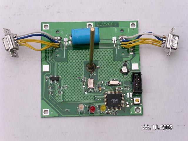
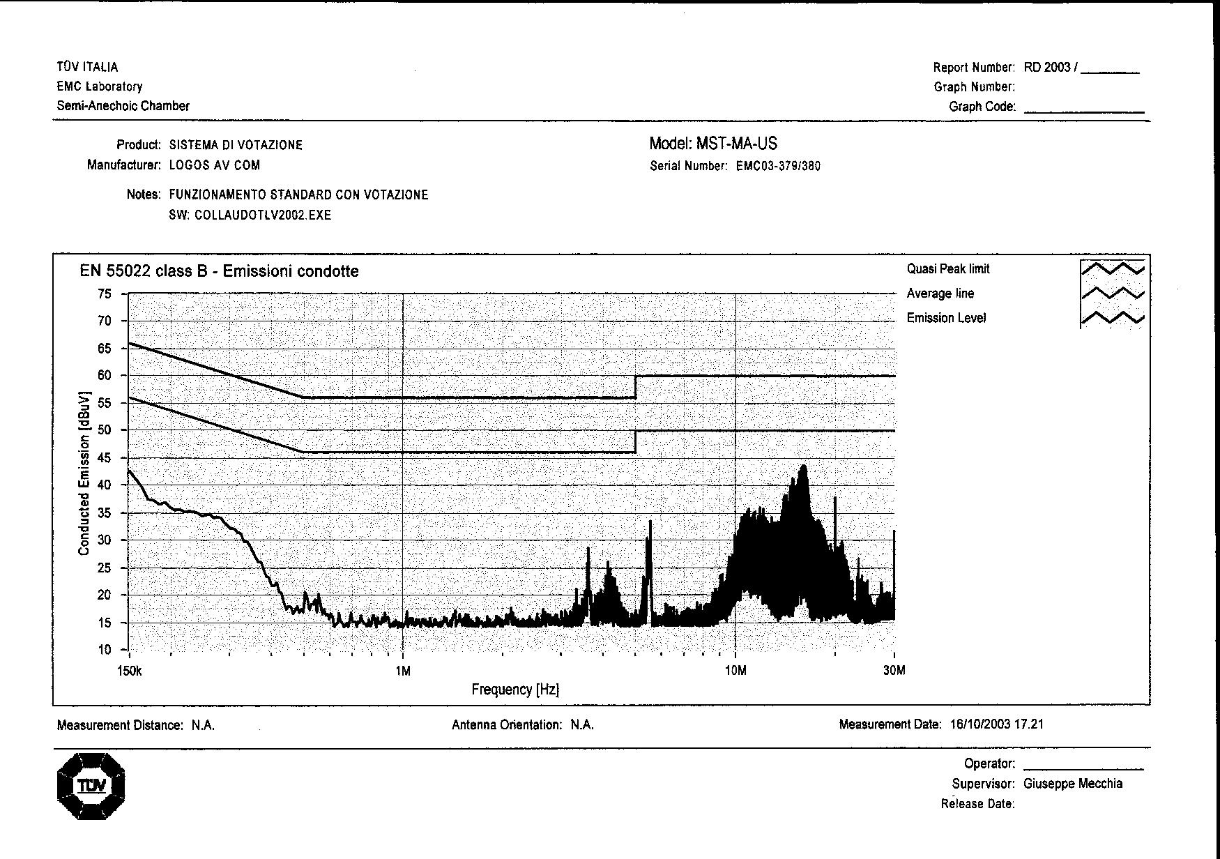
Document Text
Text extracted from the exhibit documents filed with the FCC. Open a document above to read the original.
Users Manual
Logos Av Com – Viale Risorgimento, 22 – 48018 Faenza – Italy Tel +39 0546 622 0809 – Fax +39 0546 622 090 - www.logosav.com Televoter Master (MST-MA-US) and Slave Antennas (FCC ID: OM4TLV-MA-US) USER MANUAL 1- Slave antennas set-up: Slave antennas are supplied in three parts which have to be assembled as following: - Screw down the brass antenna into the the hole, in the center of the round plate, avoiding side knoks. - Insert the alluminium pipe into the base and extend the support up to 2 mt max. - Insert the antenna box at the top of the extensible pipe. 2 - Apparate connecting: The Master Unit is designed to use a separate power supply. Each commercial DC power supply, with output 12V dc ?20%, 15 A is acceptable. The power is supplied to the master through a 2 contact circular connectors (male) fixed on the back of the Master; the relative female connector is supplied by Logos. On the rear panel of the master are four Canon 9 pole connectors: - the female one is for PC RS232 connection - the males are for connecting slave antennas by means of a RS485 line. Connect the special cable, supplied with the system, to the PC serial line, before the switching on of the PC and of the Master himself and shut the fixing screws. The connector which have to be screwed to the PC is signed with a label (the connection is mono- directional). Connect slave antennas in series by means of the 25 mt cables supplied with the system. These cable transport signals and power to slaves antennas (9 to 12 Volts). Each cable is equipped with Canon 9 pin, male and female connector, as it is each slave antenna. A maximum of 32 antennas could be connected to the Master and could be distributed on three lines or all connected on one line only. Slave antennas have an efficiency of 20 mt radius and the efficiency field must be overlapped, so that each voting pad could be received, contemporarily, by more than one antenna. At the end of each line of slave antennas must be connected a terminator, a special connector supplied with the Master Unit, the RS485 lines not used, must be terminated directly on the rear panel of the master Unit. Remember to shut the fixing screws. RS485 cables, supplied with the system can be joined to reach distances of mote than 25 mt; additional 50 mt cables are available. PC Master Rs232 Rs485 Rs485 Rs485 Possible set Up layout for 7 antennas Slave Antenna Power supply 12Vdc - 1,5 A About 20 mt distance between Slave antennas After all the connections are made, the Master Unit and the PC can be switched on. The software developers must use, exclusively, the instructions of the “Communication Protocol” distributed by Logos Av Com srl. 3 – Caution – Changes or modification not expressly approved by the manufacturer for compliance could void the user’s authority to operate the system. NOTE . This equipment has been tested and found to comply with the limits for Class B digital device, pursuant to part 15 of the FCC Rules. These limits are designed to provide reasonable protection against harmful interface in a residential installation. This equipment generates, uses and can radiate radio frequency energy and, if not installed and used in accordance with this instructions, may cause harmful interface to radio communication. However, there is no guarantee that interface will not occur in a particular installation. If this equipment does cause harmful interface to radio or television reception, which can be determined by turning this equipment off and on, the user is encouraged to try to correct the interference by one or more of the following measures: - Reorient or relocate the receiving antenna. - Increase the separation between the equipment and receiver. - Connect the equipment into an outlet on a circuit different from that to which the receiver is connected. - Consult the dealer or an experienced radio/TV technician for help.
Block Diagram
Block Diagram of the EUT (SLV-MA-US) Linear regulator 5 Mhz Quartz Microcontroller and logic Tr1000 - 916.50 Mhz RS 485 interface 3.5 Vdc Modulation & Control Bias Data Slicer Analog Digital Signal Stream TX Amplif RX Amplif Saw Filter TX data RX data Control data
ID Label/Location Info
Televoter Slave SLV–MA-US Logos Av Com – Faenza – Italy FCC ID: OM4 SLV–MA-US This device complies with part 15 of the FCC rules. Operation is subjected to the following two conditions: (1)this device may not cause harmful interference and (2) this device must accept any interference received, including interference that may cause undesired operations
Operational Description
Televoter Master and Slaves Operational Description 1.1 Product description EUT is s transceiver designed to be able to send command to one or more keypad and to receive data from them (FCC ID: OM4SLV-MA-US) whether to receive command from the Master Unit (MST-MA-US) and send data to the same. The Slave is composed of a metal box containing an electronic card with the logics, the RF transmission and reception of data (transceiver), with 1 antenna screwed into his own socket, which is welded on BCB 1.1.1 Operational description The system (Slaves and Master) recognize up to 16.383 voting keypads, divided in 32 blocks of 512 each. When requested by the operator, who control the Master Unit through the PC, a command is sent to the installed slave antennas. One or more slave antennas (FCCID: OM4SLV-MA-US) could be connected to the Master; up to 32. Then, the installed slave antennas, one after the other, send a command on air, being able to be received by all the keypad present in the area. After this command the keypad owners are allowed to enter their choice through the keyboard. Later, when closing the voting is decided, a second command is sent by the operator through the Master to the antennas, so the antennas, one by one, send on air a command, being able to be understood by the voting keypad, which pertain to the first block of voting pads present in the area. After this command the antennas switch themselves in “receiving mode” in order to receive, one after the other, the data stored into the voting pad pertaining to the first block. In this way the system can interrogate by air (TX/RX mode) the available voting keypad (FCC ID: OM4TLV-MA-US) one block at a time, being able to recognize, properly, each voting keypad pertaining the block and receives from each Voting keypad the data indicating the key/s that has/have been previously selected. This data was, previously, stored into the internal memory of the voting keypad. Immediately after being received, this data (identifying the voting keypad and the given vote) are sent to the Master Unit (MST-MA-US) through a cable connection RS 485. In the meantime the slave antennas are collecting another block of pad, until all the present block of voting keypad are collected. The Master Unit is connected to an outside PC ,through a standard serial port RS232, for the processing and displaying of the results. 1.1.2 Modulation upon the carrier - only one frequency is used: 916.50 MHz - modulation type: AFK - data rate max: 56 Kbps
Test Report
Test Report No. RD2003/208bis FCC ID: OM4SLV-MA-US Date November 24 th , 2003 TÜV ITALIA 1/19 MEASUREMENT/TECHNICAL REPORT FCC Part 15 Sections 15.207, 15.209, 15.249 Logos Av Com FCC ID: OM4SLV-MA-US November 24 th , 2003 This report concerns (check one): Original grant __X__ Class II change____ Equipment type: TELEVOTER SLAVE (ex.: computer, printer, modem, etc.) Deferred grant request per 47 CFR 0.457(d)(1)(ii)? yes _____ no __X__ If yes, defer until: ______________ date Company Name agrees to notify the Commission by ______________ date of the intended date of announcement of the product so that the grant can be issued on that date. Report prepared by: Giuseppe MECCHIA TÜV ITALIA srl Via Montalenghe 12 10010 Scarmagno ( TO ) Italy Phone : +39-0125-636911 Fax : +39-0125-636999 Test Report No. RD2003/208bis FCC ID: OM4SLV-MA-US Date November 24 th , 2003 TÜV ITALIA 2/19 Table of Contents Page 1GENERAL INFORMATION ................................................................ 3 1.1 Product Description ................................................................ 3 1.1.1 Operational description ......................................... 3 1.1.2 Modupation upon the carrier ................................. 3 1.2 Related Submittal(s)/Grant(s)................................................. 4 1.3 Tested System Details............................................................ 5 1.4 Test Methodology..................................................................... 6 1.5 Test Facility............................................................................... 6 1.6 Test Equipment List................................................................. 6 2PRODUCT LABELING........................................................................ 7 3SYSTEM TEST CONFIGURATION.................................................... 8 3.1 Justification............................................................................... 8 3.2 EUT Exercise Software........................................................... 9 3.3 Special Accessories................................................................ 9 3.4 Equipment Modifications......................................................... 9 3.5 Configuration of the Tested System....................................... 10 Figure 3.1 Configuration of the Tested System............................ 10 4BLOCK DIAGRAM(S) OF THE EUT..................................................11 4.1 Block Diagram Description......................................................11 Figure 4.1 Block Diagram of the EUT..........................................12 5CONDUCTED AND RADIATED MEASUREMENT PHOTOS.......13 6CONDUCTED EMISSION DATA.......................................................14 7RADIATED EMISSION DATA............................................................15 7.2 Field Strength Calculation.......................................................16 8PHOTOS OF TESTED EUT...............................................................17 User Manual..................................................................................................18 Test Report No. RD2003/208bis FCC ID: OM4SLV-MA-US Date November 24 th , 2003 TÜV ITALIA 3/19 1 GENERAL INFORMATION 1.1 Product description EUT is s transceiver designed to be able to send command to one or more keypad and to receive data from them (FCC ID: OM4SLV-MA-US) whether to receive command from the Master Unit (MST-MA-US) and send data to the same. The Slave is composed of a metal box containing an electronic card with the logics, the RF transmission and reception of data (transceiver), with 1 antenna screwed into his own socket, which is welded on BCB 1.1.1 Operational description The system (Slaves and Master) recognize up to 16.383 voting keypads, divided in 32 blocks of 512 each. When requested by the operator, who control the Master Unit through the PC, a command is sent to the installed slave antennas. One or more slave antennas (FCCID: OM4SLV-MA-US) could be connected to the Master; up to 32. Then, the installed slave antennas, one after the other, send a command on air, being able to be received by all the keypad present in the area. After this command the keypad owners are allowed to enter their choice through the keyboard. Later, when closing the voting is decided, a second command is sent by the operator through the Master to the antennas, so the antennas, one by one, send on air a command, being able to be understood by the voting keypad, which pertain to the first block of voting pads present in the area. After this command the antennas switch themselves in “receiving mode” in order to receive, one after the other, the data stored into the voting pad pertaining to the first block. In this way the system can interrogate by air (TX/RX mode) the available voting keypad (FCC ID: OM4TLV-MA-US) one block at a time, being able to recognize, properly, each voting keypad pertaining the block and receives from each Voting keypad the data indicating the key/s that has/have been previously selected. This data was, previously, stored into the internal memory of the voting keypad. Immediately after being received, this data (identifying the voting keypad and the given vote) are sent to the Master Unit (MST-MA-US) through a cable connection RS 485. In the meantime the slave antennas are collecting another block of pad, until all the present block of voting keypad are collected. The Master Unit is connected to an outside PC ,through a standard serial port RS232, for the processing and displaying of the results. 1.1.2 Modulation upon the carrier - only one frequency is used: 916.50 MHz - modulation type: AFK Test Report No. RD2003/208bis FCC ID: OM4SLV-MA-US Date November 24 th , 2003 TÜV ITALIA 4/19 - data rate max: 56 Kbps 1.2 Related Submittal(s)/Grant(s) FCC ID: OM4TLV-MA-US Test Report No. RD2003/208bis FCC ID: OM4SLV-MA-US Date November 24 th , 2003 TÜV ITALIA 5/19 1.3 Tested System Details The FCC IDs fo…
Text truncated - open the document above for the full version.
Test Setup Photos
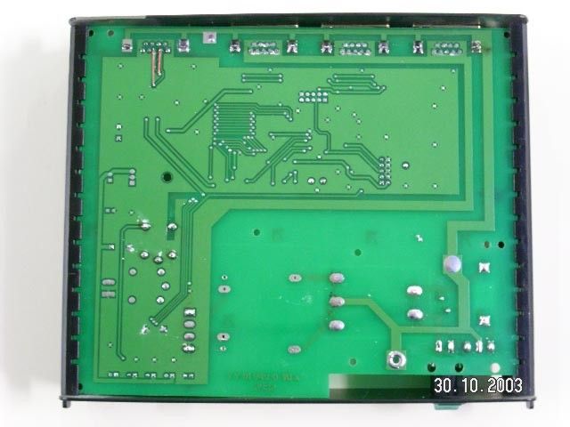
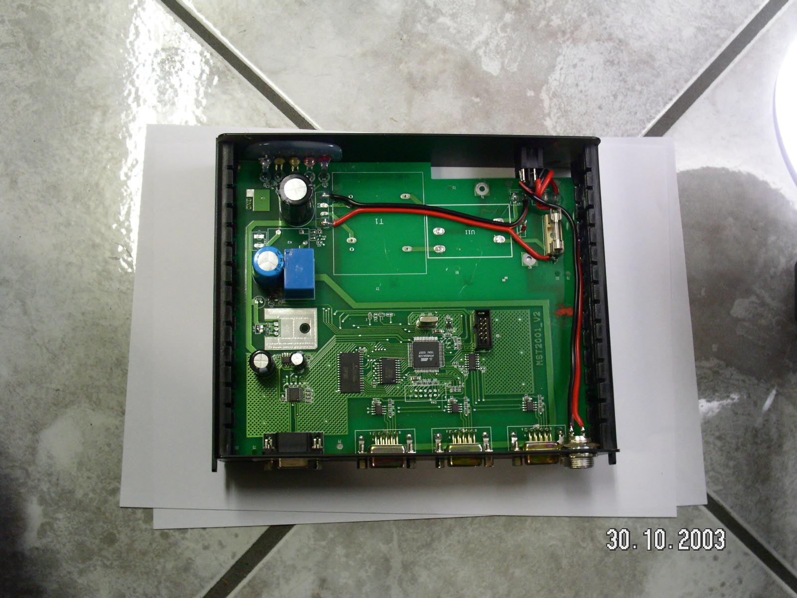
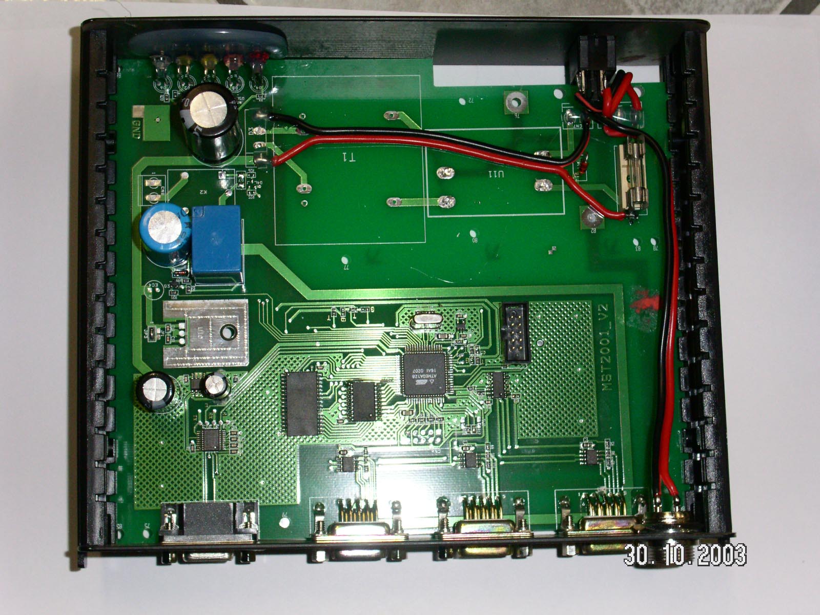
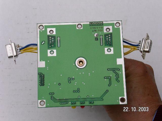
OM4SLV-MA-US - TEST SET-UP PHOTOS
Contact Information
Applicant
Sergio Sangiorgi(President)
39-0546-622-080Fax: 39-0546-622-090
Technical Contact
AmericanTCBWilliam H Graff
[email protected]703 847 4700
6731 Whittier Ave · Mclean, Virginia · United States
Test Firm
TUV ItaliaGiuseppe Mecchia
Technical Specifications
| # | Rule Parts | Frequency Range | Power Output |
|---|---|---|---|
| 1 | 15C | 916.5 MHz - 916.5 MHz | - |
Other Applications from Logos Av Com S.r.l.

OM4TLV-MA-US
Feb 29, 2004Televoter Voting Keypad
Equipment Class
DXX - Part 15 Low Power Communication Device Transmitter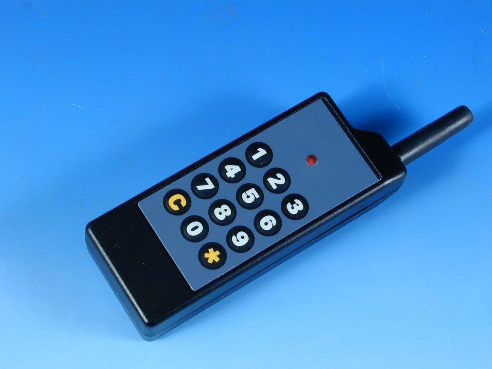
OM4TLVKPD4K
Feb 24, 2000Keypad for Televoter Wireless Audience
Equipment Class
DXX - Part 15 Low Power Communication Device Transmitter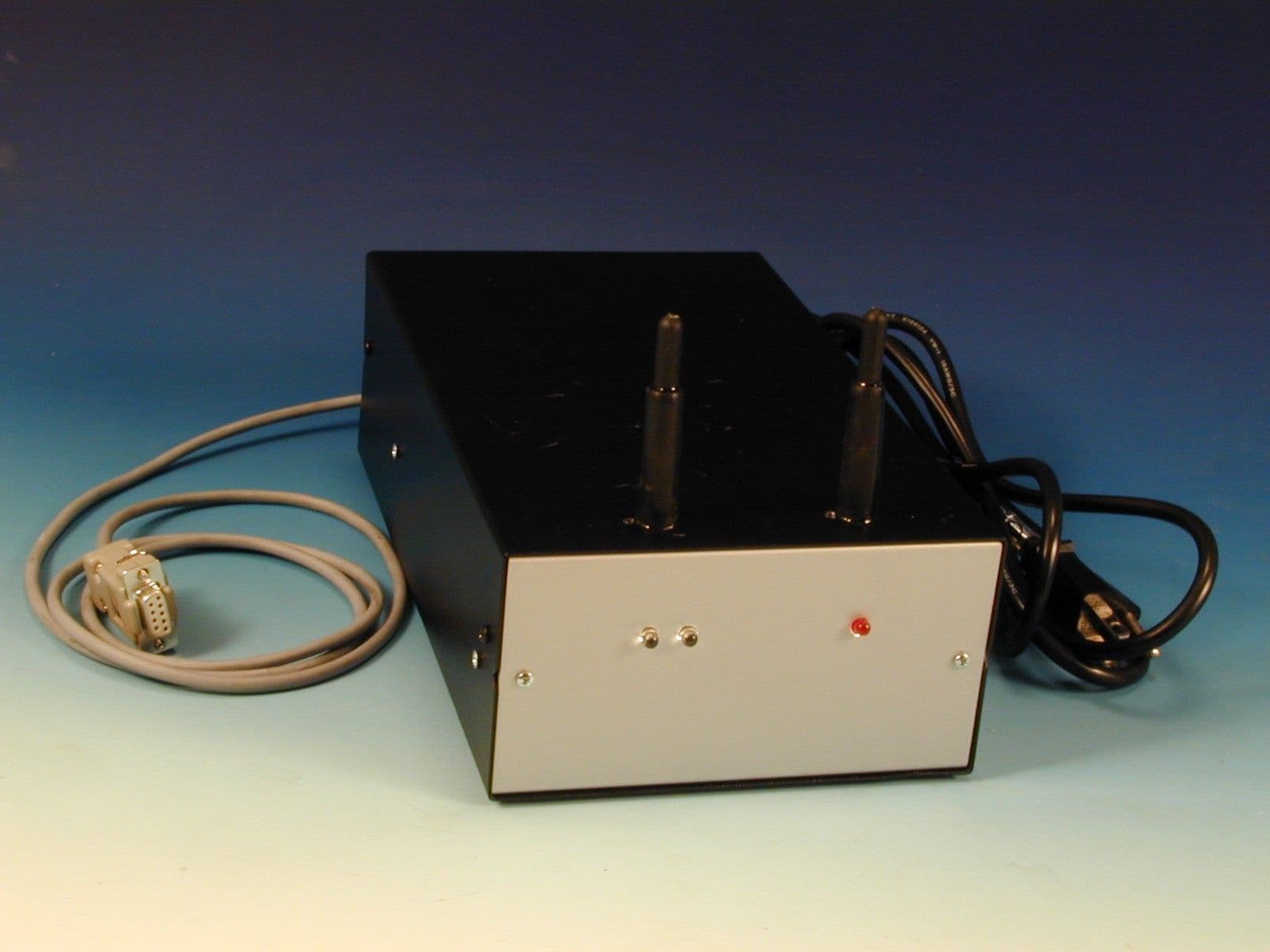
OM4TLVUCT4K
Feb 24, 2000Wireless Audience Response Controller
Equipment Class
DXX - Part 15 Low Power Communication Device Transmitter