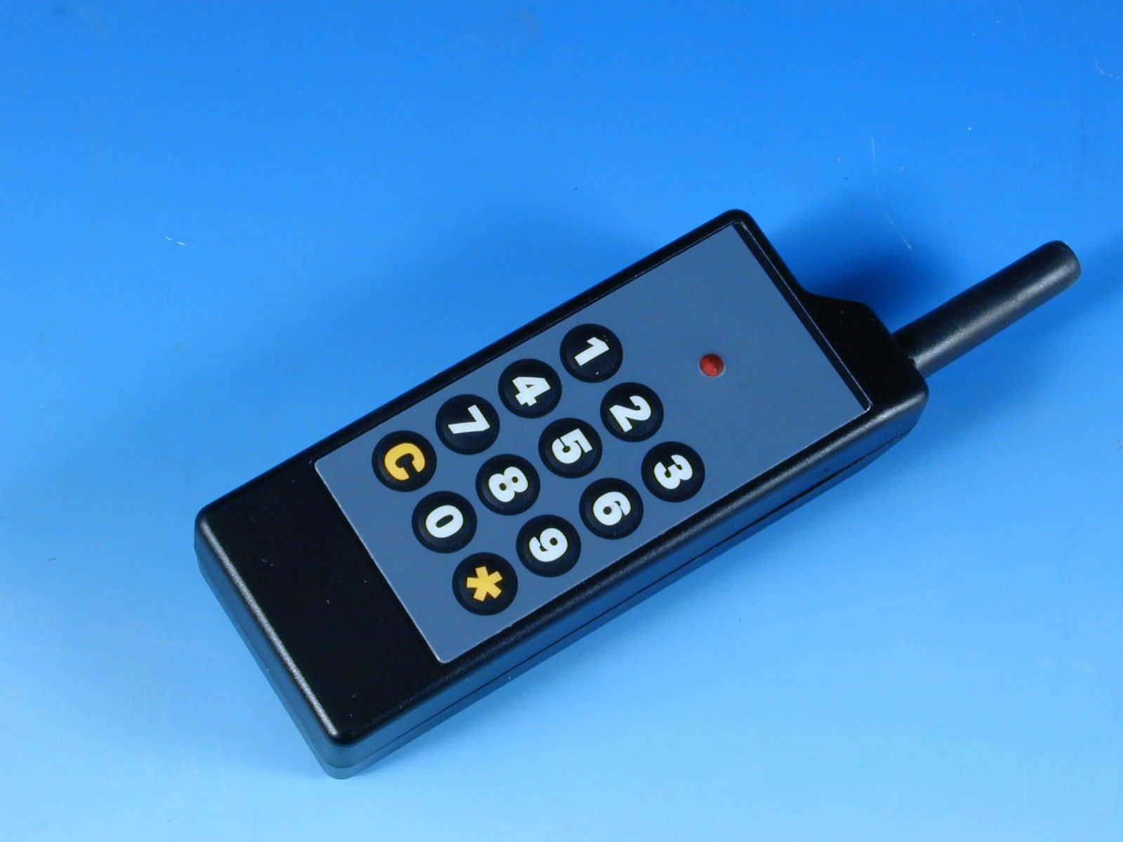
OM4TLVKPD4KKeypad for Televoter Wireless Audience
Logos Av Com S.r.l.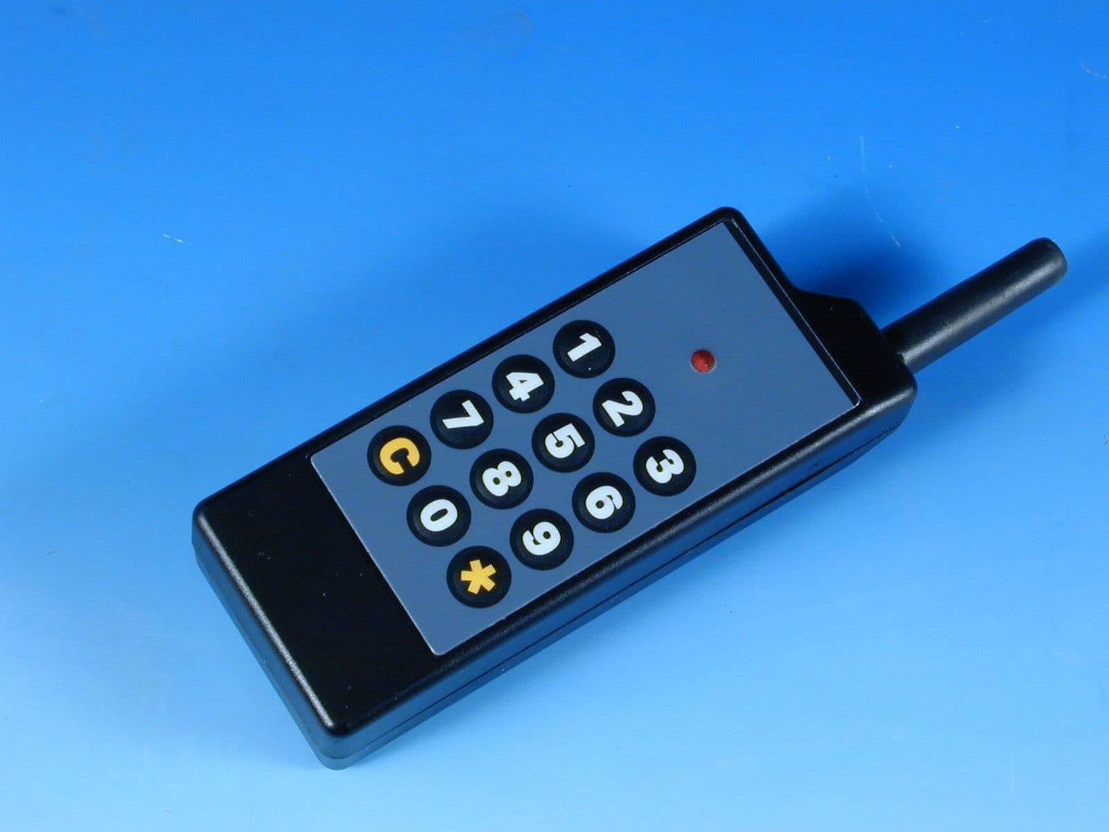
Click to zoom
Application Details
- Equipment Class
- DXX - Part 15 Low Power Communication Device Transmitter
- Date of Grant
- Feb 24, 2000
- Application Purpose
- Original Equipment
- Date of Application
- Feb 08, 2000
- Equipment Note
- Keypad for Televoter Wireless Audience
- Frequency Range
- 916.50000000 - 916.50000000
- Company
- Logos Av Com S.r.l.
- Country
- Italy
Documents & Files
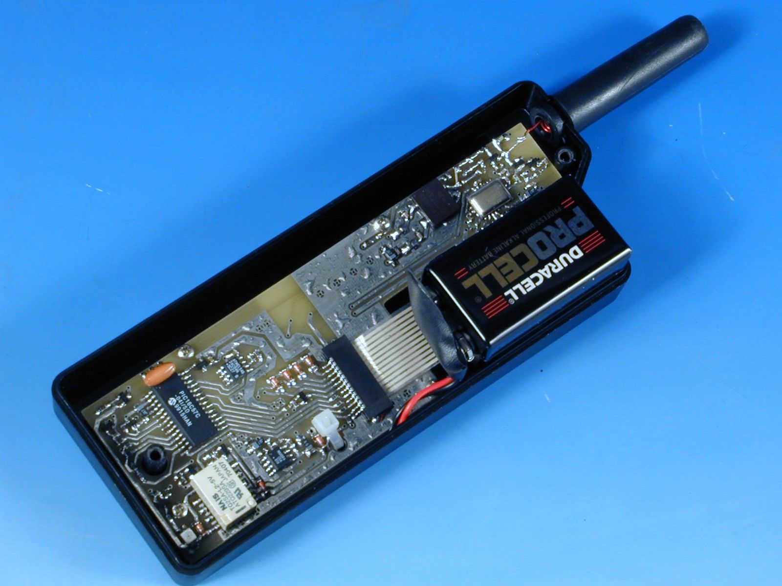
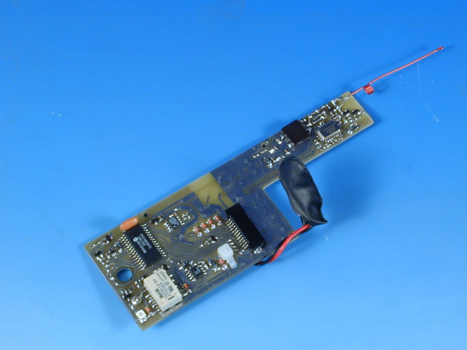
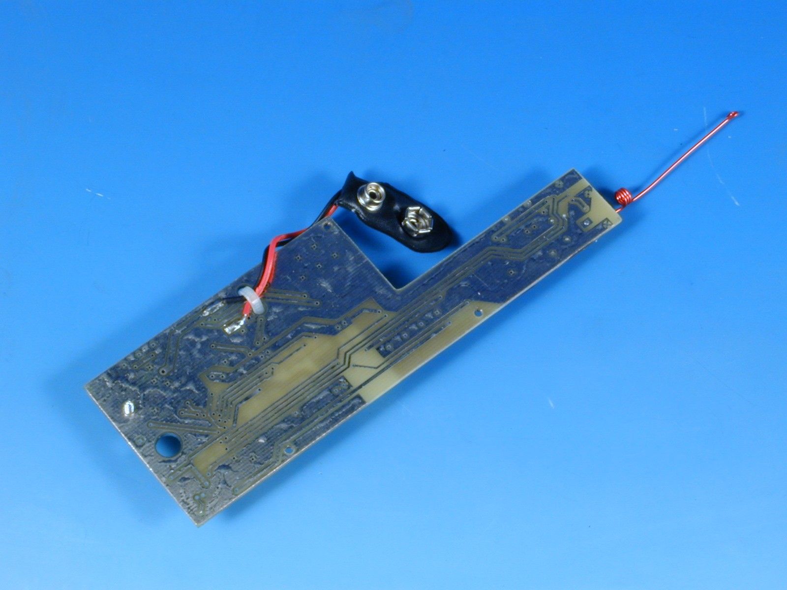
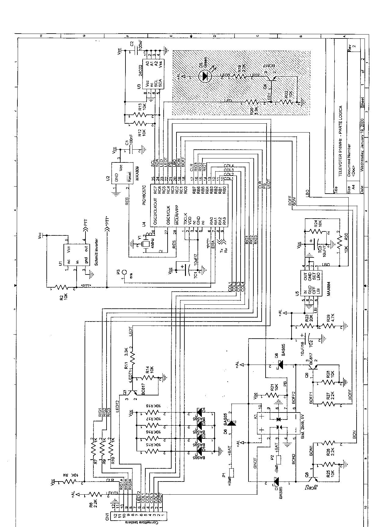
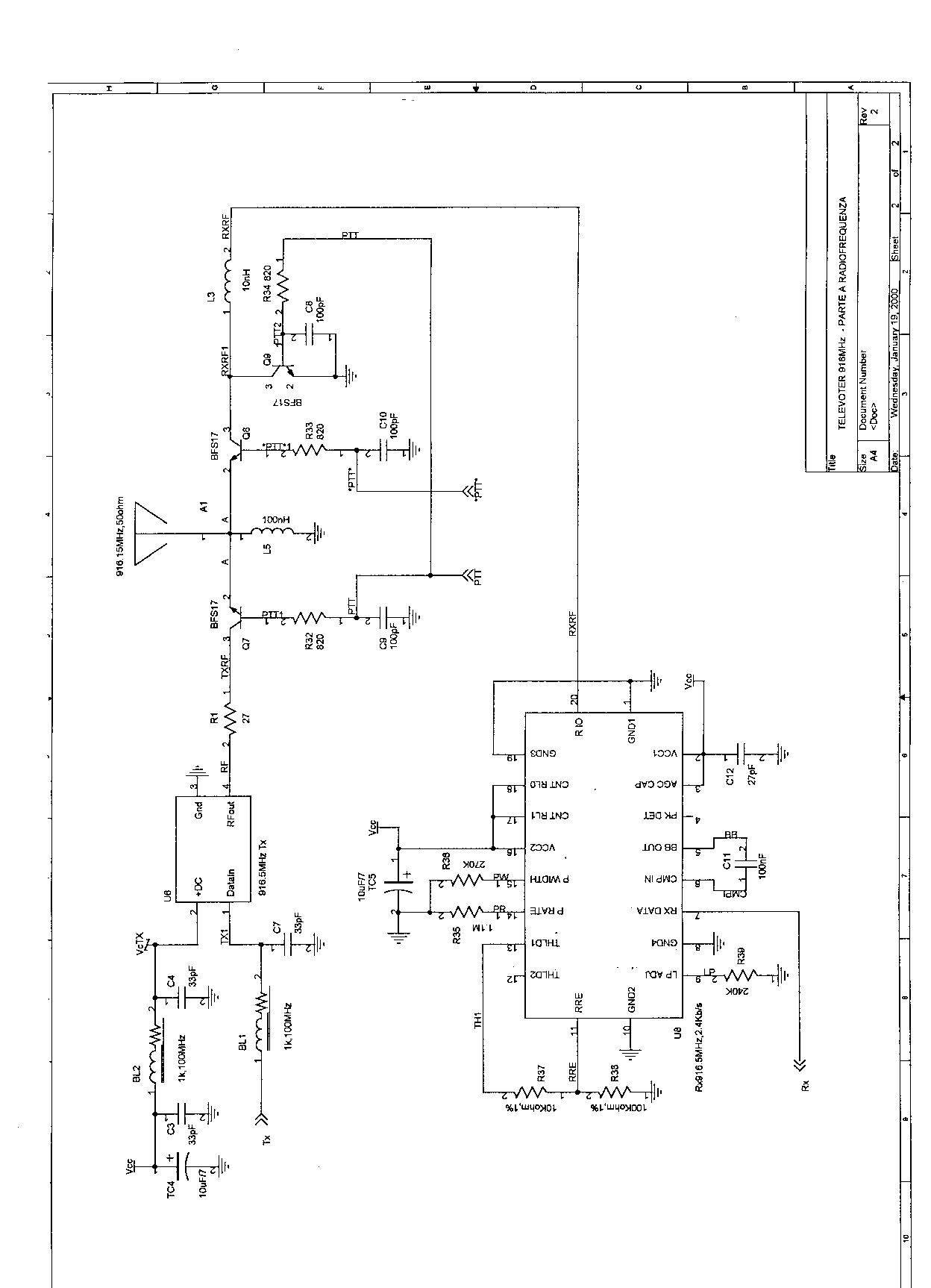
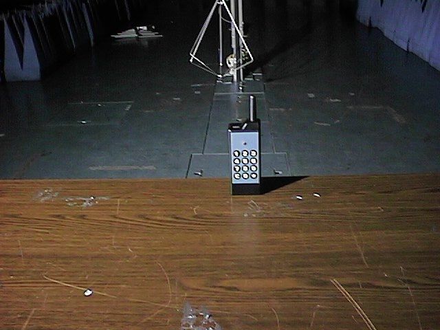
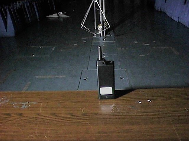
Document Text
Text extracted from the exhibit documents filed with the FCC. Open a document above to read the original.
Users Manual
Logos Av Com - Via Risorgimento, 22 - 48018 Faenza - Italy tel +39 0546 622 080 - fax +39 0546 622 090 - www.logosav.com Operating instructions The battery The voting keypad shall turn on by pressing any numerical key. As no "open" voting is occurring, the voting keypad shall turn off after a few seconds. Once the voting operations have started and you have to vote, you will see that the voting keypad, after pressing any key, will stay on for a longer time, i.e. for the whole duration of the voting operations. It shall turn off, automatically, only when the voting operations have finished. While the voting operations are "open", it is possible to change one's vote by pressing key C. The voting keypad shall turn off and you can enter your new vote. The voting keypad is fed by a 9 Volt alkali battery. The charge level of the battery can be checked by keeping to what follows. keep key C pressed and press (simultaneously) the Asterisk key; the red led shall blink and shall turn off after a few seconds: the battery is charged the red led is on: it is possible to vote, but the battery must be replaced within a short time the red led does not turn on: replace the battery by unscrewing the two screws behind the voting keypad.. When connecting and disconnecting the battery connector, make sure that the keyboard flat cable is not folded. Alkali batteries are more likely to discharge as a result of the passing of time than because of their usage for voting operations. It is therefore recommendable to replace them once a year. NOTE - This equipment has been tested and found to comply with the limits for a Class B digital device, pursuant to Part 15 of the FCC Rules. These limits are designed to provide reasonable protection against harmful interference in a residential installation. This equipment generates , uses and can radiate radio frequency energy and, if not installed and used in accordance with the instructions, may cause harmful interference to radio communications. However, there is no guarantee that interference will not occur in a particular installation. If this equipment does cause harmful interference to radio or television reception, which can be determined by turning the equipment off and on, the user is encouraged to try to correct the interference by one or more of the following measures: -- Reorient or relocate the receiving antenna. -- Increase the separation between the equipment and receiver. -- Connect the equipment into an outlet on a circuit different from that to which the receiver is connected. -- Consult the dealer or an experienced radio/TV technician for help. (FCC ID OM4 TLVKPD4K) CAUTION Changes or modifications not expressly approved by the manufacturer for compliance could void the user’s authority to operate the system.
Block Diagram
Fig. 4.1 - Block Diagram of the EUT Keyboar d and LED Micro with ceramic resonator and Logic DC\DC Imput 9Vcc Output 3.3Vcc Battery 9Vcc TX HX2000 916.5MHz RX RX6000 916.5MHz
Operational Description
Operational Description The P.C. software is used to communicate to the Televoter controller the kind of polling, the numbers of keyswitches enable, the numbers of voting keypads enable, and the numbers of the keyboard enable. The Televoter controller transmits the request of poll to the voting keypads and waits to the answer. This operation is made for every number of the voting keypads enable from the software of P.C. After receiving of all polls the Televoter controller transfers the polling to the P.C and goes to sleep mode. Its wake up is controlled from P.C when it needs to do a new polling. The voting keypads, after transmission of its data, close the transmitter. In this status the receiver is active.
Test Report
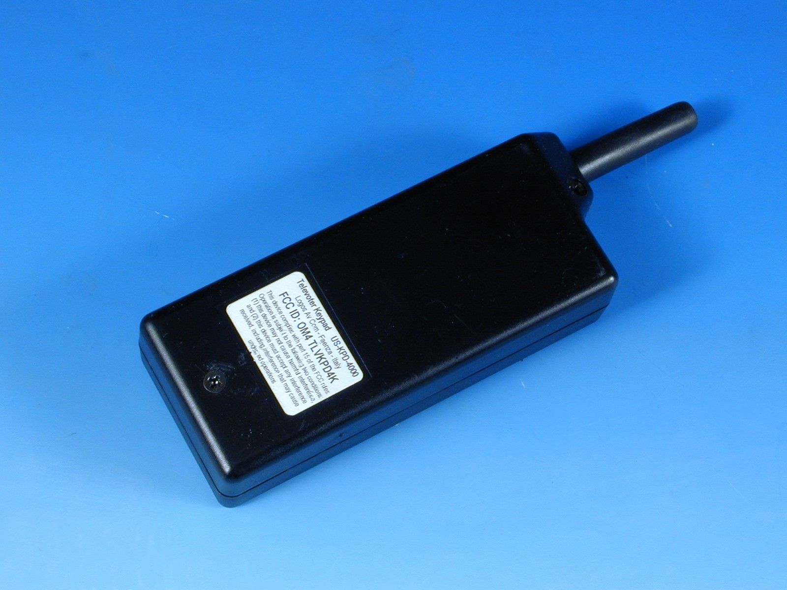
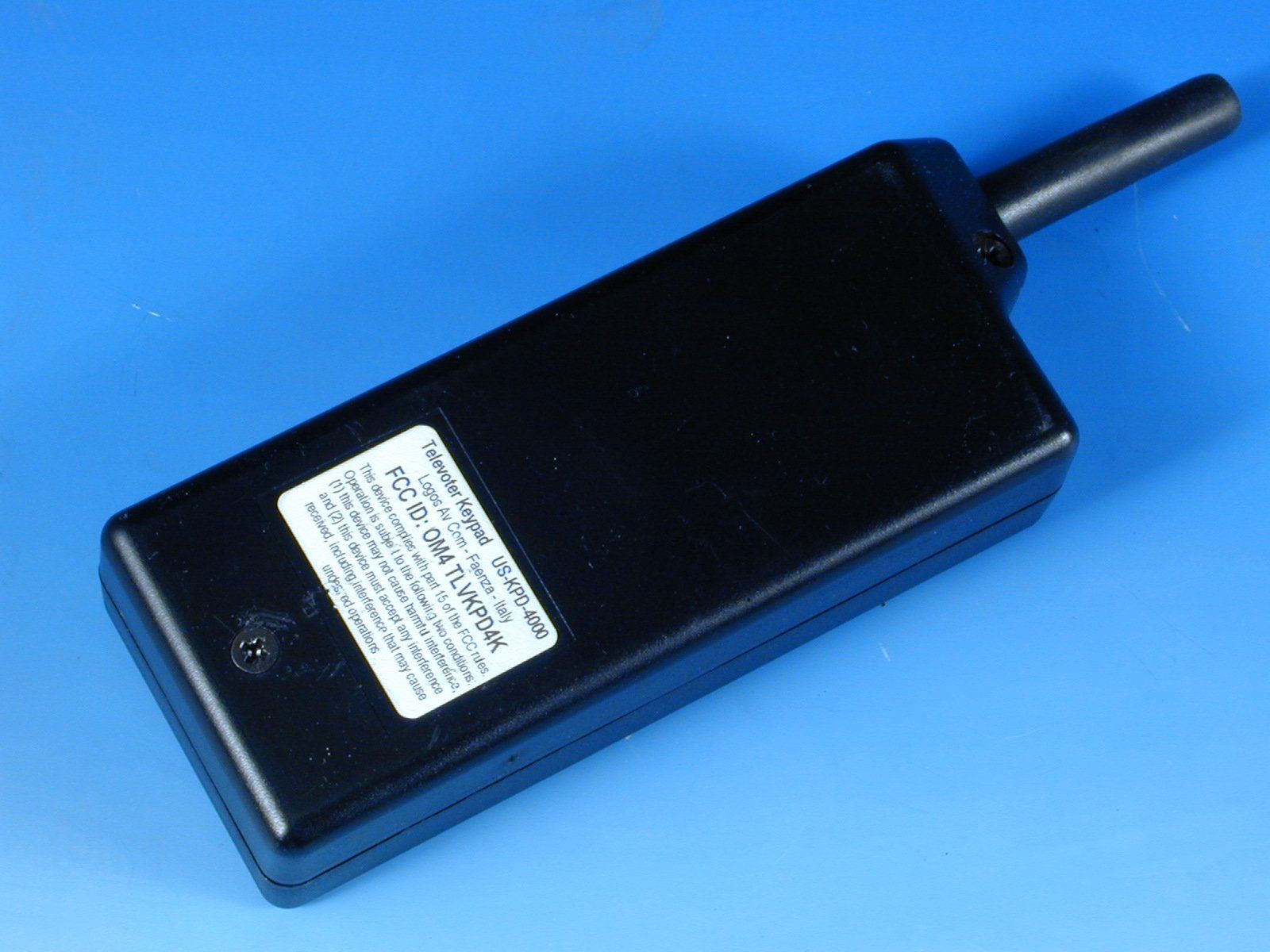
Test Report No. RD2000/009 FCC ID: OM4TLVKPD4K Date January 20 th , 2000 TÜV QSL 1/17 MEASUREMENT/TECHNICAL REPORT FCC Part 15 Section 15-209-15.249 Logos Av Com FCC ID: OM4TLVKPD4K January 20th, 2000 This report concerns (check one): Original grant __X__ Class II change____ Equipment type: TELEVOTER VOTING KEYPAD (ex.: computer, printer, modem, etc.) Deferred grant request per 47 CFR 0.457(d)(1)(ii)? yes _____ no __X__ If yes, defer until: ______________ date Company Name agrees to notify the Commission by ______________ date of the intended date of announcement of the product so that the grant can be issued on that date. Report prepared by: P.Antonio VELO Giuseppe MECCHIA TÜV QSL srl Via Montalenghe 12 10010 Scarmagno ( TO ) Italy Phone : 0125 - 525441 Phone : 0125 – 525440 Fax : 0125 – 525499 Test Report No. RD2000/009 FCC ID: OM4TLVKPD4K Date January 20 th , 2000 TÜV QSL 2/17 Table of Contents Page 1GENERAL INFORMATION ........................................................ 3 1.1 Product Description ........................................................ 3 1.2 Related Submittal(s)/Grant(s) .......................................... 3 1.3 Tested System Details ..................................................... 4 1.4 Test Methodology ............................................................ 5 1.5 Test Facility...................................................................... 5 1.6 Test Equipment List ......................................................... 5 2PRODUCT LABELING................................................................ 6 Figure 2.1 FCC ID Label ........................................................ 6 Figure 2.2 Location of the Label on EUT ............................... 7 3SYSTEM TEST CONFIGURATION ............................................ 8 3.1 Justification ...................................................................... 8 3.2 EUT Exercise Software.................................................... 8 3.3 Special Accessories......................................................... 9 3.4 Equipment Modifications.................................................. 9 3.5 Configuration of the Tested System ................................ 10 Figure 3.1 Configuration of the Tested System ...................... 10 4BLOCK DIAGRAM(S) OF THE EUT.. ......................................... 11 4.1 Block Diagram Description................................................ 11 Figure 4.1 Block Diagram of the EUT.. .................................. 12 5RADIATED MEASUREMENT PHOTOS ..................................... 13 7RADIATED EMISSION DATA..................................................... 14 7.2 Field Strength Calculation................................................ 15 8PHOTOS OF TESTED EUT ....................................................... 16 User Manual (Draft Edition) ............................................................... 17 Test Report No. RD2000/009 FCC ID: OM4TLVKPD4K Date January 20 th , 2000 TÜV QSL 3/17 1 GENERAL INFORMATION 1.1 Product Description EUT is a transceiver designed to be the keypad of a voting system; it works on 916.5 MHz frequency. The voting pad is composed of the following elements: a plastic container with antenna cover containing: - an electronic card with logic, transmit and receive sections (transceiver) and TX/RX antenna mounted (welded to PCB), - battery - Keyboard with 10 numeric keys (0-9) and 2 function keys. Each keypad has an identifying number from 1 to 4096. The pressing of a key records its reference number on internal memory. This equipment sends this number, identifying the pressed key, to the Televoter Controller (FCC ID: OM4 TLVUCT4K) when a voting session is opened, that is when the controller request data. The data is sent by air (radio TX mode), when the Controller carries out a polling operation on all present voters and calls up the identifying code of each voter. 1.2 Related Submittal(s)/Grant(s) FCC ID: OM4TLVUCT4K Test Report No. RD2000/009 FCC ID: OM4TLVKPD4K Date January 20 th , 2000 TÜV QSL 4/17 1.3 Tested System Details The FCC IDs for all equipment, plus descriptions of all cables used in the tested system (including inserted cards, which have grants) are: Model & Serial No. FCC IDDescriptionCable Descriptions US-KPD-4000 (1) s/n 0201 OM4TLVKPD4K Televoter Voting Keypad No cable provided Remotely connected to: US-UCT-4000 s/n EMC-99-0319 OM4TLVUCT4K Televoter controller Unshielded power cord Shielded signal cable Compaq Contura 420C s/n 7534HPE53700 CNT75MB2CCNotebookUnshielded power cord Shielded signal cables Series 2862 s/n E4532433329T NoneAC adapter for notebook Unshielded power cords DM 119 s/n 3031602 DYKDM119Printer, parallel I/FUnshielded power cord Shielded signal cable (1) EUT submitted for grant. Test Report No. RD2000/009 FCC ID: OM4TLVKPD4K Date January 20 th , 2000 TÜV QSL 5/17 1.4 Test Methodology Both conducted and radiated testing were performed according to the ANSI C63.4-1992 test procedures . Radiated testing was performed at an antenna to EUT distance of 3 meters. 1.5 Test Facility TÜV QSL test site No. 3 (semi-anechoic chamber) The semi-anechoic chamber test site and conducted measurement facility used to collect the radiated data are located at Via Montalenghe 12, Scarmagno, Italy. This site has been fully described in a report dated March 25, 1997 submitted to your office, and accepted in a letter dated August 4, 1997 (31040/SIT-1300F2). 1.6 Test equipment list: Test receiver/spectrum anal.HP 8568B+QP adapters/n 2601A02134 Biconical antennaTensor 4104s/n 2222 Log-periodic antenna Electro-metrix LPA-25s/n 1117 Spectrum analyzerHP 8562As/n 3043A05627 Horn antennaEMCO 3115s/n 3572 Test Report No. RD2000/009 FCC ID: OM4TLVKPD4K Date January 20 th , 2000 TÜV QSL 6/17 2 PRODUCT LABELING Figure 2.1 FCC ID Label See attached file: Televoter Keypad US-KPD-4000 Logos Av Com – Faenza – Italy FCC ID: OM4 TLVKPD4K This device complies with part 15 of the FCC rules. …
Text truncated - open the document above for the full version.
Contact Information
Applicant
Sergio Sangiorgi(President)
39-0546-622-080Fax: 39-0546-622-090
Test Firm
TUV QSL srlP. Velo
39-0125-529711Fax: 39-0125-711477
Technical Specifications
| # | Rule Parts | Frequency Range | Power Output |
|---|---|---|---|
| 1 | 15C | 916.5 MHz - 916.5 MHz | - |
Other Applications from Logos Av Com S.r.l.

OM4SLV-MA-US
Feb 29, 2004Televoter Master and Slave Antennas
Equipment Class
DXT - Part 15 Low Power Transceiver, Rx Verified
OM4TLV-MA-US
Feb 29, 2004Televoter Voting Keypad
Equipment Class
DXX - Part 15 Low Power Communication Device Transmitter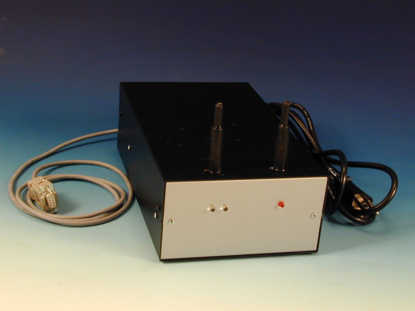
OM4TLVUCT4K
Feb 24, 2000Wireless Audience Response Controller
Equipment Class
DXX - Part 15 Low Power Communication Device Transmitter