OM4TLV-MA-USTelevoter Voting Keypad
Logos Av Com S.r.l.
Click to zoom
Application Details
- Equipment Class
- DXX - Part 15 Low Power Communication Device Transmitter
- Date of Grant
- Feb 29, 2004
- Application Purpose
- Original Equipment
- Date of Application
- Feb 29, 2004
- Equipment Note
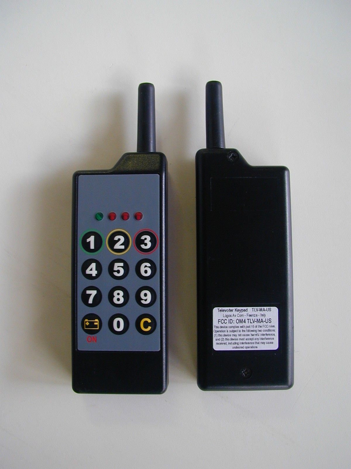
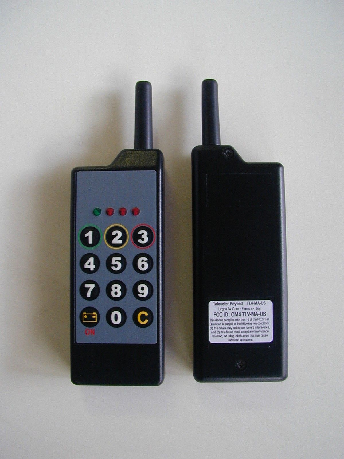
- Televoter Voting Keypad
- Frequency Range
- 916.50000000 - 916.50000000
- Company
- Logos Av Com S.r.l.
- Country
- Italy
Documents & Files
Document Text
Text extracted from the exhibit documents filed with the FCC. Open a document above to read the original.
Users Manual
Logos Av Com – Viale Risorgimento, 22 – 48018 Faenza – Italy Tel +39 0546 622 0809 – Fax +39 0546 622 090 - www.logosav.com Televoter Keypad mod. TLV-MA-US USER MANUAL Operating instruction (FCC ID: OM4TLV-MA-US) 1 – switching on - The voting keypad shall turn on by pressing the key with the icon “Battery ON”. The three red led will switch on indicating the full charge of the battery. If two or one led only are on, the battery is not fully charge; the pad can be used but a battery replacing must be planned. When the voter is switched on it goes in a “stand by” status, where it will stay during about four hours. 2- switching off – The pads can be switched off in three different way: 1- automatically at time expiration, four hours after the switching on 2- by the receiving of a radio signal “PAD OFF” sent by Slave Antennas 3- manually by keeping pressed the icon “Battery ON” and, contemporarily, the key C (Cancel) 3- stand by status refreshing – The stand by status is extended of other four hours when a special signal is sent by Slave antennas (follow the instruction of the software supplier) 4- Voting – When a signal VOTING OPEN is received, the pad switches on the green led, indicating the possibility to enter a choice, by pressing an allowed key in the keypad. Depending of the question, up to three choice are admitted. Each time a valid choice is entered one red led switches on and the data is recorded into the pad memory. When the voting is closed no more data could be entered and the pad keep his status up to the polling expiration. When the polling also is closed, the pad return in Stand by mode, (green led blinking) until a new voting is opened. 5- Choice modifying – Until a voting is opened the entered choice could be changed by pressing, first, the key C (cancel) and entering a new choice. 6- Battery replacing – Turn off the two screw from the back of the pad, unlock the battery connectors and connect a new battery. Do not use screw-drivers or other metallic object to unlock the connectors. At a new battery connections, all four led switch on simultaneously and switch off in progression. The battery is a standard alkaline 9V and his average life is about one year. 7 –Changes and modification – Changes or modification not expressly approved by the manufacturer for compliance could void the user’s authority to operate the system. NOTE . This equipment has been tested and found to comply with the limits for Class B digital device, pursuant to part 15 of the FCC Rules. These limits are designed to provide reasonable protection against harmful interface in a residential installation. This equipment generates, uses and can radiate radio frequency energy and, if not installed and used in accordance with this instructions, may cause harmful interface to radio communication. However, there is no guarantee that interface will not occur in a particular installation. If this equipment does cause harmful interface to radio or television reception, which can be determined by turning this equipment off and on, the user is encouraged to try to correct the interference by one or more of the following measures: - Reorient or relocate the receiving antenna. - Increase the separation between the equipment and receiver. - Connect the equipment into an outlet on a circuit different from that to which the receiver is connected. - Consult the dealer or an experienced radio/TV technician for help.
ID Label/Location Info
Televoter Keypad TLV–MA-US Logos Av Com – Faenza – Italy FCC ID: OM4 TLV–MA-US This device complies with part 15 of the FCC rules. Operation is subjected to the following two conditions: (1)this device may not cause harmful interference and (2) this device must accept any interference received, including interference that may cause undesired operations
Operational Description
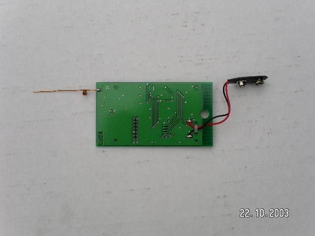
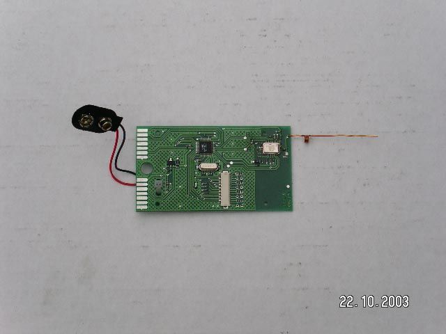
FCCID: OM4TLV-MA-US Operational Description 1.1 Product description EUT is a transceiver designed to be the keypad of a voting system. The voting pad is composed of the following elements: • A plastic container with antenna cover containing: • an electronic card with logic, transmit and receive section (transceiver) and TX/RX antenna mounted (welded on PCB) • battery • keyboard with 10 numeric keys (0-9) and 2 function keys • 1 green led and 3 red led Each keyboard have an identifying number from 1 to 16.383, divided in 32 block of 512. 1.1.1 Operational description A command, sent by slaves antennas to all the pads present in the area, open the voting. After this moment, the pad owners are allowed, by pressing a key, to record their choice into an internal memory of the voting pad. When a proper command is received from the slave antennas (FCC IC:OM4SLV-MA-US) the voting pads, pertaining to the requested block, send, one after the other, the data of the recorded choice to the slave antennas, which are, at the moment, switched in receiving mode. The data are sent by air (radio TX mode) on the frequency of 916.50 MHz. When collected, the data of the first block, are sent, from the slave antennas to the Master unit (MST-MA-US), by cable on a RS 485 line, and from the Master Unit to the PC, through the RS232 port for their processing and displaying. Immediately, the system will poll the further blocks present in the area. 1.1.2 Modulation upon the carrier: - only one frequency is used: 916,50 MHz - modulation type: AFK - data rate max: 56 Kbps
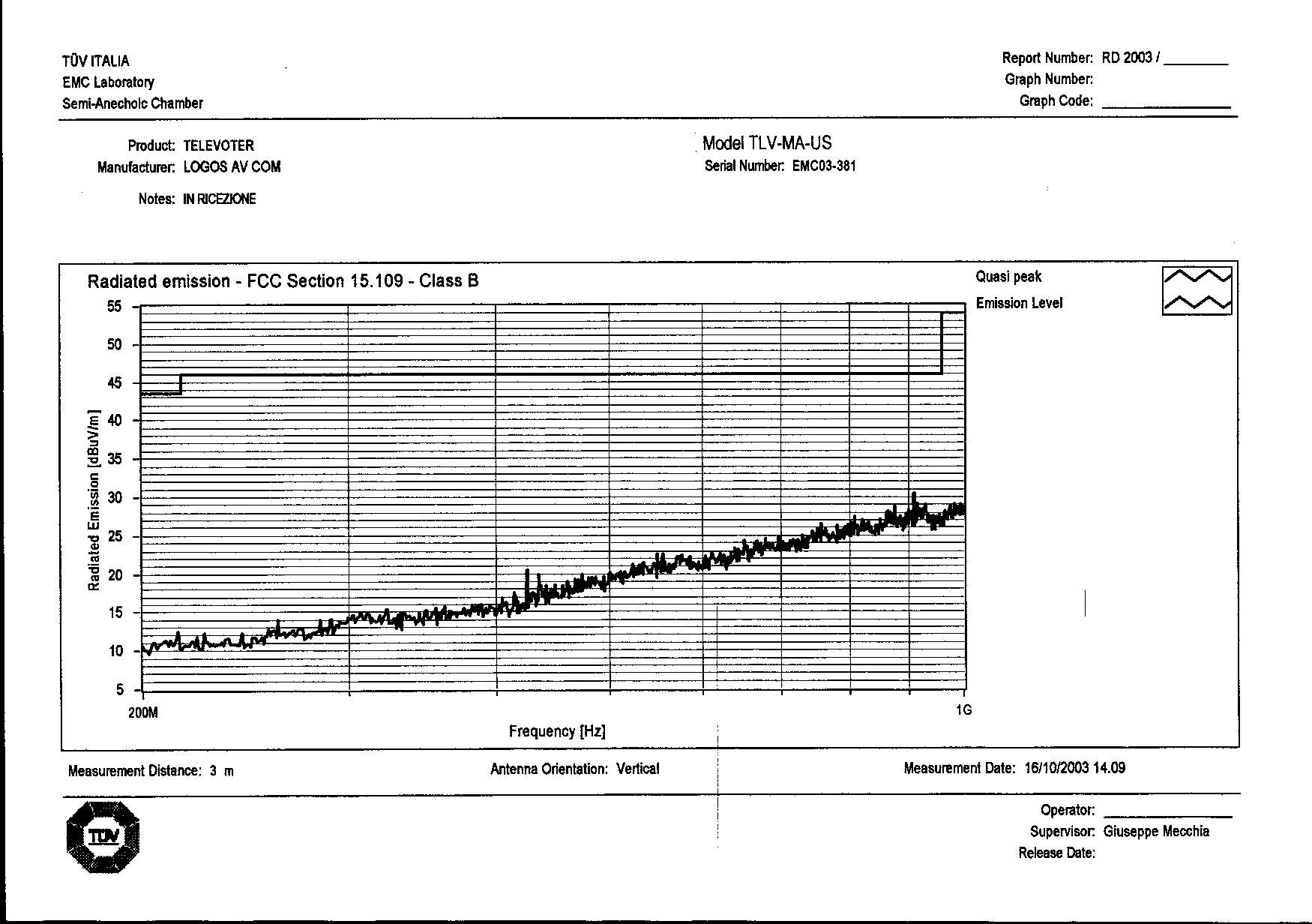
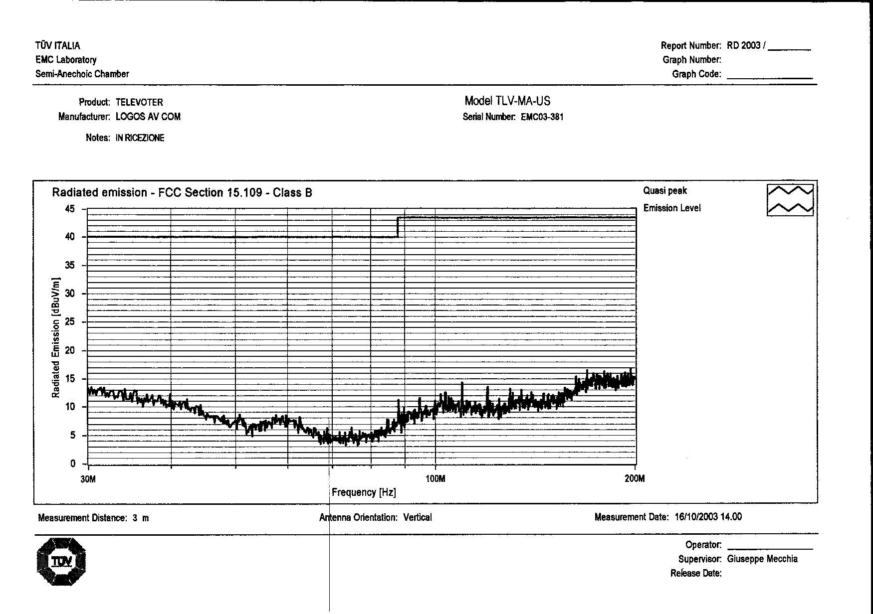
Test Report
Test Report No. RD2003/210-bis FCC ID: OM4TLV-MA-US Date November 24 th , 2003 TÜV ITALIA 1/16 MEASUREMENT/TECHNICAL REPORT FCC Part 15 Sections 15.209, 15.249 Logos Av Com FCC ID: OM4TLV-MA-US November 30 th , 2003 This report concerns (check one): Original grant __X__ Class II change____ Equipment type: TELEVOTER VOTING KEYPAD (ex.: computer, printer, modem, etc.) Deferred grant request per 47 CFR 0.457(d)(1)(ii)? yes _____ no __X__ If yes, defer until: ______________ date Company Name agrees to notify the Commission by ______________ Date of the intended date of announcement of the product so that the grant can be issued on that date. Report prepared by: Giuseppe MECCHIA TÜV ITALIA srl Via Montalenghe 12 10010 Scarmagno ( TO ) Italy Phone : +39-0125-636911 Fax : +39-0125-636999 Test Report No. RD2003/210-bis FCC ID: OM4TLV-MA-US Date November 24 th , 2003 TÜV ITALIA 2/16 Table of Contents Page 1GENERAL INFORMATION ................................................................ 3 1.1 Product Description ................................................................ 3 1.1.1Operational description ....................................... .3 1.1.2Modulation upon the carrier .............................. ... 3 1.2 Related Submittal(s)/Grant(s)................................................. 3 1.3 Tested System Details............................................................ 4 1.4 Test Methodology..................................................................... 5 1.5 Test Facility............................................................................... 5 1.6 Test Equipment List................................................................. 5 2PRODUCT LABELING........................................................................ 6 3SYSTEM TEST CONFIGURATION.................................................... 7 3.1 Justification............................................................................... 7 3.2 EUT Exercise Software........................................................... 7 3.3 Special Accessories................................................................ 8 3.4 Equipment Modifications......................................................... 8 3.5 Configuration of the Tested System....................................... 9 Figure 3.1 Configuration of the Tested System............................ 9 4BLOCK DIAGRAM(S) OF THE EUT..................................................10 4.1 Block Diagram Description......................................................10 Figure 4.1 Block Diagram of the EUT..........................................11 5RADIATED MEASUREMENT PHOTOS...........................................12 7RADIATED EMISSION DATA............................................................13 7.2 Field Strength Calculation.......................................................14 8PHOTOS OF TESTED EUT...............................................................15 User Manual..................................................................................................16 Test Report No. RD2003/210-bis FCC ID: OM4TLV-MA-US Date November 24 th , 2003 TÜV ITALIA 3/16 1 GENERAL INFORMATION 1.1 Product description EUT is a transceiver designed to be the keypad of a voting system. The voting pad is composed of the following elements: • A plastic container with antenna cover containing: • an electronic card with logic, transmit and receive section (transceiver) and TX/RX antenna mounted (welded on PCB) • battery • keyboard with 10 numeric keys (0-9) and 2 function keys • 1 green led and 3 red led Each keyboard have an identifying number from 1 to 16.383, divided in 32 block of 512. 1.1.1 Operational description A command, sent by slaves antennas to all the pads present in the area, open the voting. After this moment, the pad owners are allowed, by pressing a key, to record their choice into an internal memory of the voting pad. When a proper command is received from the slave antennas (FCC IC:OM4SLV-MA- US) the voting pads, pertaining to the requested block, send, one after the other, the data of the recorded choice to the slave antennas, which are, at the moment, switched in receiving mode. The data are sent by air (radio TX mode) on the frequency of 916.50 MHz. When collected, the data of the first block, are sent, from the slave antennas to the Master unit (MST-MA-US), by cable on a RS 485 line, and from the Master Unit to the PC, through the RS232 port for their processing and displaying. Immediately, the system will poll the further blocks present in the area. 1.1.2 Modulation upon the carrier: - only one frequency is used: 916,50 MHz - modulation type: AFK - data rate max: 56 Kbps 1.2 Related Submittal(s)/Grant(s) FCC ID: OM4SLV-MA-US Test Report No. RD2003/210-bis FCC ID: OM4TLV-MA-US Date November 24 th , 2003 TÜV ITALIA 4/16 1.3 Tested System Details The FCC IDs for all equipment, plus descriptions of all cables used in the tested system (including inserted cards, which have grants) are: Model & Serial No. FCC IDDescriptionCable Descriptions TLV-MA-US (1) s/n EMC03-381 OM4TLV-MA-USTelevoter Voting Keypad No cable provided Remotely connected to: SLV-MA-US s/n EMC03-380 OM4SLV-MA-USTelevoter slave RS 485 I/F Shielded signal/power cable MST-MA-US s/n EMC03-379 None Verified unit Televoter Master RS 232 I/F Unshielded power cord Shielded signal cables Hitek power Mod. 1AA12018 S/n / nonePower supply for Master Unshielded power cords Dell Dimension 4100 mod. MMS s/n FN9010J D.o.C.Personal ComputerUnshielded power cord Shielded signal cables Highscreen mod. MS1990E type J91B s/n 8016001183 AMPJ91BMonitorUnshielded power cord Shielded signal cable Dell SK 8000 S/n CN-037JMY- 38844-08N-J491 D.o.C.KeyboardShielded signal cable Microsoft Intellimouse S/n 4526477-2 D.o.C.MouseShielded signal cable DM 119 s/n 3031602 DYKDM119Printer, parallel I/FUnshielded power cord Shielded signal cable (1) EUT submitted for grant. Test Report No. RD2003/210-bis FCC …
Text truncated - open the document above for the full version.
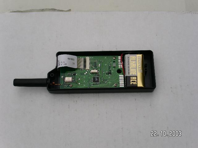
Test Setup Photos
OM4TLV-MA-US - TEST SET-UP PHOTOS
Contact Information
Applicant
Sergio Sangiorgi(President)
39-0546-622-080Fax: 39-0546-622-090
Technical Contact
AmericanTCBWilliam H Graff
[email protected]703 847 4700
6731 Whittier Avenue · Mclean, Virginia · United States
Test Firm
TUV ItaliaGiuseppe Mecchia
Technical Specifications
| # | Rule Parts | Frequency Range | Power Output |
|---|---|---|---|
| 1 | 15C | 916.5 MHz - 916.5 MHz | - |
Other Applications from Logos Av Com S.r.l.

OM4SLV-MA-US
Feb 29, 2004Televoter Master and Slave Antennas
Equipment Class
DXT - Part 15 Low Power Transceiver, Rx Verified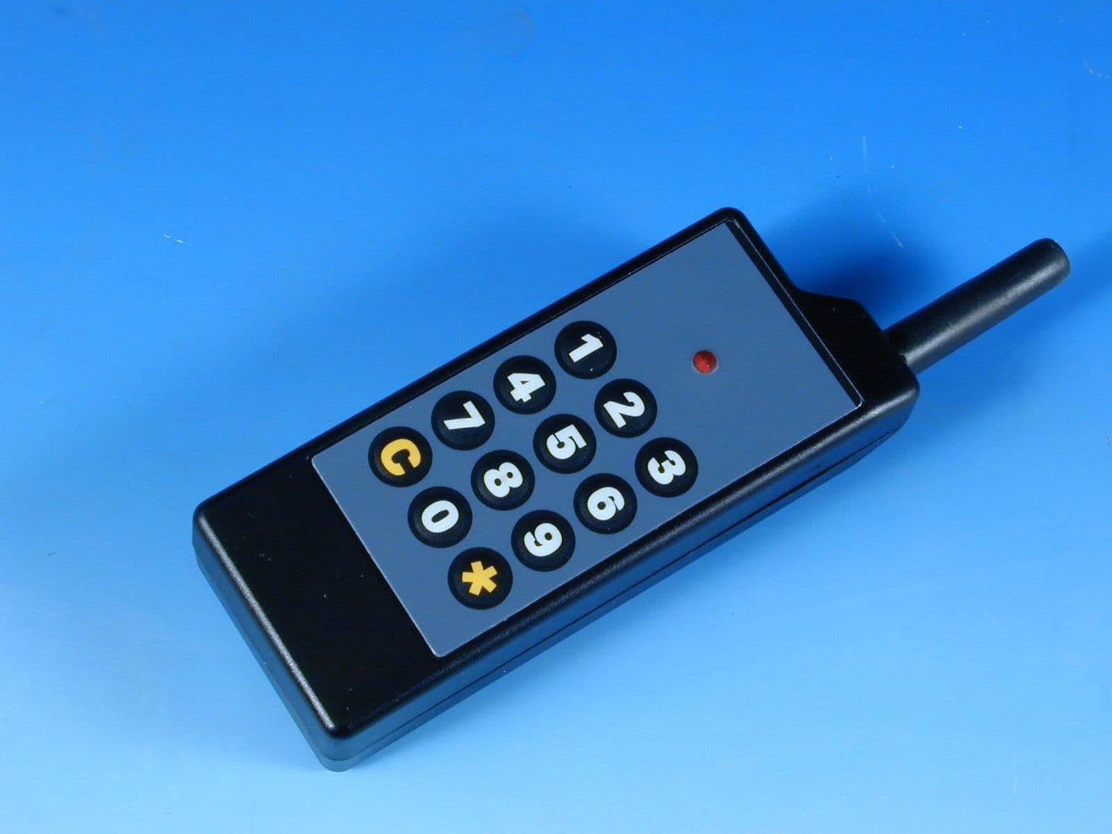
OM4TLVKPD4K
Feb 24, 2000Keypad for Televoter Wireless Audience
Equipment Class
DXX - Part 15 Low Power Communication Device Transmitter
OM4TLVUCT4K
Feb 24, 2000Wireless Audience Response Controller
Equipment Class
DXX - Part 15 Low Power Communication Device Transmitter