ON3MPSDT2Proximity Sensor TX
Prastel S.p.A.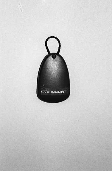
Click to zoom
Application Details
- Equipment Class
- DXX - Part 15 Low Power Communication Device Transmitter
- Date of Grant
- Feb 02, 2000
- Application Purpose
- Original Equipment
- Date of Application
- Nov 07, 1999
- Equipment Note
- Proximity Sensor TX
- Frequency Range
- 433.92000000 - 433.92000000
- Company
- Prastel S.p.A.
- Country
- Italy
Documents & Files
Document Text
Text extracted from the exhibit documents filed with the FCC. Open a document above to read the original.
Users Manual
MPSDT2 ENGLISH MPSDT2_V0.doc Member of:Associated CAUTION FOR THE USER Any change or modification of the product is forbidden if not expressly approved by the manufacturer 0. DESCRIPTION MPSDT2 is a radio transmitter used with radio receivers of the Multipass and Roll series; furthermore it is provided with a passive transponder (frequency 125 kHz) which permits to operate with a proximity reader used in access control applications. It has two pushbuttons being capable to activate two different output channels on a radio receiver working with the same code and the same operating frequency. It can also activate the output of a proximity reader by means of transponder. It works on 433.920 MHz frequency regulated by a SAW oscillator (radio section) and on 125 kHz frequency (transponder section). It is provided with an integral antenna. It is not possible to transmit continously with MPSDT2. 1. APPLICATIONS It can be used in remote control applications as door opener and in control access applications. 2. TECHNICAL FEATURES Transmission frequency433.92 MHz (radio section) – 125 kHz (transponder section) Type of coderolling code No. Of channels2 (radio) + 1 (transponder) Power supply6V (two 3 V lithium battery) Power consumptionNegligible when not operating, 15mA for transmission Duration of transmission2 sec (radio transmission) Signalling devicesred LED MPSDT2 ENGLISH MPSDT2_V0.doc Member of:Associated 3. HOW TO PROCEED WHEN CHANGING THE BATTERY HOW TO CHANGE THE BATTERIES: • Loosen screw «A» as shown in Fig. 1. • Open the remote control. • Remove the batteries handling them as shown in Fig. 2. • Fit new batteries taking care of aligning polarity correctly (see Fig. 4). LITHIUM BATTERY 3V B FCC ID: ON3MPSDT2 This device complies with part 15 of the FCC Rules. Operation is subject to the following two conditions: (1) this device may not cause harmful interference, and (2) this device must accept any interference received, including interference that may cause undesired operation. This equipment has been tested and found to comply with the limits for a Class B digital device, pursuant to Part 15 of the FCC Rules. These limits are designed to provide reasonable protection against harmful interference in a residential installation. This equipment generates, uses and can radiate radio frequency energy and, if not installed and used in accordance with the instructions, may cause harmful interference to radio communications. However, there is no guarantee that interference will not occur in a particular installation. If this equipment does cause harmful interference to radio or television reception, which can be determined by turning the equipment off and on, the user is encouraged to try to correct the interference by one or more of the following measures: -Reorient or relocate the receiving antenna. -Increase the separation between the equipment and receiver. -Connect the equipment into an outlet on a circuit different from that to which the receiver is connected. -Consult the dealer or an experienced radio/TV technician for help. FIG. 1 FIG. 4 FIG. 2/1 A FIG. 2
Block Diagram
FCC ID : ON3MPSDT2 Block diagram Pag. 1 BLOCK DIAGRAM(S) OF THE EUT Block Diagram Description The Controller Board of the EUT is provided with: SAW oscillator SAW1= 433.920 MHz Transponder Nil=125 kHz FCC ID : ON3MPSDT2 Block diagram Pag. 2 Fig. 1 - Block Diagram of the EUT
External Photos
FCC ID : ON3MPSDT2 External photos Pag. 1 Fig. 1 Overall front view FCC ID : ON3MPSDT2 External photos Pag. 2 Fig. 2 Overall rear view
ID Label/Location Info
FCC ID : ON3MPSDT2 ID Label Pag. 1 PRODUCT LABELING Figure 1 FCC ID Label FCC ID: ON3MPSDT2 FCC ID : ON3MPSDT2 ID Label Pag. 2 Figure 2 Location of the Label on EUT
Internal Photos
FCC ID : ON3MPSDT2 Internal photos Pag. 1 Fig. 1 Rear view with cover removed FCC ID : ON3MPSDT2 Internal photos Pag. 2 Fig. 2 Controller Board - Components side FCC ID : ON3MPSDT2 Internal photos Pag. 3 Fig. 3 Controller Board - Foil side
Operational Description
FCC ID : ON3MPSDT2 Operational description Pag. 1 GENERAL INFORMATION Product Description EUT is a radio transmitter used with radio receivers of the Multipass and Roll series; furthermore it is provided with a passive transponder (frequency 125 kHz) which permits to operate with a proximity reader used in access control applications. It has two pushbuttons being capable of activating two different channels on a radio receiver working with the same code and the same operating frequency. It works on 433.920 MHz frequency regulated by a saw oscillator (radio section) and on 125 kHz (transponder section). It is provided with a built in antenna and it does not permit a continuous transmission (operation is limited to about two seconds). The EUT without transponder has been previously approved, reference to our test report RD 99/153 of October 13,1999 – FCC-ID: ON3MPSTP2E B.
Parts List/Tune Up Info
FCC ID : ON3MPSDT2 Part list Pag. 1 MPSDT2 part list |----------------------------------------------------------------------------------------------------------------------------------------------------------| |Bill Of Materials for L9042B2.sch on Wed Jul 21 17:23:58 1999 | |----------------------------------------------------------------------------------------------------------------------------------------------------------| |Item|Qty |Ref. |Prastel Code |Name |Value |Tol. |Description | |----+-----+-----------------------------+----------------+--------------------+------------+------+-------------------------------------------------------| |1 |1 |J1 | | | | |Soldering Strip 5P 1.27 | |2 |1 |JP1 | |JP2 | | |Wire Jumper | |3 |1 |A2 | |Manifacturing | | |Manufacturing | |4 |1 |A1 | |NOTE | | |Row Pitch, Dimension See Sample | |5 |1 |R1 | |RSMD OPT | |5% |Resistor 0805 SMT | |6 |2 |P1-2 | | | | |Horizontal Pushbutton | |7 |1 |B2 |BAT6VL | |6V | | | |8 |1 |C8 |C10NCS |CSMD |10nF |Z5U |Ceramic Capacitor 0805 SMT | |9 |1 |C9 |C1M0V16S |CSMD |1MF16V | |Tantalum Capacitor CaseA SMT | |10 |2 |C3 C7 |C1N0CS |CSMD |1nF |Z5U |Ceramic Capacitor 0805 SMT | |11 |1 |C2 |C1P0CS |CSMD |1pF |NP0 |Ceramic Capacitor 0805 SMT | |12 |1 |C5 |C1P5CS |CSMD |1p5F |NP0 |Ceramic Capacitor 0805 SMT | |13 |1 |C1 |C1T03C2S |TZBX4Z030AE110 |1.4-3pF | |Trimmer Capacitor SMT | |14 |1 |C4 |C3P3CS |CSMD |3p3F |NP0 |Ceramic Capacitor 0805 SMT | |15 |1 |C6 |C4P7CS |CSMD |4p7F |NP0 |Ceramic Capacitor 0805 SMT | |16 |1 |Z1 |CSL391-2 |L391-2 |1mm/35um | |PCB Double Side | |17 |1 |D1 |DBAS16 |BAS16 | | |Signal Diode SOT23 SMT | |18 |1 |LD1 |DLEDRS2 |LHT774M | | |SMT-Top-Led Reverse Gullwing Hyper-Red | |19 |1 |L1 |I1UHST5 |B82422-A1102-M |1MH |5% |Inductor SIMID02-04 SMT | |20 |1 |L2 |I27NHST5 | |27nH |5% |Inductor SIMID02-04 SMT | |21 |1 |U1 |ICPL886AP1 |PL886A | | |8 Bit CMOS Microcontroller | |22 |1 |B1 |LAMBAT5 (x2) |ATTBAT6V | | |Battery Connector ROLLT2 | |23 |1 |P3 |PMET01 |SKHUAB | | |Horizontal Pushbutton SMT | |24 |1 |R5 |R0R0S |RSMD |0 Ohm |5% |Resistor 0805 SMT | |25 |2 |R2 R8 |R10KS |RSMD |10K |5% |Resistor 0805 SMT | |26 |1 |R7 |R1K0S |RSMD |1K |5% |Resistor 0805 SMT | |27 |1 |R6 |R47KS |RSMD |47K |5% |Resistor 0805 SMT | |28 |1 |SAW1 |RISSAW3S1 |R02101A | | |SAW Resonator 433.92 MHz | |29 |1 |R3 |RK56S |RSMD |560 |5% |Resistor 0805 SMT | |30 |1 |R9 |RM10S |RSMD |100K |5% |Resistor 0805 SMT | |31 |1 |R4 |RM68S |RSMD |680K |5% |Resistor 0805 SMT | |32 |1 |Q3 |TBC847C |BC847C | | |NPN Small Signal Transistor SOT23 SMT | |33 |2 |Q1-2 |TBFR93A |BFR93A | | |NPN Small Signal Transistor SOT23 SMT |34 |1 | |TRASP2 | | | |Transponder 125 kHz HID |------------------------------------------------------------------------------- ---------------------------------------------------------------------------|
Schematics
FCC ID : ON3MPSDT2 Schematics Pag. 1 MPSDT2 electrical scheme FCC ID : ON3MPSDT2 Schematics Pag. 2 MPSDT2 circuit layout FCC ID : ON3MPSDT2 Schematics Pag. 3 FCC ID : ON3MPSDT2 Schematics Pag. 4 FCC ID : ON3MPSDT2 Schematics Pag. 5 FCC ID : ON3MPSDT2 Schematics Pag. 6 MPSDT2 block diagram
Test Report
Test Report No. RD99/168 FCC ID: ON3MPSDT2 Date November 3rd, 1999 TÜV QSL 1/25 MEASUREMENT/TECHNICAL REPORT PRASTEL FCC ID: ON3MPSDT2 November 3rd, 1999 This report concerns (check one): Original grant __X__ Class II change____ Equipment type: RADIO TRANSMITTER (ex.: computer, printer, modem, etc.) Deferred grant request per 47 CFR 0.457(d)(1)(ii)? yes _____ no __X__ If yes, defer until: ______________ date Company Name agrees to notify the Commission by ______________ date of the intended date of announcement of the product so that the grant can be issued on that date. Report prepared by: P.Antonio VELO Giuseppe MECCHIA TÜV QSL srl Via Montalenghe 8 10010 Scarmagno ( TO ) Italy Phone : 0125 - 525441 Phone : 0125 – 525440 Fax : 0125 – 525499 Test Report No. RD99/168 FCC ID: ON3MPSDT2 Date November 3rd, 1999 TÜV QSL 2/25 Table of Contents Page 1GENERAL INFORMATION ........................................................ 3 1.1 Product Description ......................................................... 3 1.2 Related Submittal(s)/Grant(s) .......................................... 3 1.3 Tested System Details ..................................................... 4 1.4 Test Methodology ............................................................ 5 1.5 Test Facility...................................................................... 5 1.6 Test Equipment List ......................................................... 5 2PRODUCT LABELING ................................................................ 6 Figure 2.1 FCC ID Label ........................................................ 6 Figure 2.2 Location of the Label on EUT ............................... 7 3SYSTEM TEST CONFIGURATION............................................. 8 3.1 Justification ...................................................................... 8 3.2 EUT Exercise Software .................................................... 9 3.3 Special Accessories......................................................... 9 3.4 Equipment Modifications .................................................. 9 3.5 Configuration of the Tested System.................................10 Figure 3.1 Configuration of the Tested System ......................10 4BLOCK DIAGRAM(S) OF THE EUT............................................11 4.1 Block Diagram Description................................................11 Figure 4.1 Block Diagram of the EUT.. ..................................12 5CONDUCTED AND RADIATED MEASUREMENT PHOTOS .....13 6CONDUCTED EMISSION DATA.................................................14 7RADIATED EMISSION DATA .....................................................15 7.2 Field Strength Calculation................................................17 8PHOTOS OF TESTED EUT ........................................................18-24 User Manual (Draft Edition) ............................................................... 25-Attached Test Report No. RD99/168 FCC ID: ON3MPSDT2 Date November 3rd, 1999 TÜV QSL 3/25 1 GENERAL INFORMATION 1.1 Product Description EUT is a radio transmitter used with radio receivers of the Multipass and Roll series; furthermore it is provided with a passive transponder (frequency 125 kHz) which permits to operate with a proximity reader used in access control applications. It has two pushbuttons being capable of activating two different channels on a radio receiver working with the same code and the same operating frequency. It works on 433.920 MHz frequency regulated by a saw oscillator (radio section) and on 125 kHz (transponder section). It is provided with a built in antenna and it does not permit a continuous transmission (operation is limited to about two seconds). The EUT without transponder has been previously approved, reference to our test report RD 99/153 of October 13,1999 – FCC-ID: ON3MPSTP2E B. 1.2 Related Submittal(s)/Grant(s) None Test Report No. RD99/168 FCC ID: ON3MPSDT2 Date November 3rd, 1999 TÜV QSL 4/25 1.3 Tested System Details The FCC IDs for all equipment, plus descriptions of all cables used in the tested system (including inserted cards, which have grants) are: - 1 Configuration for radio transmitter testing (stand alone mode) Model & Serial No. FCC IDDescriptionCable Descriptions ----------------------------------------------------------------------------------------------------------- MPSDT2 (1) s/n EMC-99-0284 ON3MPSDT2TransmitterNo cables connected - 2 Configuration for transponder section testing Model & Serial No. FCC IDDescriptionCable Descriptions ----------------------------------------------------------------------------------------------------------- MPSDT2 (1) s/n EMC-99-0284 ON3MPSDT2TransmitterNo cables connected M/2000 E s/n none noneAccess control unitUnshielded power cord Unshielded signal cable Comelit 542024T s/n 408390 noneAC adapterUnshielded power cord M PROX s/n 1399 JQ660XXProximity readerUnshielded signal cable (1) EUT submitted for grant. Test Report No. RD99/168 FCC ID: ON3MPSDT2 Date November 3rd, 1999 TÜV QSL 5/25 1.4 Test Methodology Radiated testing was performed according to the ANSI C63.4-1992 test procedures . Radiated testing was performed at an antenna to EUT distance of 3 and 30 meters. 1.5 Test Facility TÜV QSL test site No. 2 The open area test site and conducted measurement facility used to collect the radiated data are located at Via Montalenghe 8, Scarmagno, Italy. This site has been fully described in a report dated March 25, 1997 submitted to your office, and accepted in a letter dated June 13, 1997 (31040/SIT-1300F2). 1.6 Test equipment list: Test receiverRohde & Schwarz ESH3s/n 881364/012 LISNSchwarzbeck NNLA8120s/n 8120399 Active whip antennaARA AVW-1/Ds/n 168 Test receiverRohde & Schwarz ESVPs/n 879783/029 Biconical antennaEMCO 3110s/n 1735 Log-periodic antenna EMCO 3146 s/n 3678 Spectrum analyzerHP 8562As/n 3043A05627 Horn antennaEMCO 3115s/n 3572 Test Report No. RD99/168 FCC ID: ON3MPSDT2 Date November 3rd, 1999 TÜV QSL 6/25 2 PRO…
Text truncated - open the document above for the full version.
Test Setup Photos
FCC ID : ON3MPSDT2 Test Setup Photos Pag. 1 CONDUCTED MEASUREMENT PHOTOS FCC ID : ON3MPSDT2 Test Setup Photos Pag. 2 RADIATED MEASUREMENT PHOTOS
Contact Information
Applicant
Alberto Gamberini(R&D Engineer)
Technical Specifications
| # | Rule Parts | Frequency Range | Power Output |
|---|---|---|---|
| 1 | 15C | 433.92 MHz - 433.92 MHz | - |
Other Applications from Prastel S.p.A.
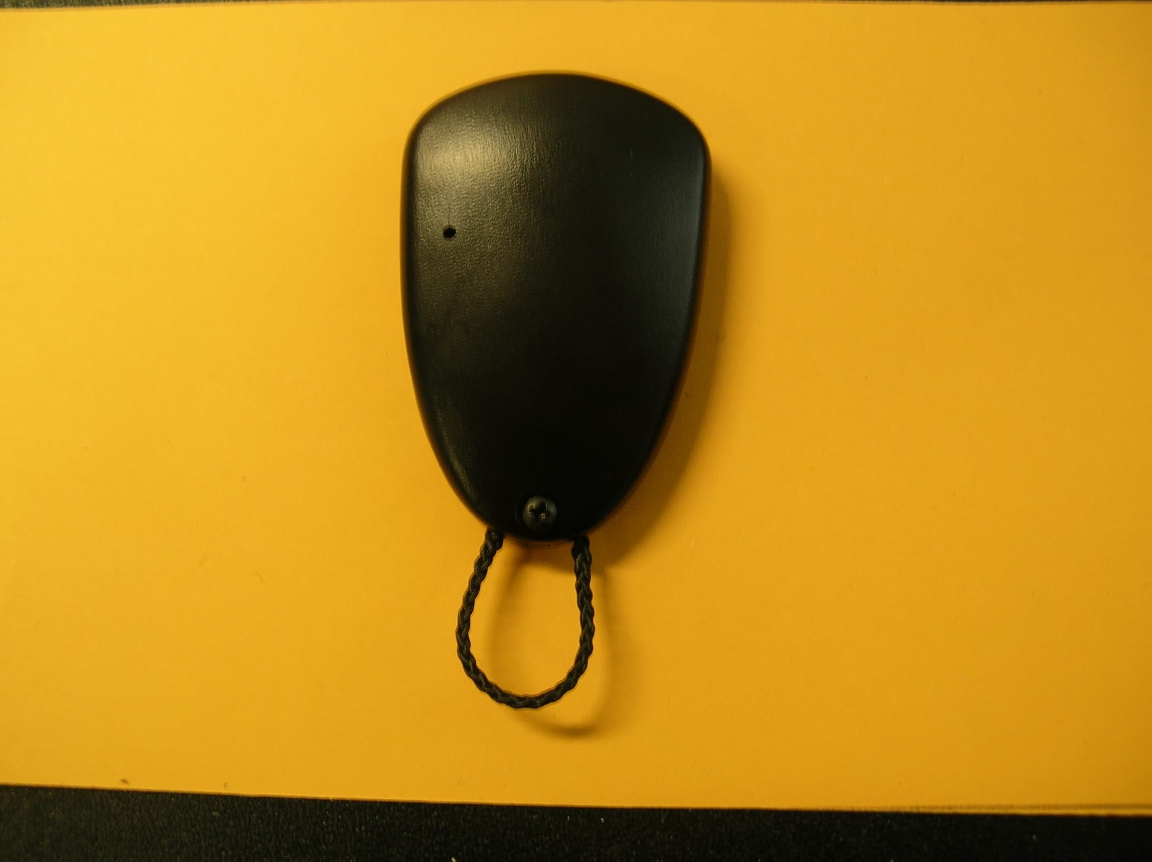
ON3TP2E
Apr 15, 2008GARAGE DOOR REMOTE CONTROL
Equipment Class
DSC - Part 15 Security/Remote Control Transmitter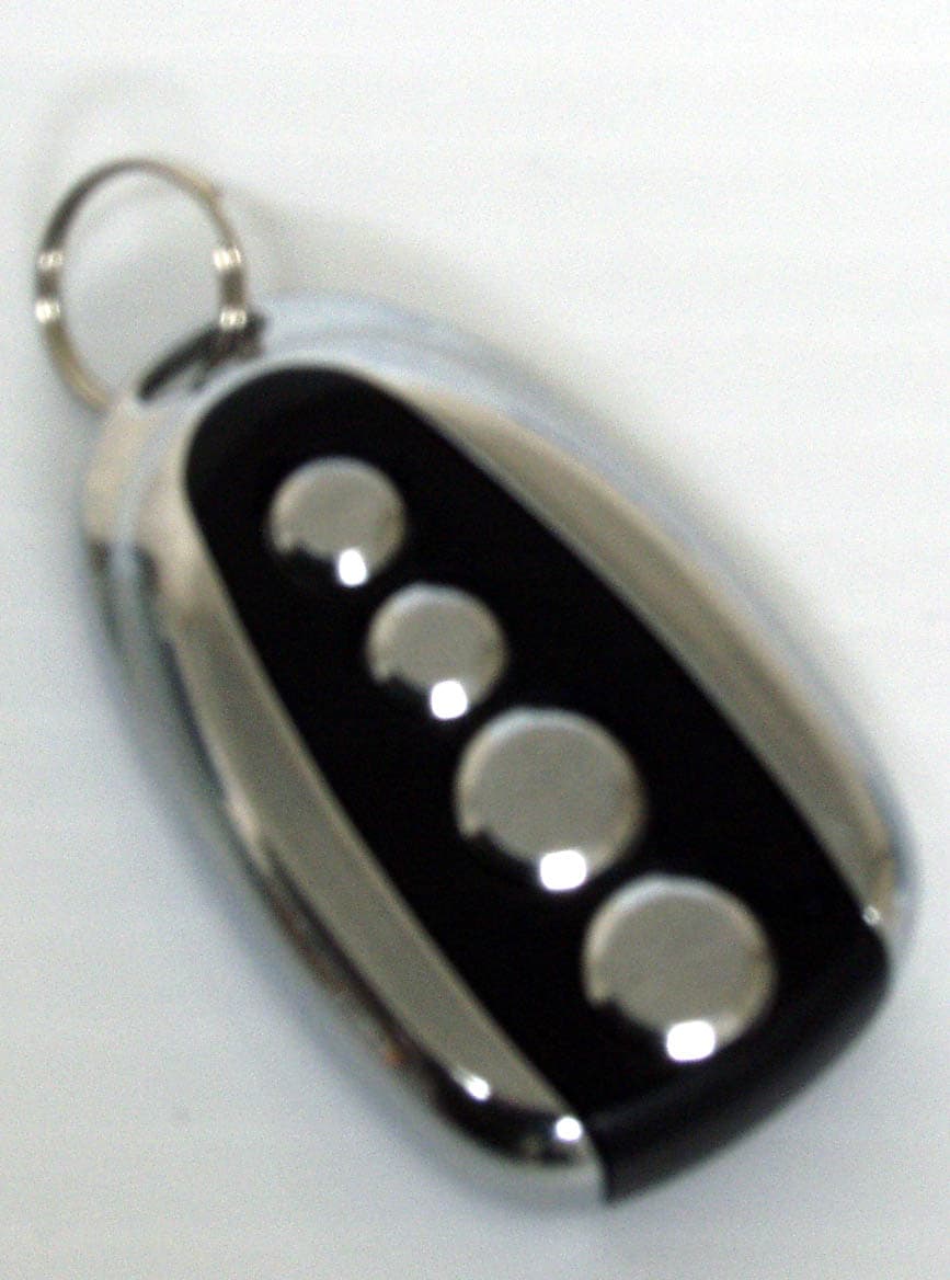
ON3TXPR02
Apr 15, 2008GARAGE DOOR REMOTE CONTROL
Equipment Class
DSC - Part 15 Security/Remote Control Transmitter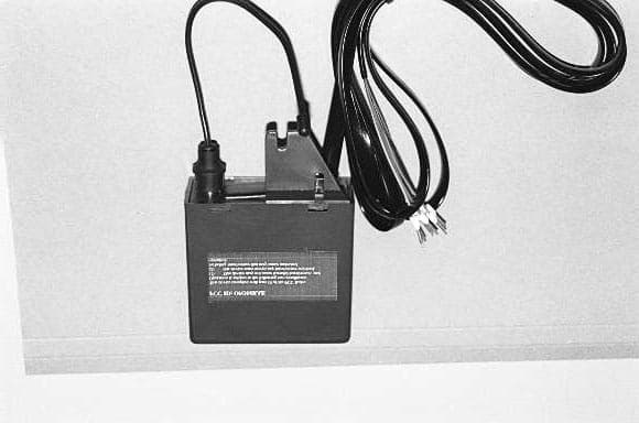
ON3MRAE
Jan 04, 2000LOW POWER RADIO RECEIVER
Equipment Class
CYY - Communications Receiver used w/Pt 15 Transmitter
ON3MRRE
Dec 22, 1999CYY - Communications Receiver used w/Pt 15 Transmitter
Equipment Class
CYY - Communications Receiver used w/Pt 15 Transmitter
ON3MPSTP2EB
Dec 21, 1999Garage Door Remote Control
Equipment Class
DSR - Part 15 Remote Control/Security Device Transceiver