OO9BS01RBluetooth Stereo Receiver
G.Tech Technology Ltd.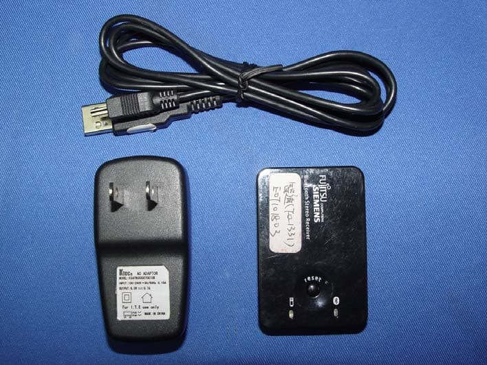
Click to zoom
Application Details
- Equipment Class
- DSS - Part 15 Spread Spectrum Transmitter
- Date of Grant
- Jan 21, 2008
- Application Purpose
- Original Equipment
- Date of Application
- Jan 15, 2008
- Equipment Note
- Bluetooth Stereo Receiver
- Frequency Range
- 2402.00000000 - 2480.00000000
- Company
- G.Tech Technology Ltd.
- Country
- China
Documents & Files
Document Text
Text extracted from the exhibit documents filed with the FCC. Open a document above to read the original.
Users Manual
Mobile phone PC Congratulation! You have got a Mobile HIFI system. Please read this manual thoroughly, and set up your Bluetooth wireless music World. 1. Check the package contents The package include: USB charging Cable Power Adapter Quick Guide Bluetooth Stereo Receiver Stereo RCA interconnect cable Power LED Connect indicator Connect Button RCA jack USB jack Bluetooth Stereo Receiver Quick Guide To pair with your phone 1. Enable Bluetooth on your phone. 2. Turn on your mobile phone. 3. Turn on the receiver by pressingresetkey. 4. In the phone's Bluetooth menu, search for devices. 5. Select Bluexon. 6. 5. Using with your mobile phone6. Using with your PC 4. How to connect 2. Charge the battery Plug the USB cable Plug the power adapter 3. To turn on the power To turn on the power, Press and hold the connect button (about 2 seconds) until the Connect indicator light blue. To turn off the power, Press and hold the connect button (about 2 seconds) until the Connect indicator light off. Blue LED power is on Blue flashing LED finish connected successfully. Red LEDBattery is charging, turns green when charged fully. Red flashing LED Battery is low 2. 1. Connect the Bluetooth receiver to your stereo system by the enclosed Stereo RCA interconnect cable. Or connect the earphone to the RCA jack of the receiver. 4. Sit back, relax and enjoy your music! Ensure your mobile or PC was built in BLUETOOTH A2DP profile before using. Remark: A2DP means Advanced Audio Distribution Profile. The device can work continuously for six hours. If it is almost no power, the power LED will flash red, please using the power adapter or the USB cable to charge. Plug one end of the USB jack into the receiver, and insert the other end to a USB port of your PC. (Make sure your PC is on) or Plug one end of the USB jack into the receiver, and the other end into the power adapter. (Make sure the power adapter connected to the power) When it is being charged, the power LED keeps lighting red. If it is fully charged, the power LED will turn green. Note: Before the first use, charge the battery fully for about 10 hours. Thereafter, recharging takes about 90 Minutes. 3. Open your favorite play list and press Play from your mobile or PC. Before using, please check if your mobile phone has Bluetooth A2DP profile, if you are not sure of that, please consult with your mobile provider. If your mobile phone doesn't support A2DP, you have to buy a Bluetooth transmitter to pair with the receiver. Enter the PIN code 0000. Select and play the Music on your mobile phone, select Use Bluetooth. Your mobile phone will be connected with the receiver and send the music. To terminate the music transportation, select Use mobile. For further details, please refer to your user manual of mobile phone. Before using, please check if your PC has Bluetooth A2DP profile, if you are not sure of that, please consult with your PC provider. If your PC has no A2DP profile, you can upgrade it by a Bluetooth Audio Dongle, after finishing upgrading Bluetooth your PC, you can pair the receiver. Connect the mobile phone or PC to your Bluetooth stereo receiver. The Blue LED on the receiver will flash when connected. (Please refer the chapter 5 and 6) Earphone Stand for receiver 7. Troubleshooting If the Bluetooth Stereo System does not work, try the following: Ensure your mobile or PC was built - in BLUETOOTH A2DP profile. Check the operation distance. Power off the receiver and reconnect again and ensure the right paring password0000. Check whether other Bluetooth device is connected. Check whether the system is out off power. Check whether the system is connected correctly. Check whether Bluetooth function of device is turned on. Operating frequency band: 2.4 to 2.48GHz unlicensed ISM band Bluetooth specification: V1.2 Output power class: class 2 Transmission power: +3dbm to -20dbm Maximum data rate Asynchronous: 723.2/57.6kbps Synchronous: 433.9/433.9Kbps Operation temperature: -40 to +85 degrees Receiving signal range: -83dbm to -20 dbm Receiving sensitivity: -83 dBm 0.1% BER Storage temperature: -40 to +105 degrees Transmit power consumption: 46mA Power supply: Standard Li-lon battery, 350mAh Rating: 3.7V 5vdc 50 100mA 8. Specifications Pairing code:0000 Only use the USB cable and net adaptor supplied. Physical Specification: Dimension: 62 mm x 42 mm x 12 mm This device complise with Part 15 of the FCC Rules. Operation is subiect to the following two conditions:(1)this device may not cause harmful interference, and (2)this device must accept any interference received,including interference that may cause undesired operation. NoteTHE MANUFACTURER IS NOT RESPONSIBLE FOR ANY RADIO OR TV INTERFERENCE CAUSED BY UNAUTHORIZED MODIFICATIONS TO THIS EQUIPMENT.SUCH MODIFICATIONS COULD VOID THE USER'S AUTHORITY TO OPERATE THE EQUIPMENT. 9. Caution: Bluedio is a trademark owned by G.Tech Technology Ltd. Other product names used in this quick guide are the properties of their respective owners and are acknowledged. 10. Copyright
Cover Letter(s)
American Telecommunications Certification Body Inc. 6731 Whittier Ave, McLean, VA 22101 January 3, 2008 RE: ATCB005788 FCC ID: OO9BS01R for G.Tech Technology Ltd. I have a few comments on this Application. Depending on your responses, kindly understand there may be additional comments. 1. The output power listed in the test report for the middle channel at 2441 MHz is calculated incorrectly. From the readings and correction factors reported, the listed output power is too low. Please correct the output power for this channel and amend the output power requested on the FCC 731 application form as necessary. 2. Please identify the FCC approved test procedure used to measure emissions from this frequency hopping spread spectrum transmitter. Although ANSI C63.4 may be used to measure spurious radiated emissions and AC line conducted emissions, this procedure does not provide details for measuring the characteristics of a frequency hopping transmitter. 3. Please confirm that the proper Declaration of Conformity (DoC) was performed for this transmitter when connected to a personal computer. The DoC authorization may not be performed by a laboratory located in China because there is no Mutual Recognition Agreement (MRA) in operation between China and the United States. Richard Fabina Examining Engineer mailto: [email protected] The items indicated above must be submitted before processing can continue on the above referenced application. Failure to provide the requested information may result in application termination. Correspondence should be considered part of the permanent submission and may be viewed from the Internet after a Grant of Equipment Authorization is issued. Please do not respond to this correspondence using the email reply button. In order for your response to be processed expeditiously, you must submit your documents through the AmericanTCB.com website. Also, please note that partial responses increase processing time and should not be submitted. Any questions about the content of this correspondence should be directed to the sender.
Cover Letter(s)
Multiple files are bound together in this PDF Package. Adobe recommends using Adobe Reader or Adobe Acrobat version 8 or later to work with documents contained within a PDF Package. By updating to the latest version, you’ll enjoy the following benefits: • Efficient, integrated PDF viewing • Easy printing • Quick searches Don’t have the latest version of Adobe Reader? Click here to download the latest version of Adobe Reader If you already have Adobe Reader 8, click a file in this PDF Package to view it.
External Photos
Page 6 G. tech Technology Ltd. Bluetooth Stereo Receiver FCC ID:OO9BS01R Photographs Figure 1 General Appearance Figure 2 General Appearance Page 7 G. tech Technology Ltd. Bluetooth Stereo Receiver FCC ID:OO9BS01R Figure 3 General Appearance Figure 4 General Appearance Label Location
ID Label/Location Info
Page 7 G. tech Technology Ltd. Bluetooth Stereo Receiver FCC ID:OO9BS01R Figure 3 General Appearance Figure 4 General Appearance Label Location
ID Label/Location Info
FCC ID: OO9BS01R 40.0 mm 20.0 mm Model: BS01R
Internal Photos
Page 8 G. tech Technology Ltd. Bluetooth Stereo Receiver FCC ID:OO9BS01R Figure 5 Inside of the EUT Figure 6 Inside of the EUT Page 9 G. tech Technology Ltd. Bluetooth Stereo Receiver FCC ID:OO9BS01R Figure 7 Component Side of the PCB Figure 8 Component Side of the PCB Page 10 G. tech Technology Ltd. Bluetooth Stereo Receiver FCC ID:OO9BS01R Figure 9 Component Side of the PCB Figure 10 Adaptor of the EUT Page 11 G. tech Technology Ltd. Bluetooth Stereo Receiver FCC ID:OO9BS01R Figure 11 Adaptor of the EUT Figure 12 USB Cable
Test Report
FCC ID:OO9BS01R Audix Technology (Shenzhen) Co., Ltd. Report No. ACS-F07549 APPLICATION FOR CERTIFICATION On Behalf of G. tech Technology Ltd. Bluetooth Stereo Receiver Model Number: BS01R Prepared for : G. tech Technology Ltd. No.21, Jinding Industrial Park, West Jinfeng Road, Tangjiawan Town, Xiangzhou District Zhuhai Guangdong China Prepared By : Audix Technology (Shenzhen) Co., Ltd. No. 6, Ke Feng Rd., 52 Block, Shenzhen Science & Industrial Park, Nantou, Shenzhen, Guangdong, China Tel: (0755) 26639496 Report Number : ACS-F07549 Date of Test : Dec.17~21, 2007 Date of Report : Dec.28, 2007 FCC ID:OO9BS01R Audix Technology (Shenzhen) Co., Ltd. Report No. ACS-F07549 TABLE OF CONTENTS Description Page FCC Test Report for Declaration of Conformity 1. SUMMARY OF STANDARDS AND RESULTS................................................................... 1-1 1.1. Description of Standards and Results ............................................................................................1-1 2. GENERAL INFORMATION .................................................................................................. 2-1 2.1. Description of Device (EUT) .........................................................................................................2-1 2.2. Tested Supporting System Details .................................................................................................2-2 2.3. Test Facility ...................................................................................................................................2-3 2.4. Measurement Uncertainty ..............................................................................................................2-3 3. POWER LINE CONDUCTED EMISSION TEST ................................................................ 3-1 3.1. Test Equipments.............................................................................................................................3-1 3.2. Block Diagram of Test Setup .........................................................................................................3-1 3.3. Power Line Conducted Emission Test Limits................................................................................3-1 3.4. Configuration of EUT on Test .......................................................................................................3-2 3.5. Operating Condition of EUT..........................................................................................................3-2 3.6. Test Procedure................................................................................................................................3-2 3.7. Power Line Conducted Emission Test Results ..............................................................................3-2 4. RADIATED EMISSION TEST ............................................................................................... 4-5 4.1. Test Equipment ..............................................................................................................................4-5 4.2. Block Diagram of Test Setup .........................................................................................................4-5 4.3. Radiated Emission Limit................................................................................................................4-6 4.4. EUT Configuration on Test............................................................................................................4-6 4.5. Operating Condition of EUT..........................................................................................................4-7 4.6. Test Procedure................................................................................................................................4-7 4.7. Radiated Emission Test Results .....................................................................................................4-7 5. CARRIER FREQUENCY SEPARATION TEST ................................................................. 5-1 5.1. Test Equipment ..............................................................................................................................5-1 5.2. Test Information .............................................................................................................................5-1 5.3. Test Results ....................................................................................................................................5-1 6. 20 DB BANDWIDTH TEST .................................................................................................... 6-1 6.1. Test Equipment ..............................................................................................................................6-1 6.2. Test Information .............................................................................................................................6-1 6.3. Test Results ....................................................................................................................................6-1 7. NUMBER OF HOPPING FREQUENCY TEST ................................................................... 7-1 7.1. Test Equipment ..............................................................................................................................7-1 7.2. Test Information .............................................................................................................................7-1 7.3. Test Results ....................................................................................................................................7-1 8. DWELL TIME TEST ............................................................................................................... 8-1 8.1. Test Equipment ..............................................................................................................................8-1 8.2. Test Information ..................................................…
Text truncated - open the document above for the full version.
Test Setup Photos
FCC ID:OO9BS01R Page 12-1 Audix Technology (Shenzhen) Co., Ltd. Report No. ACS-F07549 12. PHOTOGRAPH 12.1.Photos of Power Line Conducted Emission Test FCC ID:OO9BS01R Page 12-2 Audix Technology (Shenzhen) Co., Ltd. Report No. ACS-F07549 12.2.Photos of Radiated Emission Test 30-1000MHz FCC ID:OO9BS01R Page 12-3 Audix Technology (Shenzhen) Co., Ltd. Report No. ACS-F07549 Above 1000MHz
Contact Information
Applicant
Sulia Li(Certified Associate)
Technical Contact
Audix Technology (Shenzhen) Co., Ltd.Ken Lu
[email protected]+86-755-266-39497
52 Block Shenzhen Science & Industry · Shenzhen · China
Non-Technical Contact
Audix Technology (Shenzhen) Co., Ltd.Kris Zheng
[email protected]+86-755-266-39497
Test Firm
Audix Technology (Shenzhen) Co., Ltd.Smart Tsai
Technical Specifications
| # | Rule Parts | Frequency Range | Power Output |
|---|---|---|---|
| 1 | 15C | 2.40 GHz - 2.48 GHz | 895.00 µW |
Other Applications from G.Tech Technology Ltd.
OO9P729
Aug 06, 2026WIRELESS GAMING MOUSE
Equipment Class
DTS - Digital Transmission System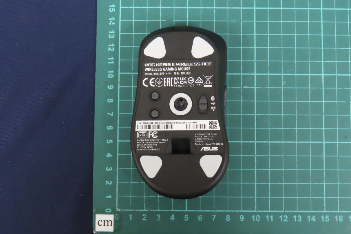
OO9P714
May 09, 2024GAMING MOUSE
Equipment Class
DTS - Digital Transmission System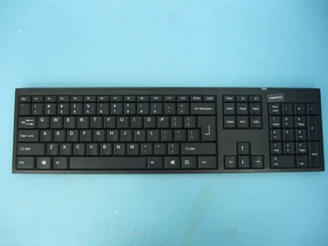
OO9GK381
Jun 17, 20152.4GHz Wirteless Keyboard
Equipment Class
DXX - Part 15 Low Power Communication Device Transmitter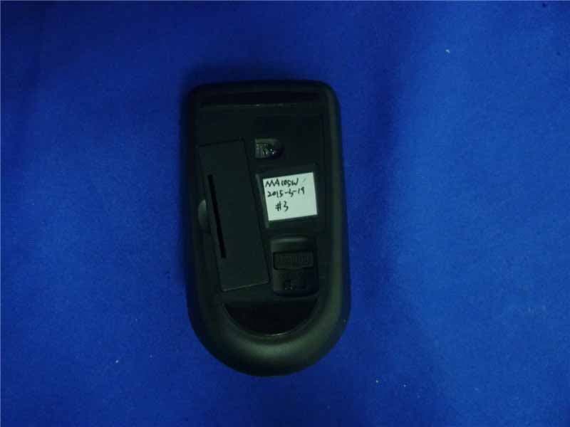
OO9MA105W
May 06, 20152.4GHz Wireless Mouse
Equipment Class
DXX - Part 15 Low Power Communication Device Transmitter
OO9KB313W
May 06, 20152.4GHz Wireless Keyboard
Equipment Class
DXX - Part 15 Low Power Communication Device Transmitter