OO9K1801SWireless Keyboard
G.Tech Technology Ltd.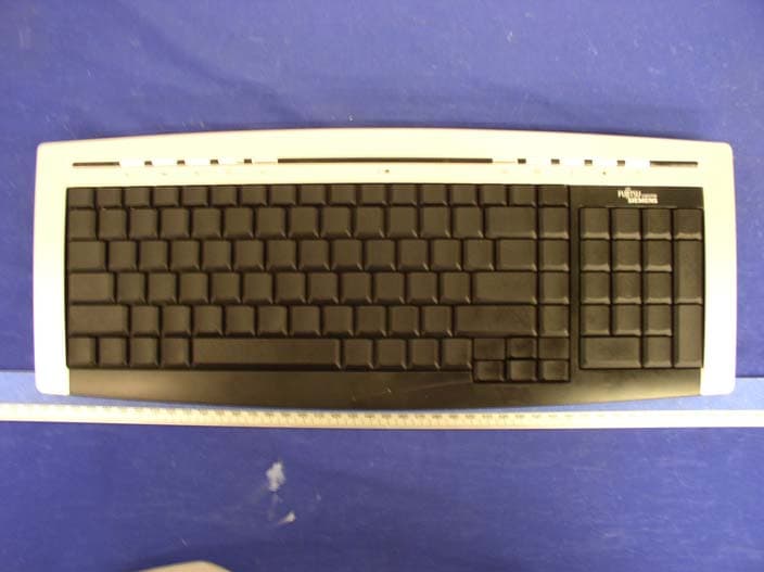
Click to zoom
Application Details
- Equipment Class
- DXX - Part 15 Low Power Communication Device Transmitter
- Date of Grant
- Oct 27, 2004
- Application Purpose
- Original Equipment
- Date of Application
- Oct 27, 2004
- Equipment Note
- Wireless Keyboard
- Frequency Range
- 27.04500000 - 27.04500000
- Company
- G.Tech Technology Ltd.
- Country
- China
Documents & Files
Document Text
Text extracted from the exhibit documents filed with the FCC. Open a document above to read the original.
Users Manual
PDF created with FinePrint pdfFactory trial version http://www.fineprint.com Wireless Keyboard Slim English - 1 - Wireless radio keyboard and radio mouse The wireless keyboard and optical mouse operate with digital radio technology. There is no connecting cable to hinder communication between the keyboard, the mouse and your computer. The keyboard and mouse need not be in the line of sight to the receiver. The keyboard and mouse use radio frequencies to send data to the receiver, which forwards these to your computer. You can use the keyboard and mouse on any computer equipped with a free USB interface. CE marking This equipment complies with the requirements of Directive 1999/5/EC of the European Parliament and Commission from 9 March 1999 governing Radio and Telecommunications Equipment and mutual recognition of conformity. This device is approved for use in Belgium, Denmark, Germany, Finland, France, Greece, Great Britain, Ireland, Iceland, Italy, Luxembourg, the Netherlands, Norway, Austria, Portugal, Sweden and Spain. Installing the batteries i Under all circumstan ces only use batteries and rechargeable batteries of the same type. The cordless optical mouse uses 2×AAA rechargeable batteries. 1. Remove the battery compartment cover on the bottom of the mouse. 2. Insert 2×AAA rechargeable batteries in the battery compartment. A diagram in the battery compartment shows correct installation. 3. Carefully place the cover back into place. The cordless keyboard uses 2×AAA batteries. PDF created with FinePrint pdfFactory trial version http://www.fineprint.com Wireless Keyboard Slim English - 2 - 1. Remove the battery compartment cover on the bottom of the cordless keyboard. 2. Insert 2× AAA batteries. A diagram in the battery compartment shows the correct installation. 3. Carefully place the cover back into place. Connecting the receiver 1. Connect the receiver's cable to the USB port of your computer and follow the instructions displayed on screen. 2. Set up the receiver at least 20 cm away from other electronic devices, such as the computer monitor or external storage drives to achieve optimum performance. i Maintain a distance – even in office environments – with the keyboard, mouse and receiver of at least 5 meter from other radio device to prevent interference during transmission of the signals. Setting up the ID wireless link – Keyboard and Mouse ID wireless link will be set up separately SLIM KEYBOARD 1. Press the connection button “CONNECT” on the receiver after booting the system. Indicator RX lights. 2. To set up the keyboard wireless link, press the RESET button on the bottom of the slim keyboard. Indicator RX light will be off. OPTICAL MOUSE 1. Press the connection button “CONNECT” on the receiver after booting the system. Indicator RX lights. 2. To set up the mouse wireless link, press the RESET button on the bottom of the mouse. Indicator RX light will be off. i The setup must be completed within 30 seconds. If setup time exceeds 30 seconds, repeat procedure. Change communication code CHRG CONNECT RX PDF created with FinePrint pdfFactory trial version http://www.fineprint.com Wireless Keyboard Slim English - 3 - The desktop has communication code to the computer to avoid the interference with other desktop. You have to change the code if there is any interference. The interference only exists when many sets of mouse & keyboard used at the same time. Keyboard and Mouse ID wireless link will be changed separately. i l For the primary setup, both two wireless linkages, one for receiver and mouse, another for receive and keyboard, should be completed. l The communication ID for mouse and keyboard can be changed separately. l The setup must be completed within 30 seconds. If setup time exceeds 30 seconds, repeat procedure. SLIM KEYBOARD 1. Press the connection button “CONNECT” on the receiver, Indicator RX lights. 2. Press the “RESET” button on the bottom of the slim keyboard. Indicator RX light will be off as soon as the linkage is completed. OPTICAL MOUSE 1. Press the connection button “CONNECT” on the receiver, Indicator RX lights. 2. Press the “RESET” button on the bottom of the mouse. Indicator RX light will be off as soon as the linkage is completed. Charging the rechargeable batteries- Quickly Charging Before using the mouse for the first time, place it in the charging unit of the receiver for approximately 2 hours to charge the rechargeable batteries. i Caution: For recharging do not use dis- rechargeable batteries, only use rechargeable batteries. 1. Make sure the adaptor is connected with the power. 2. Put the mouse into the charging-stand (see pictures). 3. The “CHAG” light color is red when battery is being recharged, and it will turn into green when the PDF created with FinePrint pdfFactory trial version http://www.fineprint.com Wireless Keyboard Slim English - 4 - battery is fully recharged. 4. The recharge power is available during the power off state of the computer, only if the input electricity is available. Installing the software To take advantage of all the features of your mouse and keyboard, please install the software that comes with the product. The software provided offers you several advantages: − Activation of the multimedia keys of your keyboard and operating display on the screen when the multimedia keys are pressed. − Various functions for the mouse. − Icons in the taskbar. 1. Turn on your computer and start Windows. 2. Insert the CD in the corresponding drive. The CD starts automatically. If this is not the case, start the “Setup” program from the CD. 3. Follow the on-screen instructions. Displaying keyboard modes In the Windows taskbar icons indicate which keyboard mode is active. They match the displays on ordinary keyboards. The symbol is green when the respective mode is activated and light grey when it is deactivated. A Uppercase mode (CapsLock) 1 Virtual numeric keypad (NumLock) Stop screen output (ScrollLock) Using your mouse The mouse has th…
Text truncated - open the document above for the full version.
Block Diagram
1234 A B C D 4321 D C B A Key Input Data output VCC Data out Oscillator1 Power Amplification ANT Power control Key output K e y M a t r i x Reset Power control MCU LED Power control VCC BATTERY DC-DC Low Voltage Detector Reset TX=27.045MHz K1801S Block Diagram MemoryMemory Crystal 27.045MHz PDF created with FinePrint pdfFactory trial version http://www.fineprint.com
External Photos
EXHIBIT C - EUT EXTERNAL PHOTOGRAPHS Chassis - Top View Chassis - Bottom View
ID Label/Location Info
EXHIBIT A - FCC PRODUCT LABELING AND WARNING STATEMENT Proposed Label Location on EUT Chassis Rear of EUT/FCC ID Label Proposed Location
Internal Photos
EXHIBIT C - EUT INTERNAL PHOTOGRAPHS Chassis – Cover Off View EUT – Component View EUT – Solder View
Operational Description
Description of the Wireless Keyboard K1801S Circuit +3.3V direct current voltage has been provided by IC-U5 and others electronic materials on the keyboard. MCU-U3 will be identified which key did you press. The principle is that 32 and 33 feet of MCU-U3 output TXD and TXP signal to Transmit and Surge Circuit from Modulate Tube of Q6 (9014) and Surge Tube Q5 (2223Y). The Q1 (9014) is Reset circuit, and U1 is IC for inspection low voltage. When the IC inspected batteries as low voltage on 2.1V or less that the D4 indicator LED will light. PDF created with FinePrint pdfFactory trial version http://www.fineprint.com
Schematics
123456 A B C D 654321 D C B A R3 22K VCC /Reset R32 10K CHECK PE3(LED) 19 PE2(LED) 18 PB1 9 VSS 17 PD4 16 NC 12 PD7 13 PD6 14 PD75 15 PB5 1 PB4 2 PA3 3 PA2 4 PA1 5 PA0 6 PB3 7 PB2 8 NC 11 PB0 10 PC0 20 PC1 21 PC2 22 PE0 23 PE1 24 PC3 25 PC4 26 PC5 27 PC6 28 PC7 29 PD0 30 PD1 31 PD2 32 PD3 33 PE4(LED) 34 RESET 35 VDD 36 OSC1 37 OSC2 38 NC 39 NC 40 NC 41 NC 42 PA7 43 PA6 44 PA5 45 PA4 46 PB7 47 PB6 48 U3 HT82K68E R1 R2 R3 R4 R5 R6 R7 R8 R9 R10 R12 R11 R13 R14 R17 R18R16 R15 C1 C2 C3 C4 C5 C6 C7 C8 TXP TXD /Reset C56 0.1uF C55 22uF CHECK R1 R2 R3 R4 R5 R6 R7 R8 R9 R10 R11 R12 R13 R14 R15 R16 R17 R18 C1 C2 C3 C4 C5 C6 C7 C8 X17 1 X16 2 X15 3 X14 4 X13 5 X12 6 X11 7 X10 8 X9 9 X8 10 X7 11 X6 12 X5 13 X4 14 X3 15 X2 16 X1 17 X0 18 Y7 20 Y6 21 Y0 19 Y1 22 Y2 23 Y3 24 Y4 25 Y5 26 P1 FG-WALL TXP TXD VCC VCC R1 22K VCC C1 0.01uF 1 2 3 Q2 MMBT3906 R20 220R D4 3R2SD R15 22K C23 100pF C25 100pF R25 1.5K 1 2 3 Q5 KSC2223Y C4 * C5 * R2 22KR17 * R26 47R C8 0.1uF R18 47K C27 1000pF 1 2 L4 * C24 * 1 ANT1=300mm 1 2 3 Q6 9014 C26 27pF C29 15pF C28 1000pF VCC X1 27.045M C30 22uF 1 2 3 Q7 KSC2223Y R27 100K R28 20R 1 2 L 6 S M D - 2 . 2 u H C31 30pF C32 30pF C33 220pF TXP1 VCC C9 0.1uF 1 2 L7 6.8uH 12 L8 * R29 0R TXP TXD C35 0.1uF R19 * TXP1 T4 T7 T8 1 J3 BAT+ 1 J4 BAT- 12 L5 0406-220uH C6 100uF/16V C19 CD288H-47uF/25V D7 1N5819 VCC R39 220K 12 L1 0307-10uH 12 L2 0307-10uH BAT+ T1 T2 VCC C8 C7 C6 C5 C4 C3 C2 C1 C17 33pF C15 33pF C1633pF C1033pF C11 33pF C12 33pF C1333pF C14 33pF C20 30pF C21 30pF XTAL2 XTAL1 XTAL1 XTAL2 XTAL1 XTAL2 1 2 3 Q1 9014 R4 22K R5 22K D1 1N4148 SW1 TS-04P C1 T3 C3 103pF C38 100pF Vout 2 Vin 3 G N D 1 U5 RT9261-33CX C2 1uF VDD 3 G N D 2 VOUT 1 U4 * BAT+ C7 0.1uF X3 2M T5 T6 1 2 ANT2 * C18 * A0 1 A1 2 A2 3 VSS 4 SDA 5 SCL 6 WP 7 VCC 8 U2 KS24C010 SCL SDA VCC C22 0.1uF SDA SCL T9 T10 T11 T12 T13 T14 T15 T16 T17 T18 T19 GND 3 VCC 2 OUT 1 U1 RT9808-21CX K1801S-SCH PDF created with FinePrint pdfFactory trial version http://www.fineprint.com
Test Report
Note: The test report is specially limited to the above company and the product model only. It may not be duplicated without prior written consent of Bay Area Compliance Laboratory Corporation. This report must not be used by the client to claim product certification, approval, or endorsement by NVLAP, NIST or any agency of the US Government. FCC PART 15.227 EMI MEASUREMENT AND TEST REPORT For G.tech Technology Ltd. NO.21, JINDING INDUSTRIAL PARK, WEST JINFENG ROAD, TANGJIAWAN TOWN, XIANGZHOU DISTRICT ZHUHAI GUANGDON CHINA FCC ID: OO9K1801S This Report Concerns: Original Report Equipment Type: Wireless Multimedia Keyboard, Transmitter Test Engineer: Jerry Wang Report No.: R0409079 Report Date: 2004-10-07 Reviewed By: Hang Tan Prepared By: Bay Area Compliance Laboratory Corporation 230 Commercial Street Sunnyvale, CA 94085 Tel: (408) 732-9162 Fax: (408) 732-9164 G.tech Technology Ltd. FCC ID: OO9K1801S Report # R0409079Rpt.doc Page 2 of 10 FCC 15.227 Report TABLE OF CONTENTS GENERAL INFORMATION.......................................................................................................................................3 PRODUCT DESCRIPTION FOR EQUIPMENT UNDER TEST (EUT) ....................................................................................3 OBJECTIVE...................................................................................................................................................................3 RELATED SUBMITTAL(S)/GRANT(S).............................................................................................................................3 TEST METHODOLOGY..................................................................................................................................................3 TEST FACILITY.............................................................................................................................................................3 SYSTEM TEST CONFIGURATION ..........................................................................................................................4 JUSTIFICATION.............................................................................................................................................................4 SCHEMATICS AND BLOCK DIAGRAM............................................................................................................................4 EQUIPMENT MODIFICATIONS.......................................................................................................................................4 TEST SETUP CONFIGURATION......................................................................................................................................4 SUMMARY OF TEST RESULTS ...............................................................................................................................5 §15.203 - ANTENNA REQUIREMENT......................................................................................................................6 STANDARD APPLICABLE..............................................................................................................................................6 §15.205, §15.209, §15.227(B) - RADIATED EMISSIONS TEST ..............................................................................7 MEASUREMENT UNCERTAINTY....................................................................................................................................7 EUT SETUP..................................................................................................................................................................7 TEST EQUIPMENT LIST AND DETAILS...........................................................................................................................7 TEST PROCEDURE........................................................................................................................................................8 CORRECTED AMPLITUDE & MARGIN CALCULATION...................................................................................................9 SUMMARY OF TEST RESULTS.......................................................................................................................................9 RADIATED EMISSIONS TEST RESULT DATA.................................................................................................................9 §15.227(B) - OUT OF BAND EMISSION .................................................................................................................10 TEST EQUIPMENT LIST AND DETAILS.........................................................................................................................10 TEST RESULT.............................................................................................................................................................10 G.tech Technology Ltd. FCC ID: OO9K1801S Report # R0409079Rpt.doc Page 3 of 10 FCC 15.227 Report GENERAL INFORMATION Product Description for Equipment Under Test (EUT) The G.tech Technology Ltd. ’s product, FCC ID: OO9K1801S or the "EUT" as referred to in this report is a transmitter of a W i r e less Multimedia Keyboard. The EUT measures approximately 41.5cm L x 16.3cmW x 2.5cm H. The EUT operates at the frequency of 27.045MHz. * The test data gathered are from production sample, serial number: PK0027605 provided by the manufacturer. Objective This Type approval report is prepared on behalf of G.tech Technology Ltd. in accordance with Part 2, Subpart J, and Part 15, Subparts A, B and C of the Federal Communication Commissions rules. The objective to determine compliance with FCC rules, sec 15.203, 15.205, 15.209 and sec 15.227. Related Submittal(s)/Grant(s) No Related Submittals. Test Methodology All measurements contained in this report were conducted with ANSI C63.4-2001, American National Standard for Methods of Measurement of Radio-Noise Emissions from L…
Text truncated - open the document above for the full version.
Test Setup Photos
EXHIBIT B - TEST SETUP PHOTOGRAPHS Transmitter Radiated Emission
Contact Information
Applicant
Sulia Li(Certified Associate)
Test Firm
Bay Area Compliance LaboratoryJohn Chan
Technical Specifications
| # | Rule Parts | Frequency Range | Power Output |
|---|---|---|---|
| 1 | 15C | 27.045 MHz - 27.045 MHz | - |
Other Applications from G.Tech Technology Ltd.
OO9P729
Aug 06, 2026WIRELESS GAMING MOUSE
Equipment Class
DTS - Digital Transmission System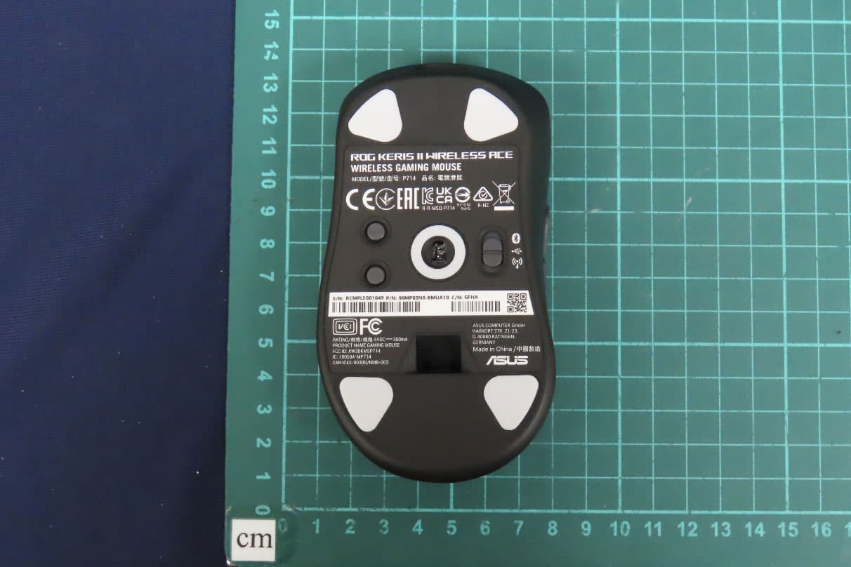
OO9P714
May 09, 2024GAMING MOUSE
Equipment Class
DTS - Digital Transmission System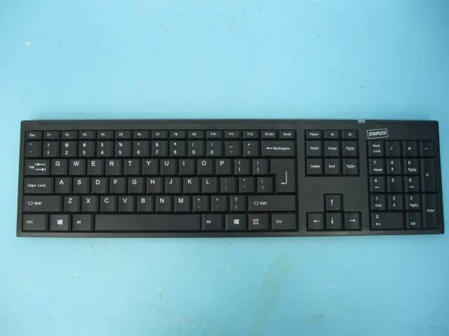
OO9GK381
Jun 17, 20152.4GHz Wirteless Keyboard
Equipment Class
DXX - Part 15 Low Power Communication Device Transmitter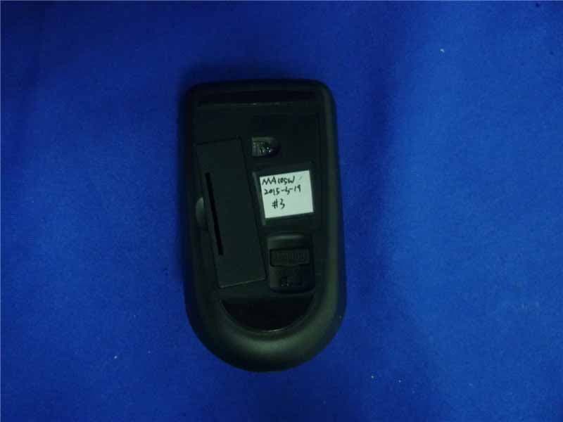
OO9MA105W
May 06, 20152.4GHz Wireless Mouse
Equipment Class
DXX - Part 15 Low Power Communication Device Transmitter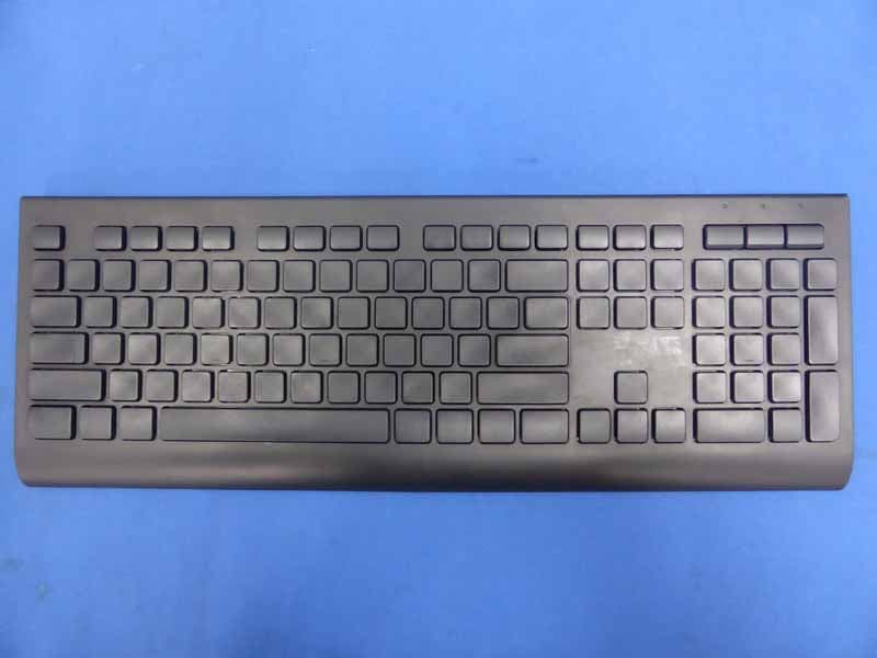
OO9KB313W
May 06, 20152.4GHz Wireless Keyboard
Equipment Class
DXX - Part 15 Low Power Communication Device Transmitter