OO9K8732Wireless Keyboard
G.Tech Technology Ltd.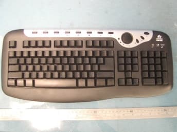
Click to zoom
Application Details
- Equipment Class
- DXX - Part 15 Low Power Communication Device Transmitter
- Date of Grant
- Jul 20, 2004
- Application Purpose
- Original Equipment
- Date of Application
- Jul 20, 2004
- Equipment Note
- Wireless Keyboard
- Frequency Range
- 26.96000000 - 27.28000000
- Company
- G.Tech Technology Ltd.
- Country
- China
Documents & Files
Document Text
Text extracted from the exhibit documents filed with the FCC. Open a document above to read the original.
Users Manual
Please read this user’s guide before installing, setting up and using your new product www.radioshack.com Thank you for purchasing your Compaq27 MHz RF Wireless Keyboard and Optical Mouse from RadioShack. This combo is specially designed for offi ces with up to 4096 ID codes for the keyboard and 2048 ID codes for the mouse, so you can use multiple sets in the same offi ce at the same time. With a single USB connection you can connect both the keyboard and the mouse to your computer. 26-762 27 MHz RF Wireless Keyboard & Optical Mouse Combo this user’s guide wireless keyboard wireless mouse charger / receiver AC adapter CD (drivers) 2 AA batteries (non-recharageable alkaline)2 AAA batteries (rechargeable NI-MH) Installing the Batteries You can power the mouse with two AAA batteries, and the keyboard with two AA batteries. 1 Remove the compartment cover from both the keyboard and mouse. 2 Insert the AA batteries into the keyboard and the AAA batteries into the mouse. Be sure to match the polarity markings. 3 Replace the compartment covers. Recharging the Batteries Connect one end of the supplied adapter to the charger/receiver’s DC port and the other end to a standard AC outlet. Place the mouse in the charging stand. The red LED lights when the batteries are charging. The green LED lights when charging is complete.When the batteries in the mouse get low, the red LED on the mouse fl ashes. When the batteries in the keyboard get low, the battery indicator turns red. DC port CONNECT Installing the Windows 98 Driver Your mouse and keyboard work with Microsoft Windows 98/2000/Me/XP/NT. Except for Windows 98, they should work well without installing the driver. If you are using Windows 98, be sure to install the driver before connecting the keyboard and mouse. 1 Exit all open Windows applications. 2 Insert the supplied CD in your computer’s CD-ROM driver. Installation instructions will be displayed on the computer automatically. 3 Follow the on-screen instructions. Setting the Channel The keyboard and mouse offer 2 channels, CH1 and CH2. The receiver automatically detects the mouse’s channel. You will need to change the channel of the keyboard so the keyboard and mouse are on different channels. If interference is caused by the other computers, reset the channel. To reset the channel on the keyboard, slide CH1 / CH2 on the back of the keyboard. To reset the channel on the mouse, remove the battery compartment on the mouse, and use a pointed object to slide the switch inside the compartment to CH1 or CH2. Then replace the cover. 1 Connect the charger / receiver’s USB cable to your computer’s USB port. 2 Press CONNECT on the receiver. The receiver’s indicator lights green. 3 Press the reset key at back of the mouse and CONNECT on the keyboard. When you change the channel or replace the batteries, you will need to repeat steps 2 and 3. Reset button CH1 / CH2 Changing the ID Code To avoid interference with other Windows desktop sets, you will need to change the ID code. 1 Use a pointed object to press the reset button on the back of the mouse and press CONNECT on the right top of keyboard to change the code. 2 Press CONNECT on the receiver. 3 Press the reset key on the back of the mouse. CH1 / CH2 CONNECT ©2004 RadioShack Corporation.All rights reserved. RadioShack and RadioShack.com are trademarks used by RadioShack Corporation. 26-762 04A04 printed in China Keep the mouse and keyboard combo dry. If they get wet, wipe them dry immediately. Use and store the combo only in room temperature environments. Handle the combo carefully. Do not drop it. Keep the combo away from dust and dirt, and wipe it with a damp cloth occasionally to keep it looking new. This equipment has been tested and found to comply with the limits for a Class B digital device, pursuant to Part 15 of the FCC Rules. These limits are designed to provide reasonable protection against harmful interference in a residential installation. This equipment generates, uses, and can radiate radio frequency energy and, if not installed and used in accordance with the instructions, may cause harmful interference to radio communications. However, there is no guarantee that interference will not occur in a particular installation. If this equipment does cause harmful interference to radio or television reception, which can be determined by turning the equipment off and on, the user is encouraged to try to correct the interference by one or more of the following measures: • Reorient or relocate the receiving antenna. • Increase the separation between the equipment and receiver. • Connect the equipment into an outlet on a circuit different from that to which the receiver is connected. Consult your local RadioShack store or an experienced radio/TV technician for help.If you cannot eliminate the interference, the FCC requires that you stop using your phone. Changes or modifi cations not expressly approved by RadioShack may cause interference and void the user’s authority to operate the equipment. This product is warranted by RadioShack against manufacturing defects in material and workmanship under normal use for ninety (90) days from the date of purchase from RadioShack company-owned stores and authorized RadioShack franchisees and dealers. EXCEPT AS PROVIDED HEREIN, RadioShack MAKES NO EXPRESS WARRANTIES AND ANY IMPLIED WARRANTIES, INCLUDING THOSE OF MERCHANT-ABILITY AND FITNESS FOR A PARTICULAR PURPOSE, ARE LIMITED IN DURATION TO THE DURATION OF THE WRITTEN LIMITED WARRAN-TIES CONTAINED HEREIN. EXCEPT AS PROVIDED HEREIN, RadioShack SHALL HAVE NO LIABILITY OR RESPONSIBILITY TO CUSTOMER OR ANY OTHER PERSON OR ENTITY WITH RESPECT TO ANY LIABILITY, LOSS OR DAMAGE CAUSED DIRECTLY OR INDIRECTLY BY USE OR PERFORMANCE OF THE PRODUCT OR ARISING OUT OF ANY BREACH OF THIS WARRANTY, INCLUDING, BUT NOT LIMITED TO, ANY DAM-AGES RESULTING FROM INCONVENIENCE, LOSS OF TIME, DATA, PROPERTY, REVENUE, OR PROFIT OR ANY INDIRECT, SPECIAL, INCI-DENTAL, OR CONSEQUENTIAL DA…
Text truncated - open the document above for the full version.
Block Diagram
1234 A B C D 4321 D C B A Date: Filename: E:\G-TECH 2004\K8732\DOCUMENT\K8732-Block.sch Drawn TITLE:K8732 Block Diagram Approved Confirmed by: by: by: Version 文 件 编 号 GT-R0101-A Key Input Data output VCC Data out Oscillator1 Power Amplification ANT Power control Key output K e y M a t r i x Reset Power control MCU LED3 TXD VCC BATTERY DC-DC Low Voltage Detector Reset VCC CH2 Scan control Scan control Scroll InputVOL- VOL+ LED2 CH1 TX CH1=27.045MHz CH2=27.195MHz O S C 1 O S C 2 LED1/ID_KEY LED2/SDA 2 13 SW ch_check PDF created with FinePrint pdfFactory trial version http://www.fineprint.com
External Photos
Wireless keyboard K8732 external photo
Internal Photos
Wireless keyboard K8732 internal photo
Operational Description
Page 1 of 1 Product Operation Description This product K8732 is wireless keyboard, which are 104/105 standard keys, 6 multimedia keys and use two AAA batteries. The main function of K8732 is modulating pressing keys message, transmit RF signal to associated receiver. The operation frequency range is 26.96 to 27.28MHz, K8732 has two channels, and the frequency channel can be selected via change a switch on the bottom, then press CONNECT key on the bottom of the keyboard, also you need to press CONNECT key on the receiver at the same time, the connection will be set up within one minute. The keyboard K8732 has a battery-low indicator, when you press any key and the power indicator become red, that means the batteries are out of power.
Schematics
123456 A B C D 654321 D C B A Date:Filename:E:\G-TECH 2004\K8732\V11\K8732V11.sch Drawn TITLE: K8732-SCH Approved Confirmed by: by: by: Version V11 文 件 编 号 GT-R0101-A PE3(LED) 19 PE2(LED) 18 PB1 9 VSS 17 PD4 16 NC 12 PD7 13 PD6 14 PD75 15 PB5 1 PB4 2 PA3 3 PA2 4 PA1 5 PA0 6 PB3 7 PB2 8 NC 11 PB0 10 PC0 20 PC1 21 PC2 22 PE0 23 PE1 24 PC3 25 PC4 26 PC5 27 PC6 28 PC7 29 PD0 30 PD1 31 PD2 32 PD3 33 PE4(LED) 34 RESET 35 VDD 36 OSC1 37 OSC2 38 NC 39 NC 40 NC 41 NC 42 PA7 43 PA6 44 PA5 45 PA4 46 PB7 47 PB6 48 U1 HT82K68E-48 C16 33pF C17 33pF C18 33pF C19 33pF C20 33pF C21 33pF C22 33pF C23 33pF C28 30pF X1 2.000M C29 30pF XTAL1 XTAL2 A C B SW2 SW WHEEL C1 C2 C3 C4C5 C6 C7 C8 R13 R14 R15 R16 R17 R18R1 R2 R12 R11 R10 R9 R8 R7 R6 R5 R4 R3 SCL LED2/SDA LED1/ID_KEY XTAL1 XTAL2 /RST R1 R2 R3 R4 R5 R6 R7 R8 R9 R10 R11 R12 R13 R14 R15 R16 R17 R18 C2 C3 C1 C4 C5 C6 C7 C8 P1 FG-28 C1 C2 C3 C4 C5 C6 C7 C8 R18 R17 R16 R15 R14 R13 R12 R11 R10 R9 R8 R7 R6 R5 R4 R3 R2 R1 WHL2 WHL1 C26 0.1uFC25 47uF VCC CH1 ch_check SW3 W e b / H o m e SW5 E m a i l SW6 M e d i a VCC C24 1uF R8 22K R9 22K R10 22K 1 2 3 Q1 9014 /RST R3 220K R4 220K VCC WHL_COM CH2 TXD R19 A0 1 A1 2 A2 3 VSS 4 SDA 5 SCL 6 WP 7 VCC 8 U4 KS24C010 SCL LED2/SDA VCC C27 0.1uF SW1 SW-RST 2 1 3 SW4 SW 1-2 VCC ch_check R13 220 R5 10K R6 10K C14 1000P C15 1000P T8 T7 R11 2.2K R19 220R LED3 3R2SD GND 3 VCC 2 OUT 1 U3 RT9808-21CX BAT+ C13 0.1uF R23 22K C9 56pF C8 56pF R24 22K 1 2 3 Q4 KSC2223Y C6 0.1uF C5 0.1uF R20 47K R18 47K R16 1K R12 2.2K C32 1000pF 1 2 3 Q2 9014 C30 56pF C31 12pF VCC X2 27.195M X3 27.045M C7 56pF R1 47R CH1 TXD T4 1 J1 BAT+ 1 J2 BAT- L1 0406-220uH C12 100uF/10V C11 CD288H-22uF/25V D1 1N5819 VCC BAT+ T1 T2 Vout 2 Vin 3 G N D 1 U2 RT9261-33CX 1 ANT3 ANT=295mm 1 2 3 Q5 KSC2223Y R17 22K R2 10R L2 2.2uH C33 30pF C34 30pF C35 220pF L3 6.8uH C10 220pF T3 1 2 3 Q3 KSC2223Y CH2 C4 22uF R14 47K R15 47K T5 T6 R7 470 LED2 3RG9HW-1-1 VCC LED2/SDA SCL LED2/SDALED1/ID_KEY A B C PA2 3PIN WHL2 WHL1 WHL_COM WHL2 WHL1 WHL_COM 1 2 3 4 5 6 PB2 6PIN 1 2 3 4 5 6 PB1 6PIN LED1/ID_KEY C1 C2 C3 C4 C5 C6 C7 C8 R19 C1 C2 C3 1 2 3 PA1 3PIN LED2/SDA TXD LOW_LED LOW_LED C1 C2 C3 C4 C5 C6 C7 C8 R1 R2 R3 R4 R5 R6 R7 R8 R9 R10 R11 R12 R13 R14 R15 R16 R17 R18 R19 L1 L1 VCC T11 T12 T13 T14 T15 T16 T17 T18 T19 T20 T21 C1 * PDF created with FinePrint pdfFactory trial version http://www.fineprint.com
Test Report
Produktsicherheit und –qualität Product Safety and Quality Prüfbericht - Nr.: Test Report No.: 16003118 001 Seite 2 von 15 Page 2 of 15 TEST SUMMARY 5.1 CONDUCTED EMISSION FOR FCC PART 15 PER SECTION 15.207(A) RESULT: n.a. 5.2 RADIATED EMISSION FOR FCC PART 15 PER SECTION 15.209(A) RESULT: ok 5.3 FUNDAMENTAL AND HARMONICS RADIATED EMISSION FOR FCC PART 15 PER SECTION 15.227 RESULT: ok Produktsicherheit und –qualität Product Safety and Quality Prüfbericht - Nr.: Test Report No.: 16003118 001 Seite 3 von 15 Page 3 of 15 Contents 1 GENERAL REMARKS................................................................................................................ 4 1.1 C OMPLEMENTARY MATERIALS.............................................................................................. 4 2 TEST SITES...............................................................................................................................4 2.1 TEST FACILITIES...................................................................................................................... 4 2.2 LIST OF TEST AND MEASUREMENT INSTRUMENTS................................................................ 5 2.3 T RACE ABILITY........................................................................................................................ 5 2.4 CALIBRATION........................................................................................................................... 5 2.5 MEASUREMENT UNCERTAINTY............................................................................................... 6 2.6 LOCATION OF ORIGINAL DATA................................................................................................ 6 2.7 STATUS OF FACILITY USED FOR TESTING................................................................................ 6 3 G ENERAL PRODUCT INFORMATION........................................................................................ 6 3.1 PRODUCT FUNCTION AND INTENDED USE............................................................................... 7 3.2 R ATINGS AND SYSTEM DETAILS.............................................................................................. 7 3.3 INDEPENDENT OPERATION MODES......................................................................................... 7 3.4 SUBMITTED DOCUMENTS........................................................................................................ 8 4 T EST SET-UP AND OPERATION MODE..................................................................................... 8 4.1 P RINCIPLE OF CONFIGURATION SELECTION.......................................................................... 8 4.2 T EST OPERATION AND TEST SOFTWARE................................................................................ 8 4.3 S PECIAL ACCESSORIES AND AUXILIARY EQUIPMENT............................................................ 8 4.4 C OUNTERMEASURES TO ACHIEVE EMC COMPLIANCE......................................................... 8 4.5 T EST SET-UP............................................................................................................................. 9 5 TEST RESULTS E M I S S I O N .......................................................................................... 10 5.1 CONDUCTED EMISSION FOR FCC PART 15 PER SECTION 15.207(A) .................................. 10 5.2 RADIATED EMISSION FOR FCC PART 15 PER SECTION 15.209(A) ...................................... 11 5.3 FUNDAMENTAL AND HARMONICS RADIATED EMISSION FOR FCC PART 15 PER SECTION 15.227 ............................................................................................................................................... 12 6 P HOTOGRAPHS OF THE TEST SET-UP................................................................................... 13 7 LIST OF TABLES..................................................................................................................... 15 8 L IST OF PHOTOGRAPHS......................................................................................................... 15 Produktsicherheit und –qualität Product Safety and Quality Prüfbericht - Nr.: Test Report No.: 16003118 001 Seite 4 von 15 Page 4 of 15 1 General Remarks 1.1 Complementary Materials All attachments are integral parts of this test report. This applies especially to the following appendix: Appendix 1: Test result 2 Test Sites 2.1 Test Facilities Shenzhen SMQ Shenzhen Bureau of Quality Technical Supervision Shenzhen Academy of Metrology and Quality Inspection Bldg, of Shenzhen Academy of Metrology and Quality Inspection Longzhu Road, Nanshan, Shenzhen, P.R. China Produktsicherheit und –qualität Product Safety and Quality Prüfbericht - Nr.: Test Report No.: 16003118 001 Seite 5 von 15 Page 5 of 15 2.2 List of Test and Measurement Instruments Table 1: List of Test and Measurement Equipment Kind of Equipment Manufacturer Type S/N Calibrated until EMI Test Receiver Rohde & Schwarz ESI26 838786/013 29.01.2005 Signal Generator Rohde & Schwarz SMR20 100047 01.02.2005 Bilog Antenna Chase CBL6112B 2591 29.01.2005 3m Semi-anechoic chamber Albatross Projects 9X6X6 ---- 29.01.2005 Loop Antenna Schwarzbeck FMZB1516 113 31.01.2005 2.3 Trace ability All measurement equipment calibrations are traceable to NIST or where calibration is performed outside the United States, to equivalent nationally recognized standards organizations 2.4 Calibration Equipment requiring calibration is calibrated periodically by the manufacturer or according to manufacturer’s specifications. Additionally all equipment is verified for proper performance on a regular basis using in house standards or comparisons. Produktsicherheit und –qualität Product Safety and Quality Prüfbericht - Nr.: Test Report No.: 16003118 001 Seite 6 von 15 Page 6 of 15 2.5 Measurement Uncertainty The estimated combined standard uncertainty for conducted emissions measurements is ± 3 dB. The estimated combined s…
Text truncated - open the document above for the full version.
Test Setup Photos
Produktsicherheit und –qualität Product Safety and Quality Prüfbericht - Nr.: Test Report No.: 16003118 001 Seite 13 von 15 Page 13 of 15 6 Photographs of the Test Set-Up Photograph 1: Set-up for Radiation Measurement Below 30MHz Produktsicherheit und –qualität Product Safety and Quality Prüfbericht - Nr.: Test Report No.: 16003118 001 Seite 14 von 15 Page 14 of 15 Photograph 2: Set-up for Radiation Measurement below 1GHz
Contact Information
Applicant
Sulia Li(Certified Associate)
Test Firm
Shenzhen Academy of Metrology & Quality InspectionPeter Lin
Technical Specifications
| # | Rule Parts | Frequency Range | Power Output |
|---|---|---|---|
| 1 | 15C | 26.96 MHz - 27.28 MHz | - |
Other Applications from G.Tech Technology Ltd.
OO9P729
Aug 06, 2026WIRELESS GAMING MOUSE
Equipment Class
DTS - Digital Transmission System
OO9P714
May 09, 2024GAMING MOUSE
Equipment Class
DTS - Digital Transmission System
OO9GK381
Jun 17, 20152.4GHz Wirteless Keyboard
Equipment Class
DXX - Part 15 Low Power Communication Device Transmitter
OO9MA105W
May 06, 20152.4GHz Wireless Mouse
Equipment Class
DXX - Part 15 Low Power Communication Device Transmitter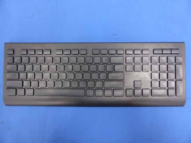
OO9KB313W
May 06, 20152.4GHz Wireless Keyboard
Equipment Class
DXX - Part 15 Low Power Communication Device Transmitter