OO9KPR04Wireless Keypad
G.Tech Technology Ltd.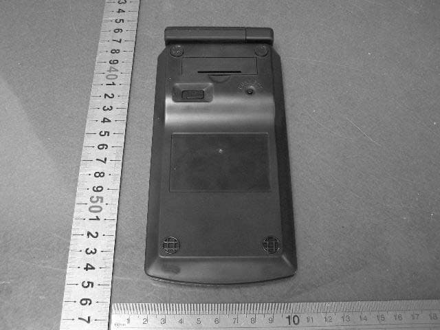
Click to zoom
Application Details
- Equipment Class
- DXX - Part 15 Low Power Communication Device Transmitter
- Date of Grant
- Sep 27, 2006
- Application Purpose
- Original Equipment
- Date of Application
- Sep 27, 2006
- Equipment Note
- Wireless Keypad
- Frequency Range
- 27.04500000 - 27.04500000
- Company
- G.Tech Technology Ltd.
- Country
- China
Documents & Files
Document Text
Text extracted from the exhibit documents filed with the FCC. Open a document above to read the original.
Users Manual
KPR04 (Wireless Keypad) & R0415 (Wireless Keypad and Wireless Mouse receiver) USER MANUAL Introduction System Requirements Hardware Operating System Setup Installing the Batteries Connecting the Receiver Setting the Identification Code Instruction MULTI MEDIA BUTTON instruction Content INTRODUCTION Introduction Congratulations on your purchase of this wireless keypad and mini mouse set. This set offers the latest technology for interference-free operation with 27MHz wireless connection -- 4,096 IDs for keypad and 2048 IDs for mouse . The keypad and mini mouse set features on/off switch and auto power saving management for effective power conservation. This user’s guide describes how to connect the receiver to your computer, install default software drivers and set up the radio link. System Requirements To use the keypad and mini mouse set, your computer must meet the following hardware requirements and run one of the operating systems listed below: Hardware z PC with an Intel Pentium processor or equivalent z USB 1.1 interface Operating System z Windows 98/WinNT /Windows me /WinXP /Windows 2000 (Driver required in Win98 /WinNT) SETUP Installing the Batteries for the keypad and mouse z Remove the battery cover z Insert the supplied Maxell batteries, making sure that the positive (+) and negative (-) ends of each battery match the polarity indicators inside the battery housing. z Turn on the keypad and mouse by sliding the Power switch on the underside of the keypad and mouse . Connecting z Plug the USB receiver into an available USB port on your computer. z Follow any on-screen instructions to complete the default driver installation. z LED light of the receiver turns on . z You are now ready to set the identification code to establish a communication link with the receiver and mouse . Setting the Identification Code After your computer detects the USB receiver and the driver software is installed, you must set the ID code among the receiver,mouse and keypad before you can use it. z Press and release the setup key on the receiver. The LED is lit. z Press the connect key on the keypad. z Once the LED on the receiver turns off, keypad and receiver is set up. z Press and release the setup key again on the receiver z Press the connect key on the mouse z Once the LED on the receiver turns off, the mouse is set up . z You are now ready to use the keypad and mini mouse set . NOTE: Make sure that your computer is turned on and has detected the USB receiver before you set the ID code. INSTRUCTION + : Volume up - : Volume down (上一首的标志) : Previous track (下一首的标志) : Next track (暂停和播放的标志) : Pause or play Mode : Switches between calculator and keypad modes Send : Send calculation results to your computer BS : Back space Del : Detes a number ( numlock off ) Ins : Emulates the inset key (numlock off ) End : Emulates the end key (numlock off ) : Moves the cursor down one line of text (numlock off) PgDn : Emulates the page down key (numlock off) : Moves one character to the left of the cursor position (numlock off) : Enter into Windows (numlock off) : Moves one character to the right of the cursor position (numlock off) Home : Emulates the home key (numlock off ) : Moves the cursor up one line of text (numlock off) Pgup : Emulates the page up key (numlock off) Remarks : z To switch between Calculator and Keypad mode , press the Mode key , the mode you are in will be displayed on the LCD . z To turn off the keypad while in calculator mode , press the Numlock key . z The Numlock key on your computer will not affect the Numlock status of the keypad . Power management To extend the life of your batteries , power off the battery with the on/off switch located on the back of the keypad while traveling or when you’re not using it . Troubleshooting What do I do if the keypad doesn’t work? --Make sure that the polarity of the batteries is correct. The positive and negative ends of each battery must match the positive and negative connections in the battery housing. --Check that the receiver’s USB connector is firmly attached to the USB port on your computer. --Verify that the device drivers are installed. --Make sure you have set the identification code successfully. When I use the calculator/keypad, other wireless devices work more slowly or fail temporarily , what should I do ? --The calculator /keypad may cause interference with any cordless, radio-based device that operates at 27MHz, such as a telephone, bay monitor, or toy. To reduce interference, move the calculator / keypad’s receiver and the base unit of the affected device as far away from each other as possible. --You can also reset the calculator / keypad‘s identification code. What do I do if the response time of the calculator / keypad is slow or it intermittently stops working? Try one or more of the following: --Increase the distance between the receiver and the rest of your computer equipment. --Increase the distance between the receiver and the base units of other wireless device. --Turn off any wireless devices and their base units that are near the keypad’s receiver. --If you are using the keypad on a metal surface , move it and the receiver to a non-metal surface . Metals, such as iron, aluminum or copper, shield the radio frequency transmission and may slow down the keypad’s response time or cause the keypad to fail temporarily. --Replace the batteries. Contents z Wireless Keypad z Wireless mini mouse z USB Receiver z 1 x AAA Maxell battery for keypad and 2 x AAA Maxell batteries for mouse Notice: The receiver is only intended to be pluged to the USB port directly without extended cable connected. Only complied LPS AAA alkaline battery can be used. Caution: Risk for explosion if battery is replaced by an incorrect type. Dispose of used batteries according to the instructions. Only Brand "Duracell" battery can be used. Changes or modifications not expressly approved by the manufacturer could void the user's authority to operate the equipment. G.T…
Text truncated - open the document above for the full version.
Block Diagram
1 1 2 2 3 3 4 4 DD CC BB AA Date:Filename: Drawn TITLE:KPR04 block diagram Approved Confirmed by: by: by: Version GT-R0101-A NO. Key Input Data output VCC Data out O s c i l l a t o r 1 Power Amplification ANT Power control Key output K e y M a t r i x Reset Power control MCU VCC DC/DC Convertor BATTERY Channel Control Reset GND ID ID KEY DRIVER IC LCD 1.5V PDF created with FinePrint pdfFactory trial version http://www.fineprint.com
External Photos
Wireless mouse KPR04 external photo
Internal Photos
Wireless Keypad KPR04 internal photo
Operational Description
Page 1 of 1 Product Operation Description This product KPR04 is wireless keypad, which has a standard numeric keyboard and some multimedia keys. A LCD is used to display the number input. It uses one AAA batteries. The main function of KPR04 is modulating pressing keys message, transmitting RF signal to associated receiver. K2002 has one channel 27.045MHz. To setup the connection between the Keypad and the receiver, the Connect key on the bottom of the keypad and the Connect key of the receiver must be pressed at the same time.
Schematics
1 1 2 2 3 3 4 4 5 5 6 6 DD CC BB AA Date:Filename: Drawn TITLE: KPR04-SCH Approved Confirmed by: by: by: Version V12 1 J3 BAT+ 1 J4 BAT- L5 0406-220uH C6 22uF C9 22uF D7 1N5819 VCC BAT+ Vout 2 Vin 3 G N D 1 U5 TP331A R1 22K VCC C20 22pF C21 22pF OSC2 OSC1 XTAL1 XTAL2 1 2 3 Q1 9014 R4 22K R5 22K C2 1uF A0 1 A1 2 A2 3 VSS 4 SDA 5 SCL 6 WP 7 VCC 8 U4 S524A40X21-SCB0 VCC C1 0.1uF C8 0.1uF R15 22K C25 100pF 1 2 3 Q5 2SC2223A(F13) C4 0.1uF C5 0.1uF R2 100K R26 220R C27 1000pF 1 2 3 Q6 9014 C26 82pF C29 15pF VCC X1 27.045M C19 100pF R29 47R TXP TXD R27 22K L6 0.56uH C32 120pF C33 30pF C30 R18 47K VCC 1 2 3 4 SW11 SW-RST R6 10K C3 0.1uF VCC R0 SCL SDA /RST T6 SCL SDA 2 1 3 SW1 MSH-12N02 C10 10uF C7 0.1uF SEG7 1 SEG6 2 SEG5 3 SEG4 4 SEG3 5 SEG2 6 SEG1 7 SEG0 8 CS 9 RD 10 WR 11 DATA 12 VSS 13 OSCO 14 OSCI 15 VLCC 16 VDD 17 IRQ 18 BZ 19 BZ 20 COM0 21 COM1 22 COM2 23 COM3 24 SEG31 25 SEG30 26 SEG29 27 SEG28 28 SEG27 29 SEG26 30 SEG25 31 SEG24 32 SEG23 33 SEG22 34 SEG21 35 SEG20 36 SEG19 37 SEG18 38 SEG17 39 SEG16 40 SEG15 41 SEG14 42 SEG13 43 SEG12 44 SEG11 45 SEG10 46 SEG9 47 SEG8 48 U2 SL3204 LCD_WR SDA C11 0.1uF VCC 1 1 2 2 3 3 4 4 5 5 6 6 7 7 8 8 9 9 10 10 11 11 12 12 13 13 14 14 15 15 16 16 17 17 18 18 19 19 20 20 21 21 22 22 23 23 24 24 25 25 26 26 27 27 28 28 29 29 30 30 31 31 32 32 33 33 34 34 35 35 36 36 J2 LCD36 LCD_CS R16 1K /RST OSC1 OSC2 SCL SDA TXP LCD_CS VCC GND LCD_WR XTAL1 XTAL2 /RST SDA TXP TXD R1 C6 C5 C4 C3 C2 C1 R0 R3 R2 WR C8 C7 SCL WR SDA CS R17 22K R19 22K C31 120pF L7 10uH ANT1 T1 T2 T3 VSS 1 TCC 2 VDD 3 /INT 4 P50 5 P51 6 P52 7 P53 8 P60 9 P61 10 P62 11 P63 12 P64 13 VSS 14 P65 15 P66 16 P67 17 P70 18 P71 19 P72 20 P73 21 P74 22 P75 23 P76 24 P77 25 OSCO 26 OSCI 27 /ERSET 28 U1 EM78P447SAS C1 C2 C3 C4 C5 C6 C7 C8 R0 R1 R2 R3 GND R7 10K LCD_CS 1 2 3 Q2 9014 1 2 3 Q3 9014 R8 240K R11 1M R12 47K R9 180K R10 6.8M VCC BAT+ LowBAT LowBAT R4 R4 1 2 3 4 5 6 7 8 9 10 P1 10PIN R1 R2 R3 R0 C1 C2 C3 C4 C5 C6 1 2 SW2 Mode 1 2 SW3 Send 1 2 SW4 BS 1 2 SW5 V- 1 2 SW6 NextTrack 1 2 SW7 Play/Pause 1 2 SW8 Mute 1 2 SW9 V+ 1 2 SW10 PrevTrack C8 R3R2R1 C7 R3R1R0R4 X3 6.0M VCC R2R4 1 2 SW12 Stop R0 R3 C12 1000pF 1 2 3 4 P2 SIP4 R0 1 2 3 4 P3 SIP4 T4 T5 T7 T8 T9 T10 T11 T12 T13 T14 T15 T16 T17 T18 R13 10pF BAT+ 1 2 3 Q4 R14 R20 L3 C13 C15 C14 TXP L1 L2 VCC C16 T19 T20 T21 PDF created with FinePrint pdfFactory trial version http://www.fineprint.com
Test Report
Produkte Products Prüfbericht - Nr.: Test Report no.: 16008041 001 Seite 2 von 15 Page 2 of 15 TEST SUMMARY 5.1 CONDUCTED EMISSION FOR FCC PART 15 PER SECTION 15.207(A) RESULT: N/A 5.2 RADIATED EMISSION FOR FCC PART 15 PER SECTION 15.209(A) RESULT: Pass 5.3 FUNDAMENTAL AND HARMONICS RADIATED EMISSION FOR FCC PART 15 PER SECTION 15.227 RESULT: Pass Produkte Products Prüfbericht - Nr.: Test Report no.: 16008041 001 Seite 3 von 15 Page 3 of 15 Contents 1 GENERAL REMARKS................................................................................................................ 4 1.1 COMPLEMENTARY MATERIALS.............................................................................................. 4 2 TEST SITES...............................................................................................................................4 2.1 TEST FACILITIES..................................................................................................................... 4 2.2 LIST OF TEST AND MEASUREMENT INSTRUMENTS................................................................ 5 2.3 TRACE ABILITY........................................................................................................................ 5 2.4 CALIBRATION.......................................................................................................................... 5 2.5 MEASUREMENT UNCERTAINTY............................................................................................... 6 2.6 LOCATION OF ORIGINAL DATA................................................................................................ 6 2.7 STATUS OF FACILITY USED FOR TESTING................................................................................ 6 3 GENERAL PRODUCT INFORMATION........................................................................................ 6 3.1 PRODUCT FUNCTION AND INTENDED USE.............................................................................. 7 3.2 RATINGS AND SYSTEM DETAILS............................................................................................. 7 3.3 INDEPENDENT OPERATION MODES........................................................................................ 7 3.4 SUBMITTED DOCUMENTS........................................................................................................ 8 4 TEST SET-UP AND OPERATION MODE.................................................................................... 8 4.1 PRINCIPLE OF CONFIGURATION SELECTION.......................................................................... 8 4.2 TEST OPERATION AND TEST SOFTWARE................................................................................ 8 4.3 SPECIAL ACCESSORIES AND AUXILIARY EQUIPMENT............................................................ 8 4.4 COUNTERMEASURES TO ACHIEVE EMC COMPLIANCE......................................................... 8 4.5 TEST SET-UP............................................................................................................................. 9 5 TEST RESULTS E M I S S I O N .......................................................................................... 10 5.1 CONDUCTED EMISSION FOR FCC PART 15 PER SECTION 15.207(A) .................................. 10 5.2 RADIATED EMISSION FOR FCC PART 15 PER SECTION 15.209(A) ...................................... 11 5.3 FUNDAMENTAL AND HARMONICS RADIATED EMISSION FOR FCC PART 15 PER SECTION 15.227 ................................................................................................................................................ 12 6 PHOTOGRAPHS OF THE TEST SET-UP..................................................................................... 6 7 LIST OF TABLES....................................................................................................................... 6 8 LIST OF PHOTOGRAPHS........................................................................................................... 6 Produkte Products Prüfbericht - Nr.: Test Report no.: 16008041 001 Seite 4 von 15 Page 4 of 15 1 General Remarks 1.1 Complementary Materials All attachments are integral parts of this test report. This applies especially to the following appendix: Appendix 1: Test result 2 Test Sites 2.1 Test Facilities Shenzhen SMQ Shenzhen Bureau of Quality Technical Supervision Shenzhen Academy of Metrology and Quality Inspection Bldg, of Shenzhen Academy of Metrology and Quality Inspection Longzhu Road, Nanshan, Shenzhen, P.R. China Produkte Products Prüfbericht - Nr.: Test Report no.: 16008041 001 Seite 5 von 15 Page 5 of 15 2.2 List of Test and Measurement Instruments Table 1: List of Test and Measurement Equipment Kind of Equipment Manufacturer Type S/N Calibrated until EMI Test Receiver Rohde & Schwarz ESI26 838786/013 29.01.2007 Signal Generator Rohde & Schwarz SMR20 100047 29.01.2007 Bilog Antenna Chase CBL6112B 2591 29.01.2007 3m Semi-anechoic chamber Albatross Projects 9X6X6 ---- 29.01.2007 Loop Antenna Schwarzbeck FMZB1516 113 29.01.2007 2.3 Trace ability All measurement equipment calibrations are traceable to NIST or where calibration is performed outside the United States, to equivalent nationally recognized standards organizations 2.4 Calibration Equipment requiring calibration is calibrated periodically by the manufacturer or according to manufacturer’s specifications. Additionally all equipment is verified for proper performance on a regular basis using in house standards or comparisons. Produkte Products Prüfbericht - Nr.: Test Report no.: 16008041 001 Seite 6 von 15 Page 6 of 15 2.5 Measurement Uncertainty The estimated combined standard uncertainty for conducted emissions measurements is ± 3 dB. The estimated combined standard uncertainty for radiated emissions measurements is ± 3 dB. 2.6 Location of original data The original copies of all test data taken during actual testing were attached at Appendix 1 of this report and deliver…
Text truncated - open the document above for the full version.
Test Setup Photos
Produkte Products Prüfbericht - Nr.: Test Report no.: 16008041 001 Seite 13 von 15 Page 13 of 15 6 Photographs of the Test Set-Up Photograph 1: Set-up for Radiation Measurement Below 30MHz Produkte Products Prüfbericht - Nr.: Test Report no.: 16008041 001 Seite 14 von 15 Page 14 of 15 Photograph 2: Set-up for Radiation Measurement below 1GHz
Contact Information
Applicant
Sulia Li(Certified Associate)
Test Firm
Shenzhen Academy of Metrology & Quality InspectionPeter Lin
Technical Specifications
| # | Rule Parts | Frequency Range | Power Output |
|---|---|---|---|
| 1 | 15C | 27.045 MHz - 27.045 MHz | - |
Other Applications from G.Tech Technology Ltd.
OO9P729
Aug 06, 2026WIRELESS GAMING MOUSE
Equipment Class
DTS - Digital Transmission System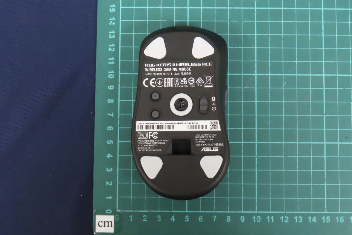
OO9P714
May 09, 2024GAMING MOUSE
Equipment Class
DTS - Digital Transmission System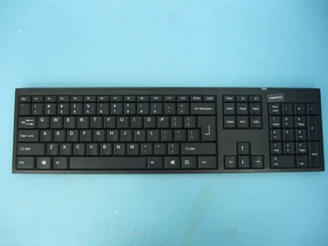
OO9GK381
Jun 17, 20152.4GHz Wirteless Keyboard
Equipment Class
DXX - Part 15 Low Power Communication Device Transmitter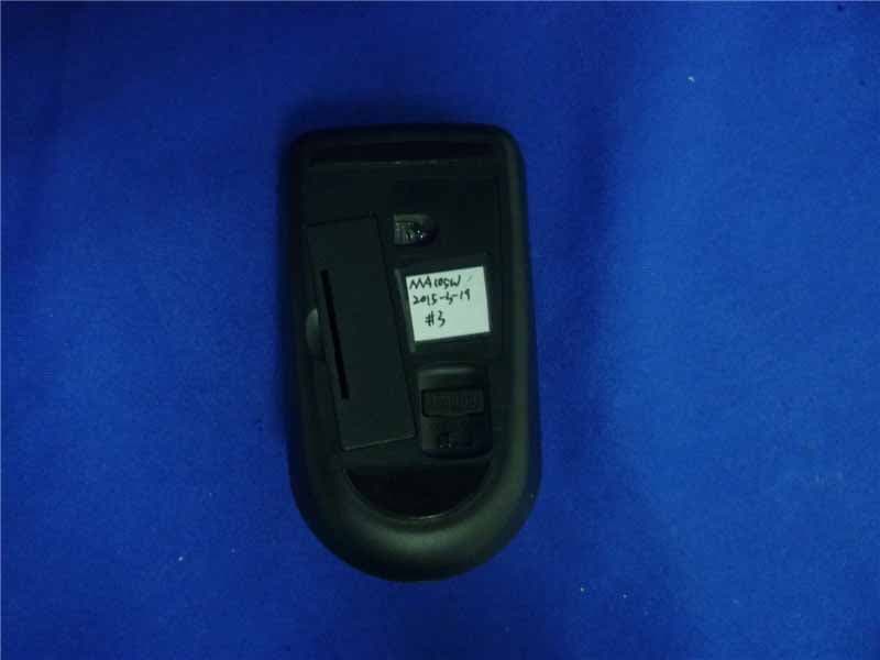
OO9MA105W
May 06, 20152.4GHz Wireless Mouse
Equipment Class
DXX - Part 15 Low Power Communication Device Transmitter
OO9KB313W
May 06, 20152.4GHz Wireless Keyboard
Equipment Class
DXX - Part 15 Low Power Communication Device Transmitter