OO9P2301BWireless Mouse
G.Tech Technology Ltd.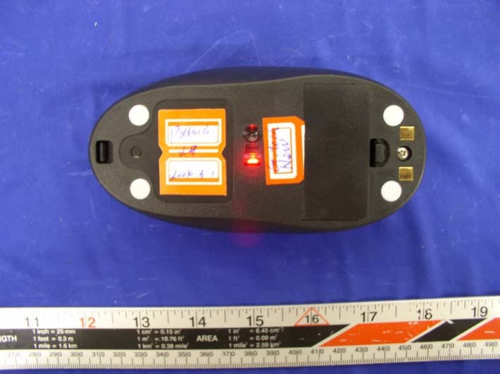
Click to zoom
Application Details
- Equipment Class
- DXX - Part 15 Low Power Communication Device Transmitter
- Date of Grant
- Apr 20, 2004
- Application Purpose
- Original Equipment
- Date of Application
- Apr 20, 2004
- Equipment Note
- Wireless Mouse
- Frequency Range
- 26.96000000 - 27.28000000
- Company
- G.Tech Technology Ltd.
- Country
- China
Documents & Files
Document Text
Text extracted from the exhibit documents filed with the FCC. Open a document above to read the original.
Users Manual
Wireless Keyboard Slim English - 1 - Wireless radio keyboard and radio mouse The wireless keyboard and optical mouse operate with digital radio technology. There is no connecting cable to hinder communication between the keyboard, the mouse and your computer. The keyboard and mouse need not be in the line of sight to the receiver. The keyboard and mouse use radio frequencies to send data to the receiver, which forwards these to your computer. You can use the keyboard and mouse on any computer equipped with a free USB interface. CE marking This equipment complies with the requirements of Directive 1999/5/EC of the European Parliament and Commission from 9 March 1999 governing Radio and Telecommunications Equipment and mutual recognition of conformity. This device is approved for use in Belgium, Denmark, Germany, Finland, France, Greece, Great Britain, Ireland, Iceland, Italy, Luxembourg, the Netherlands, Norway, Austria, Portugal, Sweden and Spain. Installing the batteries i Under all circumstances only use batteries and rechargeable batteries of the same type. The cordless optical mouse uses 2×AAA rechargeable batteries. 1. Remove the battery compartment cover on the bottom of the mouse. 2. Insert 2×AAA rechargeable batteries in the battery compartment. A diagram in the battery compartment shows correct installation. 3. The mouse will echo “BI” to show successful installation. 4. Carefully place the cover back into place. Wireless Keyboard Slim English - 2 - The cordless keyboard uses 2×AAA batteries. 1. Remove the battery compartment cover on the bottom of the cordless keyboard. 2. Insert 2× AAA batteries. A diagram in the battery compartment shows the correct installation. 3. Carefully place the cover back into place. Connecting the receiver 1. Connect the receiver's cable to the USB port of your computer and follow the instructions displayed on screen. 2. Set up the receiver at least 20 cm away from other electronic devices, such as the computer monitor or external storage drives to achieve optimum performance. i Maintain a distance – even in office environments – with the keyboard, mouse and receiver of at least 5 meter from other radio device to prevent interference during transmission of the signals. Setting up the ID wireless link – Keyboard and Mouse ID wireless link will be set up separately SLIM KEYBOARD 1. Press the connection button “CONNECT” on the receiver after booting the system. Indicator RX lights. 2. To set up the keyboard wireless link, press the RESET button on the bottom of the slim keyboard. Indicator RX light will be off. OPTICAL MOUSE 1. Press the connection button “CONNECT” on the receiver after booting the system. Indicator RX lights . 2. To set up the mouse wireless link, press the RESET button on the bottom of the mouse. Indicator RX light will be off. i The setup must be completed within one minute. If setup time exceeds one minute, repeat procedure. CHRG CONNECT RX Wireless Keyboard Slim English - 3 - Change communication code The desktop has communication code to the computer to avoid the interference with other desktop. You have to change the code if there is any interference. The interference only exists when many sets of mouse & keyboard used at the same time. Keyboard and Mouse ID wireless link will be changed separately. i z For the primary setup, both two wireless linkages, one for receive r and mouse, another for receive and keyboard, should be completed. z The communication ID for mouse and keyboard can be changed separately. z The setup must be completed within one minute. If setup time exceeds one minute, repeat procedure. SLIM KEYBOARD 1. Press the connection button “CONNECT” on the receiver, Indicator RX lights. 2. Press the “RESET” button on the bottom of the slim keyboard. Indicator RX light will be off as soon as the linkage is completed. OPTICAL MOUSE 1. Press the connection button “CONNECT” on the receiver, Indicator RX lights. 2. Press the “RESET” button on the bottom of the mouse. Indicator RX light will be off as soon as the linkage is completed. Battery low warning Mouse will echo "DE DE" as the batteries slowly get weaker. The echo will continue to rise every 30 seconds, till batteries are charged or changed. From hearing the first “DE DE” on, the mouse can still be used for half an hour longer. Charging the rechargeable batteries - Quickly Charging Before using the mouse for the first time, place it in the charging unit of the receiver for approximately 2 hours to charge the rechargeable batteries. When the mouse echo battery low warning echo “DE DE”, it means the batteries are out of power. Please charge the rechargeable batteries in the receiver. Wireless Keyboard Slim English - 4 - i Caution: For recharging do not use dis-rechargeable batteries, only use rechargeable batteries. 1. Make sure the adaptor is connected with the power. 2. Put the mouse into the charging-stand (see pictures). 3. An echo “BI” sounded by the mouse indicates the beginning of recharging; another echo “BI” will be sounded after finishing the process. The “CHAG” light color is red when battery is being recharged, and it will turn into green when the battery is fully recharged. 4. The recharge power is available during the power off state of the computer, only if the input electricity is available. Installing the software To take advantage of all the features of your mouse and keyboard, please install the software that comes with the product. The software provided offers you several advantages: − Activation of the multimedia keys of your keyboard and operating display on the screen when the multimedia keys are pressed. − Various functions for the mouse. − Icons in the taskbar. 1. Turn on your computer and start Windows. 2. Insert the CD in the corresponding drive. The CD starts automatically. If this is not the case, start the “Setup” program from the CD. 3. Follow the on-screen instructions. Displaying keyboard modes In the Windows taskbar icons indicate whic…
Text truncated - open the document above for the full version.
Block Diagram
1234 A B C D 4321 D C B A Key Input Left Right Middle Scroll Input Up Down Data output VCC Data out Oscillator Power Amplification ANT Tx Power control Tx Power Control Connect key Sensor Detecting Movement Connect Movement VCC DC/DC Convertor BATTERY Osc1 Memory Memory P2301B Mouse Block Diagram TX 27.145MHz Charge And Low Battery Check Charge Input BUZZER PDF created with FinePrint pdfFactory trial version http://www.fineprint.com
External Photos
APPENDIX C - EUT PHOTOGRAPHS EUT –Top View EUT - Rear View
ID Label/Location Info
APPENDIX A - FCC PRODUCT LABELING AND WARNING STATEMENT FCC ID Label this device must accept any interference received, including interference that may cause undesired operation. (1) this device may not cause harmful interference, and (2) Operation is subject to the following two conditions: This device complies with Part 15 of the FCC Rules. FCC ID: OO9P2301B 1.0" 2.1875" Specifications: Text is black in color and is left justified. Labels are printed in indelible ink on permanent adhesive backing and shall be affixed at a conspicuous location on the EUT. Proposed Label Location on EUT Bottom of EUT, FCC ID Label Proposed Location Label Here
Internal Photos
EUT – Cover Off View EUT - Component View (I) EUT - Component View (II) EUT - Solder View (I) EUT - Solder View (II)
Operational Description
Description of P2301B Wireless Mouse Circuit The DC-DC switching circuit consisted of IC-U5(RT9261-33CX) and other components will provide +3.9V DC operating voltage. When the mouse is moving on the desktop ,the optical sensor IC-U1(ADNS-2051) receive the LED! Light reflected by the destop,then it send the signal to MCU-U3(JS5618). Pin No.3 ,pinNo.4 of U3 data signal TXD and control signal TXP send to modulate transistor Q2(9014) and oscillating audion Q1(2223Y) together . then combine as Coplitts Circuit and transmit. When the user move the mouse or any press of the mouse. Pin4 and Pin3 of MCU-U3 will lead out TXD data signal and TXP control signal, and transmit by surge circuit. Push the button of SW5, the ID code of the mouse will change. U2 (KS24C010) is the memorizer of MCU and store the ID code of the mouse. Q8(9014) is the reset circuit diaplasis circuit of MCU. Which connect together with the battery low detection IC-U9(RT9808-21CX), act as alter of connecting power, charging, charging competed etc. When Transistor of Q8 reset, the low power indicator IC-U9(RT9808-21CX) will driver Q13(MMBT3906) and the buzzer B1 will generate ‘BE” sound. When another battery low indicate IC-U5(XC61CN2402MR) detect the voltage of the battery drop below 2.4V, the output of Pin 1 will become low voltage, and Q11(MMBT3906) connect with IC-U6(NE4556) and other components nearby, start run the times base surge circuit. Every 40 seconds the buzzer and generate “BE BE” to alert as the mouse under low power situation. The battery low indicator IC-U5(XC61CN2402MR) and components nearby act as the stable fact charging circuit and control the input current of the batteries.
Operational Description
1, 2, 3, 4, 5, 6, 7, 8, 9~ lO~ ll~ 12~ 13~ 14~ IS, 16, 17, 18~ 19, 20, 21, 22, 23, P230lB Optical Mouse Technical Specification Keys: Three Buttons, One 3600 wheel Key Stoke life time: Left fright ~l,OOO,OOO Cycles Middle keys ~100,000 Cycles Wheel switch ~100,000 Cycles Contact method: Micro switch/wheel switch Movement detect mode: Optical sensor(Angilent) Report rate: 80 reports/s Resolution: 800 DPI Security Code: 2048 different security code RF Transmission mode(Test Conditions:Vcc=3.0V): FSK RF Transmission 27. 145MHz::l:2.5KHz Channel bandwidth 50KHz Modulation Deviation 3. OKHz~ 6 f~6. 5KHz Tx Emission Level: 60dBuV/m~E~~80dBuV/m at 3m Batteries 2 x AAA Size Operating Distance: ~1.5m in normal environment Power comsumption(Test Conditions:Vcc=3.0V): ~60mA (Active) ~1.5mA (After 18minute) Battery life: ~ 15 hours at Act i ve mode with Alkaline Batter Low battery Annunciator: 2.4V ::1:5% System Requirement: Win95/Win98/WinNT /WinMe/WinXP/Win2000 (Driver required in Win95/linNT) Mechanical Dimension: L:123mm W:65mm H:39mm Plastic Material: ABS Net weight: 76.5g Storage temperature: -40~~55~ Working temperature: 0~~40~ Operating humidity: 40\~901 PDF created with FinePrint pdfFactory trial version httD://www.fineDrint.com
Parts List/Tune Up Info
P2301B MOUSE BOM IDVALUEREFUNITRemark 1 2RR0603L000JTR501 3RR0603L470JTR321 4RR0603L100JTR421 5RR0603L221JTR281 6RR0603L102JTR16,R512 7RR0603L222JTR52,R532 8RR0603L472JTR49,R552 9RC-03K9101FC R40 1 10RR0603L103JT R20,R21,R22,R23,R24 5 11RR0603L223JT R1,R2,R3,R4,R5,R6,R7,R8,R9,R10, R11,R12,R13,R19 14 12RR0603L333JT R44 1 13RR0603L473JT R26,R27,R29,R30,R31 5 14RC-03K6802FC R39 1 15RR0603L104JTR251 16RR0603L184JTR481 17RR0603L224JTR14,R152 18RR0603L274JTR431 19RR0603L225JTR541 20RC-05K120JT R33,R34,R35,R36,R37,R38 6 21RC-05K331JT R41 1 22RC-05K471JTR171 23 24C1608C0G1H150JT000AC271 25C1608C0G1H270JT000AC261 26C1608C0G1H300JT000AC6,C7,C8,C21,C225 27C1608C0G1H101JT000AC15,C16,C18,C194 28C1608C0G1H221JT000AC401 29C1608X7R1H102KT000NC24,C252 30C1608Y5V1H104ZT000N C1,C2,C3,C4,C5,C10, C11,C12,C31,C36 10 31C1608Y5V1C105ZT000NC29,C302 32C1608Y5V0J475ZC321 33C2012X7R1E105KTC351 34TAJB226K010RNJC381 35CD11X-25V-10uF±20%C141 36CD11X-16V-22uF±20%C281 37CD11X-16V-100uF±20%C9,C132 38CD288H-25V-47uF±20%C171 39 40CMI321611U2R2KTL21 Resistor Capacitor Inductor 1/3 PDF created with FinePrint pdfFactory trial version http://www.fineprint.com P2301B MOUSE BOM 41EC36-8R2J-T5L31 42PK0608-221KL11 43 441N372R0D21 451N4007D31 461N5819D11 471N4148 D4,D6,D7,D8,D9,D10 6 48ZMM5V1ZW11 49 50KSC2223YQ11 519014Q2,Q7,Q8,Q9,Q105 52MMBT3906Q11,Q12,Q133 53 8550 Q3,Q4,Q5,Q64 54 55 Infrared LED HLMP-ED80 LED11P BIN 56 IC ADNS-2051 U11 57LED Cover B-SB-LED1 58 59NE556U61 60KS24C010U21 61RT9261-33CXU41 62XC61CN2402MRU51 63RT9808-21CXU91 64JS5618U31 65 66XZT 18.432M2X11 67XZT 6.00M2X21 68 69HC-49U/S 27.145MHzX41 70 71Micro switch KW10-01 SW1,SW2,SW3 3 72 Encoder CER-B3F-NB SW41 73Touch switch 2A055SW51 74 75 Jump JP100 SW61 Jump1、2PIN 76White Wire B-DYX-30-180-3ANT21 77 Buzzer ATE1206-03 B11 78 Linker PH2.54 1*4P L11.6/3.0 S/T PA-11 79 Linker PH2.54 1*5P L11.6/3.0 S/T PB-11 80Linker FH2.54*6.8 1*4P S/TPA-21 81Linker FH2.54*6.8 1*4P S/TPB-21 82PCB P2302BV21-PCB11 Transistor Crystal Oscillator Photoelectricity module Ceramic resonator Switch Other IC Diode 2/3 PDF created with FinePrint pdfFactory trial version http://www.fineprint.com P2301B MOUSE BOM 83PCB P2302BV21-PCB21 84 85 Up cover MP2302-011 86 Bottom coverP23021 87 Battery cover B-SB-DCM-71 88 Mouse wheel B-SB-LTGL1 89 Lens HDNS-2100 #0011 90 AAA Battery Unite Spring B-LJTH-71 91 AAA Battery Cathode SpringB-FJTH-71 92 Battery Positive SpringB-ZJTH-71 93 Charge Plate metal P2302-JCP 2 94 Wheel rubber ring B-SB-YWJQ1 95 Screw HBB 1.8*45 96 Screw HBB 2.6*101 97 "QC PASS" Label1 98 Black Wire B-DYX-26-50-11 99 Red WireB-DYX-26-60-21 100 Black WireB-DYX-26-30-11 101 Red Wire B-DYX-26-30-21 102 AAA batteries550mAh Ni-MH2 103 Bottom matB-SB-JD-69*64 Table:Auditing :Pass: Structural member 3/3 PDF created with FinePrint pdfFactory trial version http://www.fineprint.com
Schematics
123456 A B C D 654321 D C B A Date: Filename: E:\G-TECH 2003\P2302B\V21\P2301BV21.sch Drawn TITLE: P2301B-SCH Approved Confirmed by: by: by: Version V21 文 件 编 号 GT-D-R0101 GND 10 GND 12 PD 15 SDIO 16 SCLK 1 X A 2 X B 3 Y B 4 Y A 5 R_BIN 14 REFA 7 REFB 8 OSC_OUT 11 OSC_IN 9 XY_LED 6 V D D 1 3 U1 ADNS-2051 2 1 3 SW1 L 2 1 3 SW2 R 2 1 3 SW3 M A C B SW4 SW WHEEL A0 1 A1 2 A2 3 VSS 4 SDA 5 SCL 6 WP 7 VCC 8 U2 KS24C010 C1 0.1uF R1 22K R2 22K C6 30pF V+3.9 C9 100uF/16V C2 0.1uF X1 18.432MHZ C3 0.1uF R3 22K 1 2 3 X2 6.00MHZ C7 30pF C8 30pF R14 220K R15 220K PA4/VREF 1 PA5 2 PA6 3 PA7 4 VDD 5 OSC2 6 OSC1 7 PB0 8 RB1 9 PB2 10 PB3 11 CNTI 12 /RST 13 VSS 14 PA0 15 PA1 16 PA2 17 PA3 18 U3 JS5618 SDIO SCLK SCLK SDIO PD PD EPSCLK EPSCLK SDIO V+3.9 V+3.9 TXP TXD WELL1 WELL2 L_Key R_Key M_Key V+3.9 V+3.9 L_Key R_Key M_Key WELL1 WELL2 C10 0.1uF SW5 Reset R16 1K TXD V+3.9 R20 10K L1 PK0608-221K C13 100uF/16V D1 1N5819 R25 100K T1 C4 0.1uF R17 470 C14 10uF/25V C15 100pF C16 100pF LED1 HLMP-ED80 C17 CD288H-47uF/25V D2 1N372R0 R4 22K R5 22K R6 22K V+3.9 R7 22K R8 22K LX 3 G N D 1 OUT 2 U4 RT9261-33CX VDD 3 G N D 2 VOUT 1 U5 XC61CN2402MR R21 10K C18 100pF C19 100pF R28 220R 1 2 3 Q1 KSC2223Y C21 30pF C22 30pF R9 22K R29 47K R32 47R C11 0.1uF R30 47K C24 1000pF L2 2.2uH C23 30pF 1 2 ANT1 TXD TXP 2 13 SW6 * 1 2 3 Q2 9014 C26 27pF C27 15pF C25 1000pF V+3.9 X3 * X4 27.145M C28 22uF C12 0.1uF V+3.9 Q3 8550 R33 12R D3 1N4007 R39 68K R40 9.1K Q7 9014 R10 22K Q8 9014 R26 47K R11 22K R27 47K C29 1uF V+3.9 Reset Reset CHARGE R41 330R R22 10K R34 12R T8 Q4 8550 R35 12R R36 12R D4 1N4148 Q9 9014 R12 22K R43 270K R13 22K C31 0.1uF C5 0.1uF Q10 9014 R23 10K R31 47K CHARGE ZW1 5.1V T9 R24 10K Q5 8550 R37 12R R38 12R T10 V+3.9 C32 4.7uF T11 ZW2 * D5 * R18 * C30 1uF CHARGE T12 C20 * Q6 8550 Battery Battery R45 * Battery Battery Battery T13 C33 * C34 * R47 * D6 1N4148 TRIG 6 Q 5 R 4 CVolt 3 THR 2 DIS 1 V C C 1 4 G N D 7 U6ANE556 R44 33K R54 2.2M D7 1N4148 C38 22uF D8 1N4148 C35 1uF TRIG 8 Q 9 R 1 0 CVolt 11 THR 12 DIS 13 U6BNE556 R48 180K B1 ATE1206-03 R55 4.7K Q11 MMBT3906 R19 22K V+3.9 D9 1N4148 D10 1N4148 R42 100 CHARGE R51 1K CON CON R46 * L3 8.2uH VCC 2 G N D 3 OUT 1 U7 * 1 2 J1 CHARGE_IN C40 220pF T14 VCC 2 G N D 3 OUT 1 U9 RT9808-21CX Q12 MMBT3906 R50 000R V+3.8V+3.8 R52 2.2K Q13 MMBT3906 Battery C36 0.1uF C37 * CON VDD 3 G N D 2 VOUT 1 U8 * VCC 2 G N D 3 OUT 1 U10 * VCC 2 G N D 3 OUT 1 U11 * C39 * BAT+ BAT+ 1 ANT2 ANT=180mm R53 2.2K C41 * R49 4.7K T2 T3 T4 PDF created with FinePrint pdfFactory trial version http://www.fineprint.com
Test Report
FCC PART 15.227 EMI MEASUREMENT AND TEST REPORT For G.tech Technology Ltd. NO.21, JINDING INDUSTRIAL PARK, WEST JINFENG ROAD, TANGJIAWAN TOWN, XIANGZHOU DISTRICT ZHUHAI GUANGDON CHINA FCC ID:OO9P2301B 2004 -03-30 Note: This test report is specially limited to the above client company and product model only. It may not be duplicated without prior written consent of Bay Area Compliance Laboratory Corporation. This report must not be used by the client to claim product endorsement by NVLAP or any agency of the U.S. Government. This Report Concerns: Original Report Equipment Type: Transmitter, Wireless Mouse Test Engineer: Jerry Wang / Report No.: R0403155 (T) Test Date: 2004-03-17 Reviewed By: Ling Zhang / Prepared By: Bay Area Compliance Laboratory Corporation 230 Commercial Street Sunnyvale, CA 94085 Tel: (408) 732-9162 Fax: (408) 732-9164 G.tech Technology Ltd. FCC ID: OO9P2301B Report # R0403155(T) Page 2 of 11 FCC ID Per 15.227 Report TABLE OF CONTENTS GENERAL INFORMATION.......................................................................................................................................3 PRODUCT DESCRIPTION FOR EQUIPMENT UNDER TEST (EUT) ....................................................................................3 OBJECTIVE...................................................................................................................................................................3 RELATED SUBMITTAL(S)/GRANT(S).............................................................................................................................3 TEST METHODOLOGY..................................................................................................................................................3 TEST FACILITY.............................................................................................................................................................3 SYSTEM TEST CONFIGURATION ..........................................................................................................................5 JUSTIFICATION.............................................................................................................................................................5 SCHEMATICS AND BLOCK DIAGRAM............................................................................................................................5 EQUIPMENT MODIFICATIONS.......................................................................................................................................5 TEST SETUP CONFIGURATION......................................................................................................................................5 SUMMARY OF TEST RESULTS ...............................................................................................................................6 §15.203 - ANTENNA REQUIREMENT......................................................................................................................7 STANDARD APPLICABLE..............................................................................................................................................7 §15.205, §15.209, §15.227 - RADIATED EMISSIONS TEST....................................................................................8 MEASUREMENT UNCERTAINTY....................................................................................................................................8 EUT SETUP..................................................................................................................................................................8 TEST EQUIPMENT LIST AND DETAILS...........................................................................................................................8 TEST PROCEDURE........................................................................................................................................................9 CORRECTED AMPLITUDE & MARGIN CALCULATION.................................................................................................10 SUMMARY OF TEST RESULTS.....................................................................................................................................10 RADIATED EMISSIONS TEST RESULT DATA...............................................................................................................10 §15.227(B) - OUT OF BAND EMISSION .................................................................................................................11 G.tech Technology Ltd. FCC ID: OO9P2301B Report # R0403155(T) Page 3 of 11 FCC ID Per 15.227 Report GENERAL INFORMATION Product Description for Equipment Under Test (EUT) The G.tech Technology Ltd.’s product, model number: P2301B or the "EUT" as referred to in this report is a Wireless Mouse Transmitter. The EUT is measured approximately 4.75” L x 2.5” W x 1. 5” H. Powered by two 1.5V AAA battery. * The test data gathered are from production sample, serial number: P2301B001, provided by the manufacturer. Objective This Type approval report is prepared on behalf of G.tech Technology Ltd. in accordance with Part 2, Subpart J, and Part 15, Subparts A, B and C of the Federal Communication Commissions rules. The objective is to determine compliance with FCC rules, sec 15.203, 15.205, 15.209 and sec 15.227. Related Submittal(s)/Grant(s) No Related Submittals. Test Methodology All measurements contained in this report were conducted with ANSI C63.4-2001, American National Standard for Methods of Measurement of Radio-Noise Emissions from Low-Voltage Electrical and Electronic Equipment in the range of 9 kHz to 40 GHz. All radiated and conducted emissions measurement was performed at Bay Area Compliance Laboratory, Corp. Test Facility The Open Area Test site used by Bay Area Compliance Laboratory Corporation to collect radiated and conducted emission measurement data is located in the back parking lot of the …
Text truncated - open the document above for the full version.
Test Setup Photos
APPENDIX B - TEST SETUP PHOTOGRAPHS Radiated Emission - Front View Radiated Emission - Rear View
Contact Information
Applicant
Sulia Li(Certified Associate)
Test Firm
Bay Area Compliance LaboratoryJohn Chan
Technical Specifications
| # | Rule Parts | Frequency Range | Power Output |
|---|---|---|---|
| 1 | 15C | 26.96 MHz - 27.28 MHz | - |
Other Applications from G.Tech Technology Ltd.
OO9P729
Aug 06, 2026WIRELESS GAMING MOUSE
Equipment Class
DTS - Digital Transmission System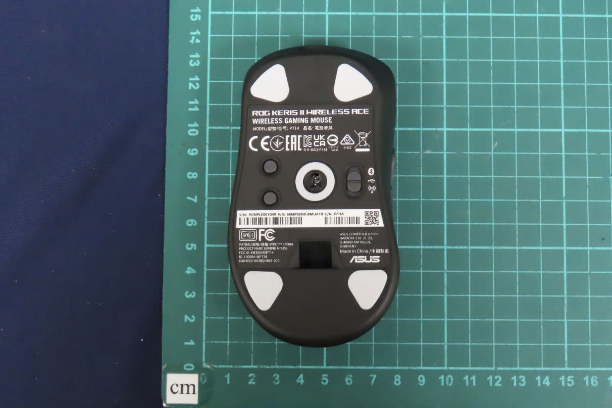
OO9P714
May 09, 2024GAMING MOUSE
Equipment Class
DTS - Digital Transmission System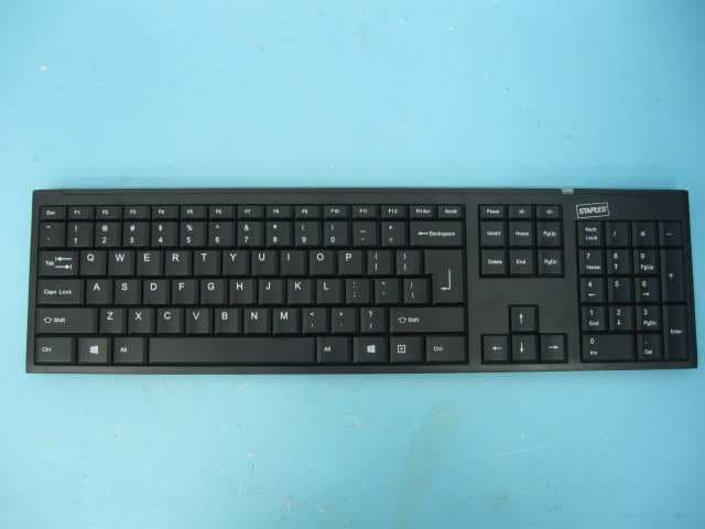
OO9GK381
Jun 17, 20152.4GHz Wirteless Keyboard
Equipment Class
DXX - Part 15 Low Power Communication Device Transmitter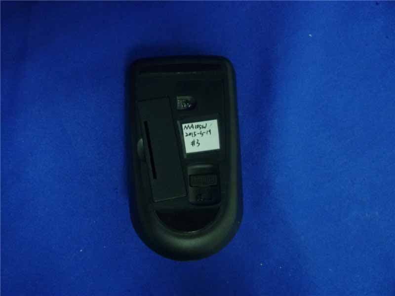
OO9MA105W
May 06, 20152.4GHz Wireless Mouse
Equipment Class
DXX - Part 15 Low Power Communication Device Transmitter
OO9KB313W
May 06, 20152.4GHz Wireless Keyboard
Equipment Class
DXX - Part 15 Low Power Communication Device Transmitter