OO9P6901Wireless Optical Mouse
G.Tech Technology Ltd.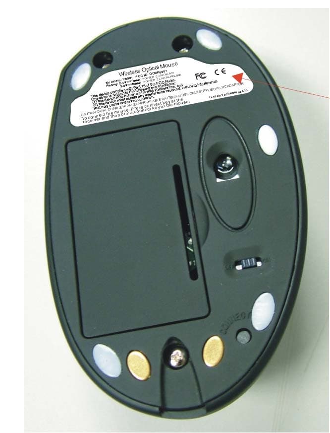
Click to zoom
Application Details
- Equipment Class
- DXX - Part 15 Low Power Communication Device Transmitter
- Date of Grant
- Mar 09, 2005
- Application Purpose
- Original Equipment
- Date of Application
- Mar 09, 2005
- Equipment Note
- Wireless Optical Mouse
- Frequency Range
- 26.96000000 - 27.28000000
- Company
- G.Tech Technology Ltd.
- Country
- China
Documents & Files
Document Text
Text extracted from the exhibit documents filed with the FCC. Open a document above to read the original.
Users Manual
- 1 - STANDARD MANUAL Thank you for your purchasing of Wireless Rechargeable Optical Mouse and keyboard. This USB combo is composed of 5-button mouse, 12-multimedia key keyboard and receiver with rechargeable function. Also we supply the power adaptor and rechargeable batteries for mouse for you. INSTALLING BATTERIES The wireless optical mouse uses two AA RECHARGEABLE batteries, the keyboard uses two AA batteries. Installing batteries for the mouse and keyboard as follow: 1、Open the battery compartment cover. 2、Insert the AA RECHARGEABLE batteries into the mouse battery compartments as indicated by the polarity symbols (+and-) marked inside, insert the AA batteries into the keyboard’s battery compartments as indicated by the polarity symbols (+and-) marked inside. 3、Replace the battery compartment covers. CONNECTING RECEIVER 1 、 Make sure your computer system is turned off. 2、Plug the USB port of receiver cable into the USB port of your computer. 3、Set up the receiver at least 20CM (8 inches) away from other electronic devices, such as monitor or external storage drives. 4、Start up your computer. SETTING UP THE ID WIRELESS LINK 1、Start up computer. 2、Press “connect” of receiver the indicator will light on and the receiver is successful to connection. 3、Press “connect” of keyboard the connection indicator light goes off, the keyboard is working. 4 、 Press “connect” of Mouse the connection indicator light goes off, the Mouse is working. A 1 OFF ON a. Please repeat step 2 to step 3 for the first use or changing batteries. b. Keyboard and Mouse will have a set of ID CODE to avoid interference when a lot of user in the same office, you should change the ID CODE as some occasionally interfering. (Please follow step 1,step 2 and step 3) c. “ A ” in the receiver is a capital mark, “ 1 ” is a number mark. INSTALLING THE SOFTWARE You can achieve the function without software under system Win/Me /2000/XP. To take advantage of all the features of your mouse and keyboard, please install the software that comes with the product. When installing the software please make sure that other drivers of other company are unloaded. 1、 Turn on your computer and start Windows; 2、 Insert the software of CD, run SETUP files of KEYBOARD and MOUSE. 3 、 Follow the on–screen instructions. A 1 PDF created with FinePrint pdfFactory trial version http://www.fineprint.com - 2 - SETTING THE CHANNEL The wireless keyboard and mouse offer 1 channels, CH1. The receiver automatically detects the channel of the mouse nd keyboard. If interference caused you can change the channel to avoid the interference. If you want to change the channel of mouse, operations as bellows: Press the CONNECT key on the bottom of the mouse, then press the CONNECT key on the receiver, then the mouse and receiver can achieve to change the channel. Note: every changing should be operated every 6 seconds OFF ON If you want change channel of keyboard, operations as follow: There is a channel switch on the bottom of the keyboard. If you want to use CH1, you only slide switch to CH1 it will be channel 1. CHECKING BATTERY POWER There are a low-power LED on keyboard and mouse. When the batteries are low, the LED will flash, when you should change new battery or recharge the rechargeable batteries of the mouse. low voltage indicator low voltage indicator Note: The LED can’t light when the keyboard batteries have no power. The LED on the bottom of the mouse will be off when the batteries are almost no power. And when you click the buttons of the mouse every time, the low-power LED will light. CH2CH1 PDF created with FinePrint pdfFactory trial version http://www.fineprint.com - 3 - RECHARGING THE BATTERIES When you find the batteries of the mouse are low power, you can recharge the rechargeable batteries according to the following steps: 1、Connect the adaptor to the receiver and connect the power. 2、Put the mouse into the charging-stand like the picture. 3 、 Low power LED is red as batteries are being charged. The indicator LED will turn to green, as batteries are fully charged. ( eight hours will be needed for first recharge) i. There is a Power switch on bottom of the mouse, when the button on “ON” it means fast charging, when the button on “OFF” it means slowly charging, the charging indicator LED is not on as slowly charging. ii. When your batteries are low power you can continue to use, as same time you need charging of mouse using adaptor directly by plugging the port to the ahead of the mouse , but the switch on the bottom of mouse must be set “ON”, the charging indicator will be light. (As the picture) MULTIMEDIA FUNCTIONS The buttons of keyboard have more functions. The keyboard will be Internet state after opening browser. Knock different button are different Web including Shopping and Finance and Search etc., these have icons on keyboard. The multimedia key can set-up by software as what you like, such as software what you like using can be set-up shortcut key. 1、 If you use Windows 98, please be sure install the driver enclosed the package before connecting the keyboard and mouse. 2、 You can achiever the multimedia function and not need to install the software if you use Microsoft Windows 2000/Me/XP/NT. 3、The button of F1~F12 have more functions, you can browsing International Net and check your email or work with other function so quickly. MOUSE WHEEL FUNCTION There is a wheel button on the mouse except left and right button. ● As a third key. ● It can be scrolled . When you scroll the wheel the file or the Web will be rolled. You can set-up function of the wheel button if you install the driver. PDF created with FinePrint pdfFactory trial version http://www.fineprint.com - 4 - ADDITIONAL BUTTON OF MOUSE There are two additional 4 and 5 on left side on mouse. The two buttons are using in page-up and page-down on acquiescence operating system. You can set-up this two button as you like when installing CD driver. POWER SWITCH ON THE MOUSE You can set…
Text truncated - open the document above for the full version.
Block Diagram
123456 A B C D 654321 D C B A Key Input Left Right Middle Scroll Input Up Down Data output VCC Data out Oscillator Power Amplification ANT Tx Power control Tx Power Control Connect key Sensor Detecting Movement Connect Movement VCC DC/DC Convertor BATTERY Crystal Annunciator Memory Memory CH1: 27.145MHz Charge LED LED Charge BATTERY BATTERY 27.145MHz P6901 Mouse Block Diagram PDF created with FinePrint pdfFactory trial version http://www.fineprint.com
External Photos
Wireless mouse P6901 external photo
Internal Photos
Wireless mouse P6901 internal photo
Operational Description
Product Operation Description This product P6901 is wireless optical mouse, which has five buttons: left button, mid-button, fourth and fifth buttons, the mid-button (wheel) functions both as a wheel and a button. The main function of P6901 is modulating button action and moving message, transmit RF signal to associated receiver. The operation frequency range is 26.96 to 27.28MHz, P6901 has one channel, then press CONNECT key on the bottom of the mouse, also you need to press CONNECT key on the receiver at the same time, the connection will be set up within one minute. The mouse P6901 has a battery-low indicator, which will light red when battery has low power, the light will be red while mouse is on charging, and turn green after finished charging, there is a power switch on bottom of the mouse, when the button is on “on” it means fast charging, when “off” it is slowly charging. Page 1 of 1
Schematics
123456 A B C D 654321 D C B A GND 10 GND 12 PD 15 SDIO 16 SCLK 1 X A 2 X B 3 Y B 4 Y A 5 R_BIN 14 REFA 7 REFB 8 OSC_OUT 11 OSC_IN 9 XY_LED 6 V D D 1 3 U1 ADNS-2051 2 1 3 SW1 L 2 1 3SW2 R 2 1 3SW3 M A0 1 A1 2 A2 3 VSS 4 SDA 5 SCL 6 WP 7 VCC 8 U2 S524A40X21-SCBO C1 0.1uF V+3.9 C16 100uF/16V C2 0.1uF X1 18.432MHZ C3 0.1uF R9 22K V+3.9 SW5 Reset L1 PK0608-221K C20 100uF/16V D1 1N5819 R16 100K T3 C4 0.1uF 2 1 3 SW6 K4 C21 10uF/25V LED2 HLMP-ED80 C24 CD288H-47uF/25V D3 1N372R0 2 1 3 SW7 K5 T8 T9 T10 T13 LX 3 G N D 1 OUT 2 U4 ME331C CHARGE GND V+3.9 CHARGE TOUCH 1 2 3 4 5 6 7 8 P1 8PIN 1 2 3 4 5 6 7 8 P2 8PIN V+3.9 T14 T15 ZW3 5.1V 12 SW9 POWER T1 1 2 3 J1 DS-313-023H T2 T4 V+3.9 R14 2.2K CHAR_LED R15 220 R21 27K R22 10M RF_TXD/Tdet CHAR_PWR R4 51K R23 220K R24 12K V+3.9 /RESET XTAL1 XTAL2 A C B SW4 SW WHEEL R25 220K R26 220K V+3.9 C26 100P C27 100P WHL1 WHL2 C28 10pF C29 10pF Y1 6.0MHz PB5/AN5 1 PB4/AN4 2 PA3/PFD 3 PA2 4 PA1 5 PA0 6 PB3/AN3 7 PB2/AN2 8 PB1/AN1 9 PB0/AN0 10 VSS 11 PC0 12 PC1 13 PD0/PWM 14 /RES 15 VDD 16 OSC1 17 OSC2 18 PA7/SCL 19 PA6/SDA 20 PA5/INT 21 PA4/TMR 22 PB7/AN7 23 PB6/AN6 24 U3 HT46R22/HT46C22 C6 0.1uF /RESET XTAL2 XTAL1 RF_TXD/Tdet RF_CH1 RF_CH2 FIF_KEY FOR_KEY R_KEY M_KEY L_KEYID_KEY WHL2 WHL1 CHARGE EPSCLK SCLKPD BUZZER CHAR_LEDV+3.9 SDA T11 T16 T17 Q6 S8550 CHARGE CHAR_PWR R17 470 VB+ R32 100R T18 SDA SCLK EPSCLK SDA ID_KEY FIF_KEY FOR_KEY R_KEY M_KEY L_KEY BAT1 Ni-MH BAT2 NiMH VB+ SCLK SDA PD Swi Swi VB+ Q7 8550 T19 T20 T21 1 2 3 Q8 9014 R37 10K R38 10K T22 R5 2.2K BUZZER R30 10K LED1 3RG9HW-1-1 Zyy Q9 9014 R33 10K R41 10K R42 47K CHAR_RX PD D7 1N4007 D8 1N4007 R20 4.7R 1W D6 1N4148 CHAR_RX CHAR_RX CHAR_RX 1 2 3 P3 SIP3 1 2 3 P4 SIP3 ID_KEY GND CHAR_RX 1 2 3 4 5 6 7 P5 7PIN 1 2 3 4 5 6 7 P6 7PIN CHAR_PWR R_KEY WHL1 WHL2 M_KEY L_KEY GND R31 6.8R R35 6.8R R36 6.8R R39 6.8R R40 6.8R T6 RF_CH1 RF_CH2 R6 22K C7 100pF C8 100pF R19 220R C11 0.1uF 1 2 3 Q1 KSC2223Y C12 15pF R43 47R R1 22K R11 100K R10 470R R12 47K C17 1000pF RF_CH2 RF_CH1 1 2 3 Q2 9014 C23 33pF C34 18pF C18 1000pF R34 68K V+3.9 X2 27.145M RF_TXD/Tdet C38 0.1uF L3 2.2uH L4 8.2uH C14 220pF C15 30pF C13 30pF L2 2.2uH R7 R8 10R R3 68K 1 2 3 Q10 KSC2223Y 1 ANT1 R44 2.2K R46 000R R45 2.2K Q11 9015 R50 100K Swi T5 R51 47K C25 22uF/16V C39 22uF/16V P6901-SCH PDF created with FinePrint pdfFactory trial version http://www.fineprint.com
Test Report
Produktsicherheit und –qualität Product Safety and Quality Prüfbericht - Nr.: Test Report No.: 16004610 001 Seite 2 von 16 Page 2 of 16 TEST SUMMARY 5.1 CONDUCTED EMISSION FOR FCC PART 15 PER SECTION 15.207(A) RESULT: ok 5.2 RADIATED EMISSION FOR FCC PART 15 PER SECTION 15.209(A) RESULT: ok 5.3 FUNDAMENTAL AND HARMONICS RADIATED EMISSION FOR FCC PART 15 PER SECTION 15.227 RESULT: ok Produktsicherheit und –qualität Product Safety and Quality Prüfbericht - Nr.: Test Report No.: 16004610 001 Seite 3 von 16 Page 3 of 16 Contents 1 GENERAL REMARKS.............................................................................................................. 4 1.1 COMPLEMENTARY MATERIALS............................................................................................ 4 2 TEST SITES............................................................................................................................. 4 2.1 T EST FACILITIES................................................................................................................... 4 2.2 LIST OF TEST AND MEASUREMENT INSTRUMENTS.............................................................. 5 2.3 TRACE ABILITY...................................................................................................................... 5 2.4 C ALIBRATION........................................................................................................................ 5 2.5 MEASUREMENT UNCERTAINTY............................................................................................. 6 2.6 LOCATION OF ORIGINAL DATA.............................................................................................. 6 2.7 S TATUS OF FACILITY USED FOR TESTING.............................................................................. 6 3 GENERAL PRODUCT INFORMATION...................................................................................... 7 3.1 P RODUCT FUNCTION AND INTENDED USE............................................................................ 7 3.2 RATINGS AND SYSTEM DETAILS........................................................................................... 7 3.3 INDEPENDENT OPERATION MODES...................................................................................... 7 3.4 S UBMITTED DOCUMENTS...................................................................................................... 8 4 TEST SET-UP AND OPERATION MODE.................................................................................. 8 4.1 PRINCIPLE OF CONFIGURATION SELECTION........................................................................ 8 4.2 T EST OPERATION AND TEST SOFTWARE.............................................................................. 8 4.3 S PECIAL ACCESSORIES AND AUXILIARY EQUIPMENT.......................................................... 8 4.4 C OUNTERMEASURES TO ACHIEVE EMC COMPLIANCE....................................................... 8 4.5 T EST SET-UP........................................................................................................................... 9 5 T EST RESULTS E M I S S I O N ........................................................................................ 10 5.1 CONDUCTED EMISSION FOR FCC PART 15 PER SECTION 15.207(A) ................................ 10 5.2 RADIATED EMISSION FOR FCC PART 15 PER SECTION 15.209(A).................................... 11 5.3 F UNDAMENTAL AND HARMONICS RADIATED EMISSION FOR FCC PART 15 PER SECTION 15.227 12 6 P HOTOGRAPHS OF THE TEST SET-UP................................................................................. 13 7 L IST OF TABLES................................................................................................................... 16 8 L IST OF PHOTOGRAPHS....................................................................................................... 16 Produktsicherheit und –qualität Product Safety and Quality Prüfbericht - Nr.: Test Report No.: 16004610 001 Seite 4 von 16 Page 4 of 16 1 General Remarks 1.1 Complementary Materials All attachments are integral parts of this test report. This applies especially to the following appendix: Appendix 1: Test result 2 Test Sites 2.1 Test Facilities Shenzhen SMQ Shenzhen Bureau of Quality Technical Supervision Shenzhen Academy of Metrology and Quality Inspection Bldg, of Shenzhen Academy of Metrology and Quality Inspection Longzhu Road, Nanshan, Shenzhen, P.R. China Produktsicherheit und –qualität Product Safety and Quality Prüfbericht - Nr.: Test Report No.: 16004610 001 Seite 5 von 16 Page 5 of 16 2.2 List of Test and Measurement Instruments Table 1: List of Test and Measurement Equipment Kind of Equipment Manufacturer Type S/N Calibrated until EMI Test Receiver Rohde & Schwarz ESI26 838786/013 29.01.2005 Signal Generator Rohde & Schwarz SMR20 100047 01.02.2005 Bilog Antenna Chase CBL6112B 2591 29.01.2005 3m Semi-anechoic chamber Albatross Projects 9X6X6 ---- 29.01.2005 Loop Antenna Schwarzbeck FMZB1516 113 31.01.2005 2.3 Trace ability All measurement equipment calibrations are traceable to NIST or where calibration is performed outside the United States, to equivalent nationally recognized standards organizations 2.4 Calibration Equipment requiring calibration is calibrated periodically by the manufacturer or according to manufacturer’s specifications. Additionally all equipment is verified for proper performance on a regular basis using in house standards or comparisons. Produktsicherheit und –qualität Product Safety and Quality Prüfbericht - Nr.: Test Report No.: 16004610 001 Seite 6 von 16 Page 6 of 16 2.5 Measurement Uncertainty The estimated combined standard uncertainty for conducted emissions measurements is ± 3 dB. The estimated combined standard uncertainty for radiated emissions measurements is ± 3 dB. 2.6 Location of original data The original copies of all test data taken during actual testing were attached at Appendix 1 of this report…
Text truncated - open the document above for the full version.
Test Setup Photos
Produktsicherheit und –qualität Product Safety and Quality Prüfbericht - Nr.: Test Report No.: 16004610 001 Seite 13 von 16 Page 13 of 16 6 Photographs of the Test Set-Up Photograph 1: Set-up for Continuous Disturbance Voltage on AC Mains Produktsicherheit und –qualität Product Safety and Quality Prüfbericht - Nr.: Test Report No.: 16004610 001 Seite 14 von 16 Page 14 of 16 Photograph 2: Set-up for Radiation Measurement Below 30MHz Produktsicherheit und –qualität Product Safety and Quality Prüfbericht - Nr.: Test Report No.: 16004610 001 Seite 15 von 16 Page 15 of 16 Photograph 3: Set-up for Radiation Measurement below 1GHz
Contact Information
Applicant
Sulia Li(Certified Associate)
Test Firm
Shenzhen Academy of Metrology & Quality InspectionPeter Lin
Technical Specifications
| # | Rule Parts | Frequency Range | Power Output |
|---|---|---|---|
| 1 | 15C | 26.96 MHz - 27.28 MHz | - |
Other Applications from G.Tech Technology Ltd.
OO9P729
Aug 06, 2026WIRELESS GAMING MOUSE
Equipment Class
DTS - Digital Transmission System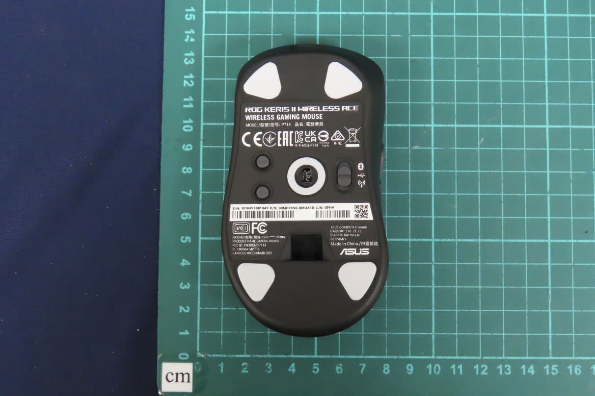
OO9P714
May 09, 2024GAMING MOUSE
Equipment Class
DTS - Digital Transmission System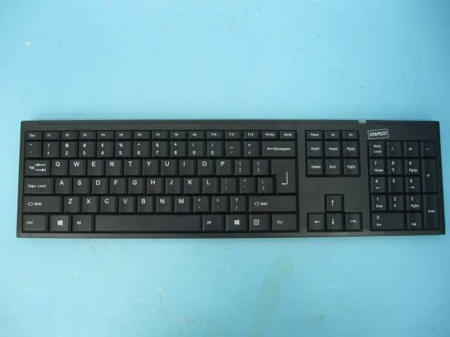
OO9GK381
Jun 17, 20152.4GHz Wirteless Keyboard
Equipment Class
DXX - Part 15 Low Power Communication Device Transmitter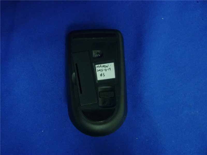
OO9MA105W
May 06, 20152.4GHz Wireless Mouse
Equipment Class
DXX - Part 15 Low Power Communication Device Transmitter
OO9KB313W
May 06, 20152.4GHz Wireless Keyboard
Equipment Class
DXX - Part 15 Low Power Communication Device Transmitter