OO9P7301Wireless Optical Mouse
G.Tech Technology Ltd.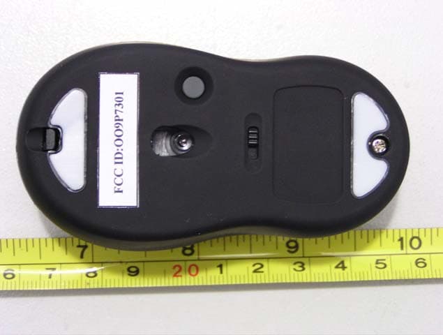
Click to zoom
Application Details
- Equipment Class
- DXX - Part 15 Low Power Communication Device Transmitter
- Date of Grant
- Nov 24, 2003
- Application Purpose
- Original Equipment
- Date of Application
- Nov 24, 2003
- Equipment Note
- Wireless Optical Mouse
- Frequency Range
- 26.96000000 - 27.28000000
- Company
- G.Tech Technology Ltd.
- Country
- China
Documents & Files
Document Text
Text extracted from the exhibit documents filed with the FCC. Open a document above to read the original.
Users Manual
BATTERY INSTALLATION 1. Press and hold the bottom release tab as you slide the top cover off. (Fig. 1) Fig. 1 2. Insert two AAA alkaline batteries. (Fig.1-2) Fig. 2 3. Replace the top cap and close it. Fig. 3 ! CAUTION: ·Be sure to check polarity (+ or – sign) and insert battery properly. ·Make sure battery type is AAA alkaline (1.5V). ·Remove the batteries if mouse will not be in use for a long time. ·Each time you replace the batteries, repeat the mouse setup by following the “setup for linkage” (Fig. 5) PDF created with FinePrint pdfFactory trial version http://www.fineprint.com HARDWARE INSTALLATION 1. Shut down the computer. 2. Connect the receiver either directly to the USB port on the PC. 3. Turn on the PC. 4. Switch on the power of the wireless mouse located on the backside of the mouse. (Fig. 4) ! CAUTION: ·While traveling, please switch off the unit to save battery power. (Fig. 4) Fig. 4 DRIVER INSTALLATION 1. Insert the installation CD into your CD_ROM drive. 2. The CD should automatically load the installation. Follow through the on-screen instructions to complete the installation. 3. When the setup is complete, the system will restart automatically. It will show a mouse icon in the bottom right-hand corner of the screen. ! CAUTION: Some computers running Windows 98 will require insertion of the Windows 98 CD to finish the installation of the driver. PDF created with FinePrint pdfFactory trial version http://www.fineprint.com ID SETUP 1. Aim the front point of the mouse at the receiver. 2. IMPORTANT: FISRT, PRESS THE CONNECT BUTTON OF THE MOUSE; THEN PRESS THE CONNECT BUTTON OF THE RECEIVER (Fig. 5). Fig. 5 3. When the connect button of the receiver is pressed, the LED inside the receiver will light. As soon as the linkage is completed, the LED will go off. 4. The setup must be completed within one minute. If setup time exceeds one minute, repeat procedure. BUTTON FUNCTION SETUP 1. Start the setup from the Control Panel or directly click on the mouse icon at the bottom right corner of the screen. It shows the following functions: -Button: set up for either right or left hand, and adjust the speed. -Wheel: set up the functions for hotkeys and zooming. -Motion: set up the speed of the mouse pointer. 2. After the function is set up, press “Yes” to store the PDF created with FinePrint pdfFactory trial version http://www.fineprint.com new setup. SETUP FOR MULTI-USERS When using more than one Mini Wireless Optical Mouse in the same location, set up one mouse at a time. You must complete the setup for each mouse before beginning the next. ENVIRONMENT To avoid environmental interference, which will shorten the effective operation distance, please note the following: 1. Do not put the mouse and receiver on a metal cabinet or desk. Metal creates RF interference, which may impair the RF communication and shorten the communication distance. 2. Keep a distance of more than 1.5m between your mouse and another operational RF device to avoid interference. 3. The optical sensor of the mouse will not work correctly if placed on a mirror, glass, or on any reflecting or half-tone painted process. TECCHNICAL SPECIFICATIONS Works with Windows 98, 2000, Me, or XP When using Windows 98 and setting up the mouse using a USB port, you may need your Windows 98 installation CD. PDF created with FinePrint pdfFactory trial version http://www.fineprint.com UNINSTALL INSTRUCTION 1. Go to “Start” then “Programs” and select “ G-Tech P74-USB”. 2. You should then see the uninstall option. Left-click on it. 3. Choose your desired language and click “OK”. 4. Then follow the on-screen instructions to complete the uninstall. FCC Compliance and Advisory Statement This hardware device complies with part 15 of the FCC Rules. Operation is subject to the following two conditions: 1) This device may not cause harmful interference, and 2) This device must accept any interference received, including interference that may cause undesired operation. This equipment has been tested and found to comply with the limits for a class digital device, pursuant to part 15 of the FCC rules, these limits are designed to provide reasonable protection against harmful interference in a residential installation. This equipment generates, uses and can radiate radio frequency energy and, if not installed or used in accordance with the instructions, may cause harmful interference to radio communications, however, there is no guarantee that interference will not occur in a particular installation, if this equipment does cause harmful interference to radio or television reception, PDF created with FinePrint pdfFactory trial version http://www.fineprint.com which can be determined by turning the equipment off and on, the user is encouraged to try to correct the interference by one or more of the following measures: 1) Reorient or relocate the receiving antenna; 2) Increase the separation between the equipment and the receiver; 3) Connect the equipment to an outlet on a circuit different from that to which the receiver is connected; 4) Consult the dealer or an experienced radio/TV technician for help. Any changes or modification not expressly approved by the party responsible for compliance could void the user's authority to operate the equipment. Where shielded interface cables have been provided with the product or specified additional components or accessories elsewhere that is defined to be used with the installation of the product, they must be used in order to ensure compliance with the FCC regulation. Caution: Exposure to Radio Frequency Radiation. The radiated output power of this device is far below the FCC radio frquency6 exposure limits Nevertheless, the device shall be used in such manner that the potential for human contact normal operation is minimized. When connecting an external antenna to the device, the antenna shall be placed in such a manner to minimize the potential for human contact during normal operation. In order to avoid p…
Text truncated - open the document above for the full version.
Block Diagram
1234 A B C D 4321 D C B A Key Input Left Right Middle Scroll Input Up Down Data output VCC Data out Oscillator Power Amplification ANT Tx Power control Tx Power control Connect key Sensor Detecting Movement Connect Movement VCC DC/DC Convertor BATTERY Osc1 Memory Memory P7301 Mouse Block Diagram TX 27.145 MHz PDF created with FinePrint pdfFactory trial version http://www.fineprint.com
External Photos
External Photos Transmitter Chassis - Top View Transmitter Chassis - Bottom View
ID Label/Location Info
ID Label Label FCC ID OO9P7301
ID Label/Location Info
ID Label/Location Label Location Information Specifications: Text is Black or white in color and is left justified. Labels are printed in indelible ink on permanent adhesive backing or silk-screened onto the EUT or shall be affixed at a conspicuous location on the EUT. Refer to the below arrow.
Internal Photos
Internal Photos Transmitter – Inside View Transmitter Chassis – Cover Off View Transmitter – Component View Transmitter – Component View Transmitter – Solder View
Operational Description
P7301 Mouse Circuit’s Operation Principle This circuit is mainly consisted of DC-DC convertor (IC-U4), MCU (IC-U3), photoelectric processor (IC-U1) and RF FSK circuit (Q1). Switching on the power controller SW6, IC-U4 provides the circuit with a stable 3.9V volts d.c. to keep the circuit working. When the mouse is moving on the desktop, photoelectric processor IC-U1 collect optical signals reflected by the desktop, and transfer them into electric signals, then input the electric signals into the MCU (IC-U3) to have these signals processed and managed. After that, these processed signals are outputted from the 4 th feet of the IC-U3to meet a control simultaneous signal produced by the 3 rd feet. Together, they are sent to the RF FSK circuit (Q1). to have transmitting modulation management. Similarly, when any key of the mouse is being operated, IC-U3 of MCU will make identification for the operation. Then, similarly, the 4 th feet of IC-U3 in the MCU output data and control signal to the RF FSK circuit (Q1). to carry out transmitting modulation management. IC-U3 is an E-P ROM storage that makes sure the circuit will keep working, by the way of keeping the ID code unchanged, when being out of power, changing the battery or being re-electrified. SW5 is a switch for ID code varying. PDF created with FinePrint pdfFactory trial version http://www.fineprint.com
Operational Description
P7301 Optical Mouse Technical Specification 1、 Model No. : P7301 2、 Key:Three Buttons, One 360°wheel 3、 Key Stoke life time: Left /right 1,000,000 Cycles Middle keys 100,000 Cycles Wheel switch 100,000 Cycles 4、 Mechanical Dimension 86.7mm x 45.4mm x 30mm 6 Mouse Report rate: 80 reports/s 7 Resolution: 800 DPI 8 System Requirement Windows 95/ Windows 98/ WinNT /Windows me/ Windows 2000/ Windows XP(Driver required in Win95/Win98/WinNT) 9 Plastic Material (ABS) 10 Net weight 41.5g 11 Security Code Mouse: 2048 different security code 12 RF Transmission mode: FSK 13 RF Receiver Center frequency: Mouse: 27.145MHz 14 Tx Emission Level: 60dBuV/m≤E 3m ≤80dBuV/m at 3m 15 Batteries: 2 x AAA Size 16 Battery life ≥20 hours at Active mode with Alkaline Batter 17 Operating Distance 1.5m in normal environment 18 Power consumption ≤45mA (Active) PDF created with FinePrint pdfFactory trial version http://www.fineprint.com
Schematics
123456 A B C D 654321 D C B A Date: Filename: E:\G-TECH 2003\P7301\V11\P7301V11.sch Drawn TITLE: P7301-SCH Approved Confirmed by: by: by: Version V11 文 件 编 号 GT-D-R0101 GND 10 GND 12 PD 15 SDIO 16 SCLK 1 X A 2 X B 3 Y B 4 Y A 5 R_BIN 14 REFA 7 REFB 8 OSC_OUT 11 OSC_IN 9 XY_LED 6 V D D 1 3 U1 ADNS-2051 V+3.9 12 SW1 L 12 SW2 R 12 SW3 M V+3.9 A C B SW4 SW WHEEL A0 1 A1 2 A2 3 VSS 4 SDA 5 SCL 6 WP 7 VCC 8 U2 KS24C010 C1 0.1uF R1 22k R2 22k C5 30pF V+3.9 C8 100uF/10V C2 0.1uF X1 18.432MHZ C3 0.1uF C9 10uF/16V R10 22K 1 2 3 X2 6.00MHZ C6 * C7 * R11 220K R12 220K PA4/VREF 1 PA5 2 PA6 3 PA7 4 VDD 5 OSC2 6 OSC1 7 PB0 8 RB1 9 PB2 10 PB3 11 CNTI 12 /RST 13 VSS 14 PA0 15 PA1 16 PA2 17 PA3 18 U3 JS5618 SDIO SCLK SCLK SDIO PD PD EPSCLK EPSCLK SDIO V+3.9 V+3.9 TXP TXD WELL1 WELL2 L_Key R_Key M_Key V+3.9 V+3.9 L_Key R_Key M_Key WELL1 WELL2 R3 22K R4 22K R5 22K C10 0.1uF SW5 Reset R13 1K TXD V+3.9 R14 10K L1 PK0406-221K C13 100uF/10V D1 1N5819 Battery R16 100K LX 3 G N D 1 OUT 2 U4 RT9261-33CX T1 T2 VCC 2 G N D 3 OUT 1 U5 * C4 * Battery R19 * TXD C14 2200pF C15 2200pF LED2 HLMP-ED80 C16 100uF/10V V+3.9 D3 1N372R0 R6 22K R7 22K T7 T8 T9 T10 R15 10K C17 100pF C18 100pF R20 220R 1 2 3 Q1 KSC2223Y C19 30pF C20 30pF R8 22K R21 47K R23 47R C11 0.1uF R22 47K C21 1000pF C12 0.1uF L2 2.2uH L3 8.2uH C23 220pF 1 ANT1 ANT=150mm TXD TXP C24 22uF/10V 1 2 3 Q2 9014 X3 27.145M C25 30pF V+3.9 C26 15pF C22 1000pF Q3 9014 R17 100K R9 22K R18 100K C27 1uF V+3.9 Reset Reset L4 * SP1 * T4 12 SW6 POWER PDF created with FinePrint pdfFactory trial version http://www.fineprint.com
Test Report
Note: This test report is specially limited to the above client company and product model only. It may not be duplicated without prior written consent of Bay Area Compliance Laboratory Corporation. This report must not be used by the client to claim product endorsement by NVLAP or any agency of the U.S. Government. FCC PART 15 SUBPART C EMI MEASUREMENT AND TEST REPORT For G.tech Technology Ltd. No.21,Jinding Industrial Park,West Jinfeng Road,TangJiawan Town,Zhuhai Guangdong China COMPTON, CA90220 FCC ID: 009P7301 November 14, 2003 This Report Concerns: Original Report Equipment Type: Wireless Optical Mouse Test Engineer: Ling Zhang / Report No.: RSZA03111101(T) Test Date: November 14, 2003 Reviewed By: Ming Jing / Prepared By: Bay Area Compliance Laboratory Corporation 230 Commercial Street Sunnyvale, CA 94085 Tel: (408) 732-9162 Fax: (408) 732-9164 G.tech Technology Ltd. FCC ID: 009P7301 Report # RSZA03111101(T) Page 2 of 15 FCC 15.227 Report TABLE OF CONTENTS 1 - GENERAL INFORMATION..................................................................................................................................3 1.1 PRODUCT DESCRIPTION FOR EQUIPMENT UNDER TEST (EUT) ..............................................................................3 1.2 OBJECTIVE.............................................................................................................................................................3 1.3 RELATED SUBMITTAL(S)/GRANT(S).......................................................................................................................3 1.4 TEST METHODOLOGY............................................................................................................................................3 1.5 TEST FACILITY.......................................................................................................................................................3 1.6 LOCAL SUPPORT EQUIPMENT LIST AND DETAILS...................................................................................................4 1.7 EXTERNAL I/O CABLES LIST AND DETAILS...........................................................................................................4 2 - SYSTEM TEST CONFIGURATION.....................................................................................................................5 2.1 JUSTIFICATION.......................................................................................................................................................5 2.2 SCHEMATICS AND BLOCK DIAGRAM......................................................................................................................5 2.3 EQUIPMENT MODIFICATIONS.................................................................................................................................5 2.4 TEST SETUP CONFIGURATION................................................................................................................................5 3 - SUMMARY OF TEST RESULTS..........................................................................................................................6 4 - RADIATED EMISSIONS TEST ............................................................................................................................7 4.1 MEASUREMENT UNCERTAINTY..............................................................................................................................7 4.2 EUT SETUP............................................................................................................................................................7 4.3 SPECTRUM ANALYZER SETUP................................................................................................................................7 4.4 TEST EQUIPMENT LIST AND DETAILS.....................................................................................................................7 4.5 TEST PROCEDURE..................................................................................................................................................8 4.6 CORRECTED AMPLITUDE & MARGIN CALCULATION.............................................................................................8 4.7 SUMMARY OF TEST RESULTS.................................................................................................................................8 4.8 RADIATED EMISSIONS TEST RESULT DATA...........................................................................................................9 4.9 BAND EDGE.........................................................................................................................................................10 4.10 OCCUPIED BANDWIDTH.....................................................................................................................................11 5 - CONDUCTED EMISSIONS .................................................................................................................................12 5.1 MEASUREMENT UNCERTAINTY............................................................................................................................12 5.2 EUT SETUP..........................................................................................................................................................12 5.3 SPECTRUM ANALYZER SETUP..............................................................................................................................12 5.4 TEST EQUIPMENT LIST AND DETAILS...................................................................................................................12 5.5 TEST PROCEDURE................................................................................................................................................12 5.5 TEST RESULTS SUMMARY....................................................................................................................................13 5.…
Text truncated - open the document above for the full version.
Test Setup Photos
Test Setup Photos Transmitter Radiated Emission Receiver Radiated Emission Conducted Emission
Contact Information
Applicant
Sulia Li(Certified Associate)
Test Firm
Bay Area Compliance Laboratory Corp. (Shenzhen)John Chan
Technical Specifications
| # | Rule Parts | Frequency Range | Power Output |
|---|---|---|---|
| 1 | 15C | 26.96 MHz - 27.28 MHz | - |
Other Applications from G.Tech Technology Ltd.
OO9P729
Aug 06, 2026WIRELESS GAMING MOUSE
Equipment Class
DTS - Digital Transmission System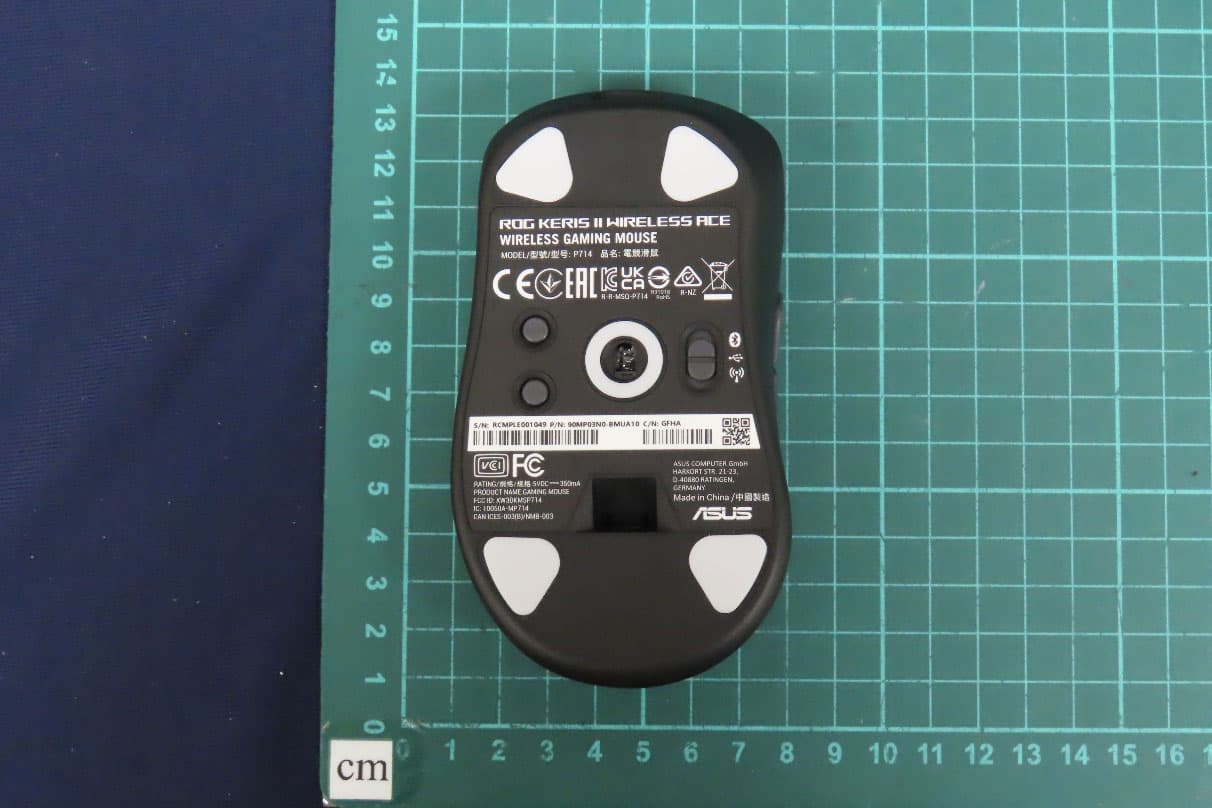
OO9P714
May 09, 2024GAMING MOUSE
Equipment Class
DTS - Digital Transmission System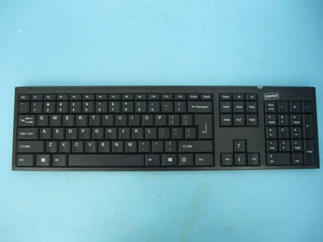
OO9GK381
Jun 17, 20152.4GHz Wirteless Keyboard
Equipment Class
DXX - Part 15 Low Power Communication Device Transmitter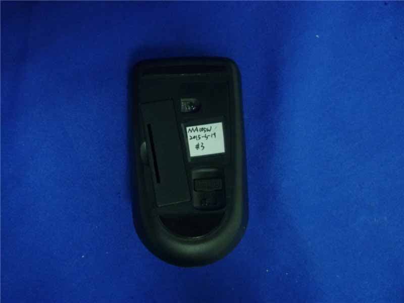
OO9MA105W
May 06, 20152.4GHz Wireless Mouse
Equipment Class
DXX - Part 15 Low Power Communication Device Transmitter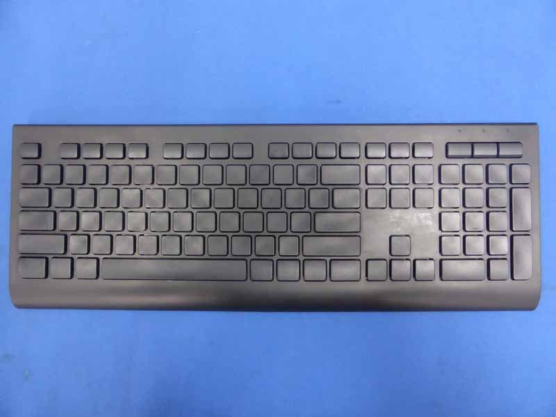
OO9KB313W
May 06, 20152.4GHz Wireless Keyboard
Equipment Class
DXX - Part 15 Low Power Communication Device Transmitter