OPPOBR5000B5 GHz Base Station Transceiver
Vecima Networks Inc.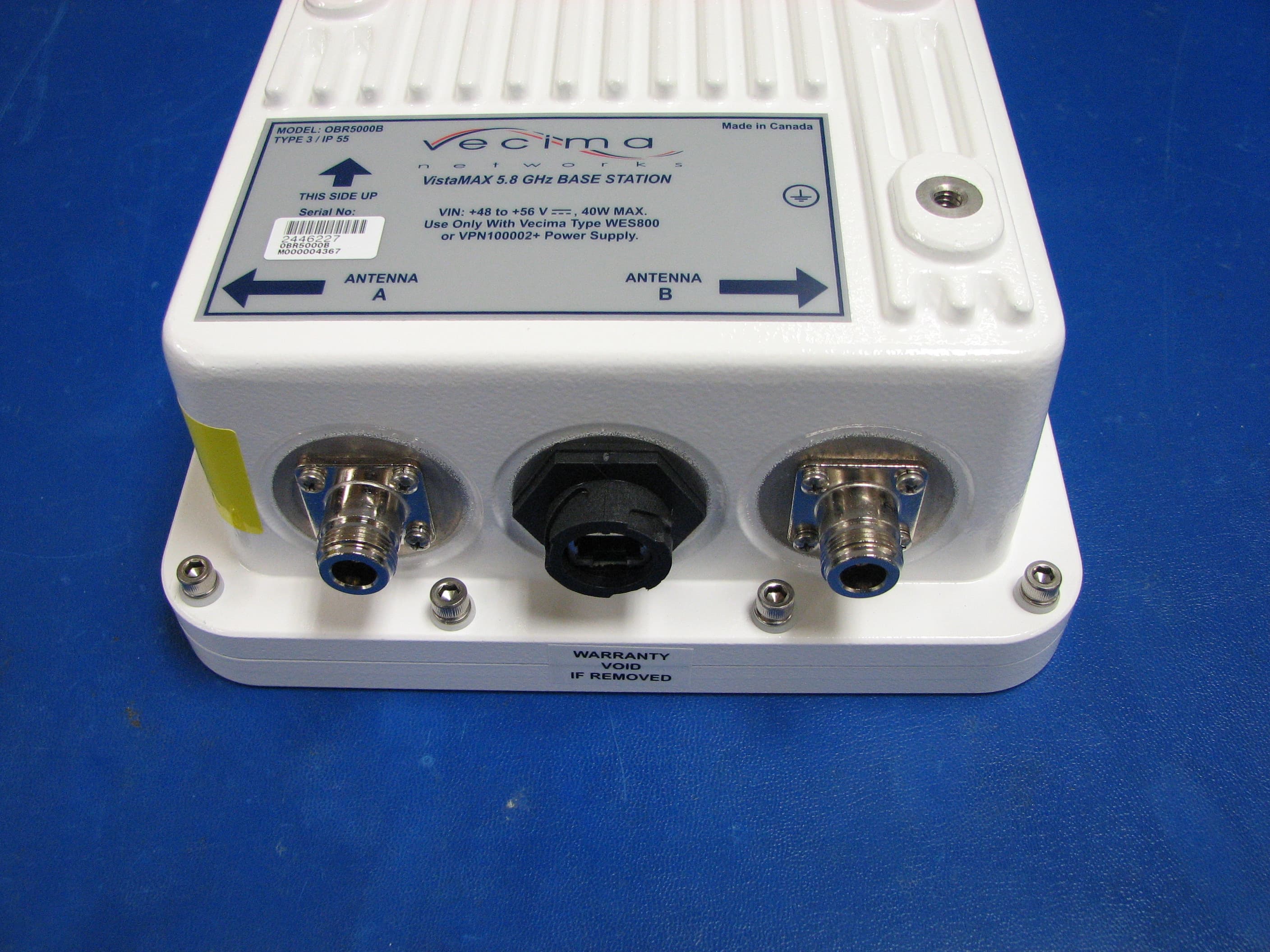
Click to zoom
Application Details
- Equipment Class
- NII - Unlicensed National Information Infrastructure TX
- Date of Grant
- Mar 14, 2010
- Application Purpose
- Original Equipment
- Date of Application
- Mar 11, 2010
- Equipment Note
- 5 GHz Base Station Transceiver
- Frequency Range
- 5740.00000000 - 5810.00000000
- Company
- Vecima Networks Inc.
- Country
- Canada
Documents & Files
Document Text
Text extracted from the exhibit documents filed with the FCC. Open a document above to read the original.
Users Manual
INSTALLATION AND OPERATION GUIDE VistaMax OBR5000B Base Station Transceiver Proprietary to Vecima Networks Inc. Copyright © 2007 Vecima Networks Inc. All rights reserved. No part of this publication may be reproduced in any form or by any means used to make any derivative work (such as translation, transformation or adaptation) without written permission from Vecima Networks Inc. Vecima Networks Inc. reserves the right to revise this publication and to make changes in content from time to time without obligation on the part of Vecima Networks Inc. to provide notification of such revision or change. Vecima Networks Inc. provides this guide without warranty of any kind, either implied or expressed, including, but not limited to, the implied warranties of merchantability and fitness for a particular purpose. Vecima Networks Inc. may make improvements or changes in the product(s) described in this manual at any time. Specifications subject to change without notice - Printed in Canada Document: Approved: obr5000b_ml_r01_sd D.W. obr5000b_ml_r01_sd Contents Preface.......................................................................................................................................................................................................................................... i About this Document.................................................................................................................................................................................................... i Safety and Regulatory Notices............................................................................................................................................................................... ii Warnings and Advisories................................................................................................................................................................................. iii Getting Support................................................................................................................................................................................................................ iv Finding Related Documentation................................................................................................................................................................... iv 1.0 Introduction......................................................................................................................................................................................................................... 1-1 1.1 Product Overview................................................................................................................................................................................................... 1-1 1.2 OBR5000B Features and Benefits.................................................................................................................................................................. 1-1 1.3 Specifications........................................................................................................................................................................................................... 1-2 2.0 Installation........................................................................................................................................................................................................................... 2-1 2.1 Unpacking the Unit................................................................................................................................................................................................ 2-1 2.2 Mounting the OBR5000B..................................................................................................................................................................................... 2-1 2.3 Attaching the External Antenna..................................................................................................................................................................... 2-7 2.3.1 Water Proof the Connection................................................................................................................................................................. 2-8 2.4 Installing the Grounding Apparatus............................................................................................................................................................. 2-9 2.4.1 Lightning Protection................................................................................................................................................................................. 2-9 2.4.2 Power Surge Protection......................................................................................................................................................................... 2-13 2.4.3 Grounding the Base Station................................................................................................................................................................. 2-15 3.0 Getting Started with OBR5000B............................................................................................................................................................................... 3-1 3.1 Before You Begin.................................................................................................................................................................................................... 3-1 3.2 Overview of Configuration................................................................................................................................................................................. 3-2 3.3 Using the Web Based Interface...................................................................................................................................................................... 3-2 3.4 Configuring the…
Text truncated - open the document above for the full version.
Users Manual
obr5000b_ml_r01_sdApproved: D.W. 2-14 2.4.2 Überspannungsschutz Verwenden Sie den Überspannungsschutz, um Ihr Gerät und Ihre Daten gegen Stromstösse zu schützen. So verbinden Sie die Kabelabschirmung mit dem Erdungsanschluss des Überspannungsschutzes: 1. Entfernen Sie die Abdeckung des Überspannungsschutzes. 2. Führen Sie das Ethernet-Kabel durch die Öffnung an der rechten Seite in den Überspannungsschutz ein. 3. Messen Sie ca. 12,5 cm (5 Zoll) vom Ende das Kabels, das Sie in die Öffnung eingeführt haben. 4. Ritzen Sie das Kabel am Messpunkt ein. 5. Schneiden Sie vorsichtig durch die Isolierung. Hinweis: Schneiden Sie NICHT durch die Metallabdeckung, die die Drähte umgibt. 6. Schneiden Sie die Isolierung bis zum Messpunkt ab. 7. Entfernen Sie die Isolierung vom Kabel. 8. Biegen Sie die Metallabdeckung in einen Erdungsstreifen. 9. Formen Sie mit den Drähten ein Durchgangskabel. Hinweis: Stellen Sie sicher, dass der Metallerdungsstreifen nicht beschädigt wird. 10. Lösen Sie den Erdungsbolzen an der rechten Seite des Überspannungsschutzes. 11. Wickeln Sie den Erdungsstreifen um den Erdungsbolzen. 12. Schrauben Sie den Erdungsbolzen wieder am Überspannungsschutz an. 13. Stecken Sie das PoE-Kabel (Power over Ethernet) durch die linke Öffnung in den Überspannungsschutz. 14. Formen Sie mit den Drähten ein Durchgangskabel. 15. Stecken Sie die Kabel in die entsprechenden Anschlüsse ein. 16. Bringen Sie die Abdeckung des Überspannungsschutzes wieder an. 17. Beenden Sie die Netzwerkverbindung. Siehe “Erden der Basisstation”. Figure 2-15 Abbildung 2.10: Montierter Überspannungsschutz obr5000b_ml_r01_sdApproved: D.W. 2-15 2.4.3 Grounding the Base Station Vecima recommends grounding the base station using one of the following procedures depending on your configuration. If you are unsure which procedure to use, use procedure B. Procedure A: Grounding the base station so that the building and the tower share the same earth ground: 1. Connect the chassis of the OBR5000B to the tower via the grounding lug on the back of the unit. See “Grounding the Base Station” on page 2-11. 2. Use a shielded CAT5 cablefeed to connect the OBR base station to the surge suppressor. 3. Use an inline surge suppressor for all OBR5000B cablefeed installations. Connect the shield of the cablefeed to the ground lug of the surge suppressor. The purpose of the surge suppressor is to shunt to ground any over volt - age [>60] transients that may be induced on the CAT5E cablefeed via lightning or other high voltages. Figure 2-16 Base Station Grounding - building ground is same as tower ground obr5000b_ml_r01_sdApproved: D.W. 2-16 Procedure B: Grounding the base station so that the building and the tower use different earth grounds: 1. Connect the chassis of the OBR5000B to the tower via the grounding lug on the back of the unit. See “Grounding the Base Station” on page 2-11. 2. Use a shielded CAT5 cablefeed to connect the OBR base station to the surge suppressor. 3. Use two inline surge suppressors, one for all OBR5000B cablefeed installations at the base of the tower and another for the first surge suppressor and the WES800. Connect the shield of the cablefeed to the ground lug of the surge suppressor. The purpose of the surge suppressor is to shunt to ground any over voltage [>60 V] tran - sients that may be induced on the CAT5E cablefeed via lightning or other high voltages. Figure 2-17 Base Station Grounding - building ground different than tower ground obr5000b_ml_r01_sdApproved: D.W. 2-17 2.4.3 Erden der Basisstation Vecima empfiehlt die Erdung der Basisstation abhängig von der Konfiguration mit einem der folgenden Verfahren. Wenn Sie nicht sicher sind, welches Verfahren geeignet ist, führen Sie Verfahren B aus. Verfahren A: Erden der Basisstation, damit das Gebäude und der Tower die gleiche Erdung verwenden: 1. Verbinden Sie das Gehäuse der OBR5000B über den Erdungsanschluss an der Rückseite mit dem Tower. Siehe "Erden der Basisstation" 2. Verwenden Sie eine abgeschirmte CAT5-Zuleitung, um die OBR-Basisstation mit dem Überspannungsschutz zu verbinden. 3. Verwenden Sie für alle OBR5000B-Zuleitungsinstalltionen einen Inline-Überspannungsschutz. Verbinden Sie die Abschirmung der Zuleitung mit dem Erdungsanschluss des Überspannungsschutzes. Der Überspannungsschutz überbrückt Überspannungen [>60 V], die in der CAT5E-Zuleitung durch Blitzschläge oder andere Hochspannun - gen verursacht werden können. Erdung der Basisstation Verfahren A: Gebäudeerdung = Turm-/Bodenerdung Abbildung 2-18: Erdung der Basisstation (die Gebäudeerdung entspricht der Towererdung) Abbildung 2-11: Erdung WES800 1. Das Überspannungselement sollte in der Nähe des Gebäudeeingangs montiert sein, entweder innen oder aussen 2. WES800 3. Gemeinsame Gebäudeerdung 4. Gemeinsame Bodenerdung 5. Anschluss zum NMS (Netzwerk Management Server), Router 6. Ungeschütztes Kategorie 5E Einspeisungskabel zwischen WiMAX Ethernet Switch 800 und Überspannungsschut- zelement 7. Geschütztes Kategorie 5E Kabel zwischen Überspannungsschutzelement und OBR (Aussenliegender Basissta- tion-Transceiver)xx00 8. Stellen Sie sicher, dass das geschützte Kategorie 5E Kabel an den OBR angeschlossen und richtig abgedichtet ist 9. Anschliessen des Chassis der OBRxx00 an den Turm durch Nutzung der Erdungshaltevorrichtung obr5000b_ml_r01_sdApproved: D.W. 2-18 Verfahren B: Erden der Basisstation, damit das Gebäude und der Tower unterschiedliche Erdungen verwenden: 1. Verbinden Sie das Gehäuse der OBR5000B über den Erdungsanschluss an der Rückseite mit dem Tower. Siehe "Erden der Basisstation" 2. Verwenden Sie eine abgeschirmte CAT5-Zuleitung, um die OBR-Basisstation mit dem Überspannungsschutz zu verbinden. 3. Verwenden Sie einen Inline-Überspannungsschutz für alle OBR5000B-Zuleitungsinstallationen am Unterteil des Towers und einen anderen Überspannungsschutz für den ersten Überspannungsschutz und die WES800. Erdung der Basisstation Verfahren B: Erden der Basisstation, damit das Gebäude und der Tower …
Text truncated - open the document above for the full version.
ID Label/Location Info
Vecima Proprietary and Confidential
Internal Photos
Vecima Proprietary and Confidential Vecima Proprietary and Confidential Vecima Proprietary and Confidential Vecima Proprietary and Confidential Vecima Proprietary and Confidential
Internal Photos
CtrlBoard CtrlBoard_Back CtrlBoard_SubBoard PwrBoard PwrBoard_Back SubBoard SubBoard-Back
RF Exposure Info
Prediction of MPE limit at a given distance ERM5 Equation from page 18 of OET Bulletin 65, Edition 97-01 where:S = power density P = power input to the antenna G = power gain of the antenna in the direction of interest relative to an isotropic radiator R = distance to the center of radiation of the antenna Maximum peak output power at device output terminal:21.39(dBm) Cable and Jumper loss0.0(dB) Maximum peak output power at antenna input terminal:21.39(dBm) Maximum peak output power at antenna input terminal:137.7209469(mW) Single Antenna gain(typical):12(dBi) Number of Antennae1 Total Antenna gain(typical):12(dBi) Maximum antenna gain:15.84893192(numeric) Prediction distance:20(cm) Prediction frequency:5775(MHz) MPE limit for uncontrolled exposure at prediction frequency:1(mW/cm^2) Power density at prediction frequency:0.434240(mW/cm^2) 4.342403(W/m^2) Maximum allowable antenna gain:15.62269855(dBi) Margin of Compliance:3.622698554dB 2 4R PG S π =
Test Report
www.nemko.com Nemko Canada Inc., 303 River Road, R.R. 5, Ottawa, Ontario, Canada, K1V 1H2 Report number: 134989-1TRFWL Apparatus: VistaMax OBR5000B Base Station Transceiver Applicant: Vecima Networks 150 Cardinal Place Saskatoon, SK, Canada S7L 6H7 FCC ID: OPPOBR5000B Test specification: Title 47-Telecommunication Chapter I - Federal Communications Commission Subchapter A - General Part 15 - Radio Frequency Devices Subpart E - Unlicensed National Information Infrastructure Devices − §15.407- General technical requirements Reviewed by: March 11, 2010 Signature Date Andrey Adelberg, Senior Wireless/EMC Specialist Tested by: David Duchesne, EMC/Wireless Specialist Nemko Canada Inc. authorizes the applicant to reproduce this report provided it is reproduced in its entirety and for use by the company’s employees only. Any use which a third party makes of this report, or any reliance on or decisions to be made based on it, are the responsibility of such third parties. Nemko Canada Inc. accepts no responsibility for damages, if any suffered by any third party as a result of decisions made or actions based on this report. This report shall not be reproduced except in full without the written approval of the testing laboratory. Nemko Canada Inc., a testing laboratory, is accredited by the Standards Council of Canada. The tests included in this report are within the scope of this accreditation. Report Number: 134989-1TRFWL Nemko Canada Inc., 303 River Road, R.R. 5, Ottawa, Ontario, Canada, K1V 1H2 Specification: FCC 15.407 Page 2 of 37 Table of contents Section 1: Report summary.....................................................................................................................3 Section 2: Equipment under test.............................................................................................................4 2.1 Identification of equipment under test (EUT)...........................................................................4 2.2 Accessories and support equipment.......................................................................................4 2.3 EUT description.......................................................................................................................5 2.4 Technical specifications of the EUT........................................................................................5 2.5 EUT setup diagram..................................................................................................................6 2.6 Operation of the EUT during testing........................................................................................6 2.7 Modifications incorporated in the EUT.....................................................................................6 Section 3: Test conditions.......................................................................................................................7 3.1 Deviations from laboratory tests procedures...........................................................................7 3.2 Test conditions, power source and ambient temperatures......................................................7 3.3 Measurement uncertainty........................................................................................................8 3.4 Test equipment........................................................................................................................8 Section 4: Result summary......................................................................................................................9 4.1 FCC Part 15 Subpart E, 15.407: Test results..........................................................................9 Appendix A: Test results........................................................................................................................10 Clause 15.31(e) Variation of the power source...................................................................................10 Clause 15.31(m) Number of operating frequencies............................................................................10 Clause 15.203 Antenna requirement...................................................................................................11 Clause 15.403(i) Emissions bandwidth...............................................................................................12 Clause 15.407(a)(3) Power limits (Output power and PPSD).............................................................15 Clause 15.407(a)(6) Power limits (Peak excursion)............................................................................19 Clause 15.407(b)(4) Undesirable emission limits (5.725 –5.825 GHz band)......................................21 Clause 15.407(b)(6) Undesirable emission limits (General field strength limits for frequencies below 1 GHz) and Clause 15.407(b)(7) Undesirable emission limits (provisions of §15.205) ..........................28 Clause 15.407(f) Radio frequency radiation exposure........................................................................35 Clause 15.407(g) Frequency stability..................................................................................................36 Appendix B: Block diagrams of test set-ups........................................................................................37 Section 1: Report summary Report Number: 134989-1TRFWL Nemko Canada Inc., 303 River Road, R.R. 5, Ottawa, Ontario, Canada, K1V 1H2 Specification: FCC 15.407 Page 3 of 37 Section 1: Report summary This report contains an assessment of apparatus against specifications based upon tests carried out on samples submitted at Nemko Canada Inc. Test specification: FCC Part 15 Subpart E, 15.407 Operation within the bands 5.25–5.35 GHz, 5.47–5.725 GHz and 5.725–5.825 GHz UNII bands. Compliance status: Complies Exclusions: None Non-compliances: None Report release history: Original release Test location: Nemko Canada Inc. 303 River Road, R.R. 5, Ottawa, Ontario, Can…
Text truncated - open the document above for the full version.
Test Setup Photos
§15.207 Conducted emissions Setup photos § 15.209 Radiated emission Setup photos
Contact Information
Applicant
Gus Medina(Compliance Engineer)
Technical Contact
Test Firm
Nemko Canada Inc. (Ottawa)Charles Neal
Technical Specifications
| # | Rule Parts | Frequency Range | Power Output |
|---|---|---|---|
| 1 | 15E | 5.74 GHz - 5.81 GHz | 137.70 mW |
Other Applications from Vecima Networks Inc.

OPP-AMG1020X
Dec 20, 2011Truckerlink Advanced Mobile Gateway
Equipment Class
DTS - Digital Transmission System
OPPTRX2526Y
Dec 18, 20112.5 GHz Subscriber Transceiver
Equipment Class
TNB - Licensed Non-Broadcast Station TransmitterOPPOBR3650HP
Jun 17, 2009VistaMAX OBR3650/HP+3.5 GHz Base Station Transceiver
Equipment Class
TNB - Licensed Non-Broadcast Station Transmitter
OPPMA4367
Sep 19, 2007MCS Transmitter / Upconverter System
Equipment Class
AMP - Amplifier
OPPTRX2525Y
Apr 26, 2007TRX2525Y 2.5-2.6 GHz Series Broadband Wireless Tx
Equipment Class
TNB - Licensed Non-Broadcast Station Transmitter