OPPTRI5758TRI5758 Integrated Broadband Wireless Transceiver
Vecima Networks Inc.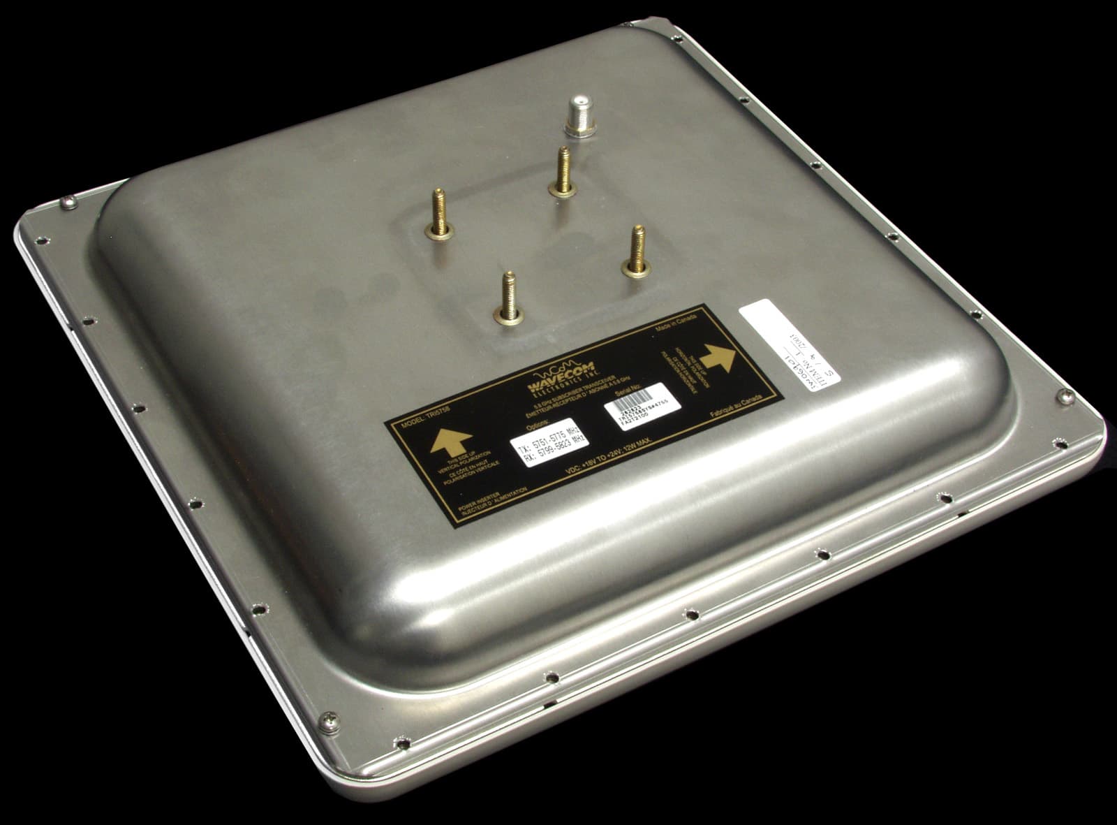
Click to zoom
Application Details
- Equipment Class
- NII - Unlicensed National Information Infrastructure TX
- Date of Grant
- Feb 12, 2004
- Application Purpose
- Original Equipment
- Date of Application
- Jun 18, 2003
- Equipment Note
- TRI5758 Integrated Broadband Wireless Transceiver
- Frequency Range
- 5725.00000000 - 5825.00000000
- Company
- Vecima Networks Inc.
- Country
- Canada
Documents & Files
Document Text
Text extracted from the exhibit documents filed with the FCC. Open a document above to read the original.
Users Manual
5.7-5.8 GHz Integrated Broadband Wireless Transceiver TRI5758 INSTALLATION AND OPERATION GUIDE FOR SYSTEM OPERATORS WaveCom Electronics Inc TRI5758 Manual; ML_TRI5758_03 (June 2003) Approval Pending ii Thank-you for purchasing this product and welcome to WaveCom! You have chosen an innovative broadband wireless solution from a leading technology design center in the ongoing TV & data delivery revolution. No doubt you’ve been thinking that the future of your television delivery system includes new technologies such as Digital TV, Internet Over Cable, Wireless Cable. By selecting WaveCom, you are benefiting from the same design powerhouse that since 1988 has created custom RF and digital products for technology leaders such as AT&T, Cisco Systems, Cogeco, Comcast, and Cox Communications. WaveCom designs and manufactures: 4 44 4Agile CATV Modulators 4 44 4256 QAM Upconverters 4 44 4Digital Video Modulators 4 44 4Frequency Translators 4 44 4Spread Spectrum Devices 4 44 4Off-Air Demodulators 4 44 4Video-On-Demand Products 4 44 4Wireless Cable MMDS 4 44 4Wireless Cable LMDS 4 44 4Frequency Stackers 4 44 4Subscriber Transceivers 4 44 4Satellite Receivers and more! Designs to fill the market needs of the CATV industry – both foreign and domestic. For additional product or corporate information, contact us: On the web at: www.WaveCom.ca By sending email to: [email protected] By telephone: (306) 955-7075 By fax: (306) 955-9919 By snail mail: WaveCom Electronics Inc. 150 Cardinal Place. Saskatoon, SK Canada S7L 6H7 WaveCom's Corporate Mandate is to be a leading worldwide designer and manufacturer of state- of-the-art communications equipment and c omponents. Through the remarkable success of our customers and business partners, WaveCom innovations are achieving this goal. WaveCom Electronics Inc TRI5758 Manual; ML_TRI5758_03 (June 2003) Approval Pending iii Proprietary to WaveCom Electronics Inc. All rights reserved. No part of this publication may be reproduced in any form or by any means or used to make any derivative work (such as translation, transformation or adaptation) without written permission from WaveCom Electronics Inc. WaveCom Electronics Inc. reserves the right to revise this publication and to make changes in content from time to time without obligation on the part of WaveCom Electronics Inc. to provide notification of such revision or change. WaveCom Electronics Inc. provides this guide without warranty of any kind, either implied or expressed, including, but not limited to, the implied warranties of merchantability and fitness for a particular purpose. WaveCom Electronics Inc. may make improvements or changes in the product(s) described in this manual at any time. TRI5758 Manual; ML_TRI5758_02 (May 2003); Approval Pending Specifications subject to change without notice — Printed in Canada WaveCom Electronics Inc TRI5758 Manual; ML_TRI5758_03 (June 2003) Approval Pending iv SAFETY PRECAUTIONS 1. Before installing and operating this equipment, read all Safety, Installation and Operating sections. Retain this manual for future reference. 2. Follow all instructions — Failure to do so may result in damage to the unit or severe personal injury. 3. The user should not attempt servicing. There are no user serviceable parts inside. Refer all servicing to factory qualified personnel. 4. Cleaning — Do not use liquid or aerosol cleaners. Use a damp cloth for cleaning. Warning Do not work on the system or connect or disconnect cables during periods of lightning activity. LES PRÉCAUTIONS DE SÉCURITÉ 1. Avant d'installer ou d'opérer cet équipement, lisez, toutes les sections de sécurités, d'installations et d'opérations. Gardez ce manuel comme source de référence. 2. Suivez toutes instructions - si non, vous risquez d'endommager la machine ou de vous blesser sérieusement. 3. N'essayez, pas de réparer cet équipement vous même. Référez toutes revisions nécessaire au personnel qualifié de la manufacture. 4. Le nettoyage - n'utilisez pas de nettoyeurs aérosols ou liquides. Utilisez un tissu humide pour nettoyer. Attention Ne pas travailler sur le système ni brancher ou débrancher les câbles pendant un orage du foudre. WaveCom Electronics Inc TRI5758 Manual; ML_TRI5758_03 (June 2003) Approval Pending v INFORMATION TO USER This device complies with Part 15 of the FCC Rules. Operation is subject to the following two conditions: (1) This device may not cause harmful interference, and (2) This device must accept any interference received, including interference that may cause undesired operation. This equipment has been tested and found to comply with the limits for Class B Digital Device, pursuant to Part 15 of the FCC Rules. These limits are designed to provide reasonable protection against harmful interference in a residential installation. This equipment generates and can radiate radio frequency energy and, if not installed and used in accordance with the instructions, may cause harmful interference to radio communications. However, there is no guarantee that interference will not occur in a particular installation. If this equipment does cause harmful interference to radio or television reception, which can be determined by turning the equipment off and on, the user is encouraged to try to correct the interference by one or more of the following measures: • Reorient or relocate the receiving antenna • Increase the separation between the equipment and receiver • Connect the equipment into an outlet on a circuit different from that to which the receiver is connected • Consult the dealer or an experienced radio/TV technician for help CAUTION: Any changes or modifications not expressly approved by WaveCom Electronics, Inc. could void the user’s authority to operate the equipment. CAUTION: This device must be professionally installed. WARNING: In order to comply with the FCC radiofrequency exposure limits of 1.1310, this equipment must be installed in such a way as to provide a minimum separation distance …
Text truncated - open the document above for the full version.
Attestation Statements
AAAFCC.jpg
Operational Description
T HE W AVE C OM TRI5758 B ROADBAND W IRELESS T RANSCEIVER WAVECOMELECTRONICSINC. 150 C ARDINALPLACE SASKATOON, SK, CANADA S7L 6H7 TEL: (306) 955-7075 FAX: (306) 955-9919 Website: www.WaveCom.ca E-mail: [email protected] Distributed by: Specifications subject to change without notice — Printed in Canada The TRI5758 is an Outdoor RF Transceiver for use in unliscenced broadband wireless systems. The TRI5758 combines a low noise downconverter, high power upconverter, antenna and high rejection duplexer to offer a fully integrated solution for 5.7 GHz BWIN TM BASED on DOCSIS TM subscriber terminals. The TRI5758 Integrated Subscriver Transceiver serves to freqency translate and amplify the upstream and downstream signals to the appropriate intermediate frequencies for use by the indoor DOCSIS modem. The TRI5758 with integral antenna is situated oudoors and connected to a cable modem indoors by a low cost 75 ohm cable (i.e. RG-59, RG-6 or similar. A single RF F- connector on the wetherproofed enclosure provides the interface to the indoor modem for rapid installation. br_tri5758_02 (May 2003) Product Features: •+28 dBm EIRP •Microprocessor controlled gain compensation over full temperature band •Automatic transmit RF mute (transmits only when an IF signal is present) •Integrated planar antenna •Audible installation alignment beeper to facilitate installation •Fully weatherized unit suited for outdoor mounting •Tx & Rx have excellent phase noise and frequency stability 150 CARDINALPLACE, SASKATOON, SK S7L 6H7 TEL: (306) 955-7075 FAX: (306) 955-9919 E- MAIL: [email protected]: WWW.WAVECOM.CA br_tri5758_02 (May 2003) Specifications subject to change without notice. - Printed in Canada. The DOCSISTM acronym belongs to CableLabs® S PECIFICATIONS—W AVECOMTRI5758 Broadband Wireless Transceiver T RANSMIT IF Input Frequency18 to 42 MHz RF Output Frequency5727 - 5751 MHz (Option T5727-5751R5775-5799) 5751 - 5775 MHz (Option T5751-5775R5799-5823) Gain (Integrated)26 dB +/- 2 dB Gain Flatness (Frequency Response)+/- 1 dB full band +/- 0.5 dB over any 6 MHz band Gain Stability over Temperature+/- 2.0 dB Linear Output Power+5 dBm into antenna (16 QAM, QPSK) Spurious (at transmit port)-40 dBm 9 kHz to 21.4 GHz Phase Noise< -85 dBc/Hz @ 10 KHz typical Spectral InversionNo spectral inversion Return Loss (IF)10 dB in Transmit and Receive bands IF Level for RF Activation+ 5 dBmV RF Activation/Mute Response Time<2 microseconds RECEIVE RF Input Frequency5775 - 5799 MHz (Option T5727-5751R5775-5799) 5799 - 5823 MHz (Option T5751-5775R5799-5823) IF Output Frequency516 -540 MHz Gain (Integrated)53 dB +/- 2 dB Gain Flatness (Frequency Response)+/- 1.5 dB full band +/- 0.5 dB any 6 MHz band Gain Stability over Temperature+/- 2.0 dB Noise Figure6.0 dB typical, 7dB max Image Rejection90 dB minimum Discrete Spurious (at IF port)-80 dBm between 510 and 546 MHz -50 dBm from 5 MHz to 510 MHz and from 546 MHz to 860 MHz Phase Noise (IF)<-85 dBc/Hz @ 10 kHz typical Spectral InversionNo spectral inversion G ENERAL Integrated Flat Panel Antenna Gain 23 dBi Beamwidth 9.0 degrees PolarityVertical or Horizontal Cross Polarization Isolation20 dB Front/Back Ratio30 dB Frequency Setting & Stability+/- 15 kHz (-30 to +40°C) Frequency Stability Over Time< +/- 25 kHz over 10 years IF ConnectorF female, 75 ohms DC Supply18 to 24 VDC, 12W max. Operating Temperature-30°C to +40°C (full specifications) -45°C to +45°C (operational) Size30.5 x 30.5 x 7.5 cm (12" x 12" x 3") MountingPole mount 1" to 2.5" dia. pole or wall mount with 90 deg pol, az and el adjustment Weight2.7kg max.
RF Exposure Info
Prediction of MPE limit at a given distance Equation from page 18 of OET Bulletin 65, Edition 97-01where: S = power density P = power input to the antennaG = power gain of the antenna in the direction of interest relative to an isotropic radiatorR = distance to the center of radiation of the antenna Maximum peak output power at antenna input terminal: 5.30 (dBm) Maximum peak output power at antenna input terminal: 3.388441561 (mW) Antenna gain(typical): 23 (dBi) Maximum antenna gain: 199.5262315 (numeric) Prediction distance: 20 (cm) Prediction frequency: 5725-5825 (MHz) MPE limit for uncontrolled exposure at prediction frequency: 1 (mW/cm^2) Power density at prediction frequency: 0.134502 (mW/cm^2) Maximum allowable antenna gain: 31.71269855 (dBi) Margin of Compliance at 30cm = 8.7dB 2 4 R PG S π =
Test Report
Master: PT15C-FHT Date: February 7, 2002 Test Report: 3W06901 Applicant: Wavecom Electronics Inc. 250 Cardinal Place Saskatoon, SK S7L 6H7 Equipment Under Test: TRI5758 Broadband Wireless Transceiver (EUT) 5.7-5.8GHz In Accordance With: FCC Part 15, Subpart E U-NII Devices Tested By: Nemko Canada Inc. 303 River Road, R.R. 5 Ottawa, Ontario K1V 1H2 Authorized By: Kevin Carr, EMC Specialist Date: 18 June 2003 Total Number of Pages: 49 Nemko Canada Inc. FCC PART 15, SUBPART E U-NII Devices PROJECT NO.:3W06901 EQUIPMENT: TRI5758 Page 2 of 49 Table of Contents Section 1. Summary of Test Results ...................................................................................3 Section 2. General Equipment Specification......................................................................5 Section 3. Powerline Conducted Emissions........................................................................8 Section 4. Emission Bandwidth .........................................................................................15 Section 5. Peak Conducted Transmit Power....................................................................22 Section 6. Peak Power spectral density ............................................................................29 Section 7. Peak Excursion Measurement .........................................................................36 Section 8. Undesirable Emissions......................................................................................43 Section 9. Block Diagrams .................................................................................................47 Section 10. Test Equipment List ..........................................................................................49 Nemko Canada Inc. FCC PART 15, SUBPART E U-NII Devices PROJECT NO.:3W06901 EQUIPMENT: TRI5758 Page 3 of 49 Section 1. Summary of Test Results General All measurements are traceable to national standards. These tests were conducted on a sample of the equipment for the purpose of demonstrating compliance with Part 15, Subpart E, for U-NII devices. Radiated tests were conducted is accordance with ANSI C63.4-1992. Radiated emissions are made on an open area test site. A description of the test facility is on file with the FCC. THIS TEST REPORT RELATES ONLY TO THE ITEM(S) TESTED. THE FOLLOWING DEVIATIONS FROM, ADDITIONS TO, OR EXCLUSIONS FROM THE TEST SPECIFICATIONS HAVE BEEN MADE. See “ Summary of Test Data”. TESTED BY: _______________________________ DATE: 17 June 2003 Glen Westwell, Wireless Technologist Nemko Canada Inc. authorizes the above named company to reproduce this report provided it is reproduced in its entirety and for use by the company’s employees only. Any use which a third party makes of this report, or any reliance on or decisions to be made based on it, are the responsibility of such third parties. Nemko Canada Inc. accepts no responsibility for damages, if any, suffered by any third party as a result of decisions made or actions based on this report. This report applies only to the items tested. Nemko Canada Inc. FCC PART 15, SUBPART E U-NII Devices PROJECT NO.:3W06901 EQUIPMENT: TRI5758 Page 4 of 49 Summary Of Test Data Name Of Test Para. No. Result Powerline Conducted Emissions 15.207(a) Complies Emission Bandwidth 15.403(c) Complies Peak Conducted Transmit Power 15.407(a)(3) Complies Peak Power Spectral Density 15.407(a)(3) Complies Peak Excursion Measurement 15.407(a)(6) Complies Undesirable Emissions 15.407(b)(3)(5) Complies Test Conditions: Indoor Temperature: 22°C Humidity: 40% Outdoor Temperature: 22°C Humidity: 40% Nemko Canada Inc. FCC PART 15, SUBPART E U-NII Devices PROJECT NO.:3W06901 EQUIPMENT: TRI5758 Page 5 of 49 Section 2. General Equipment Specification Manufacturer: Wavecom Electronics Inc. Model No.: TRI5758 Serial No.: 282823 Date Received In Laboratory: 9 May 2003 Nemko Identification No.: #1 Frequency Band: 5.725-5.825GHz Operating Frequency(ies) of DUT: TX: 5.751-5.775GHz RX: 5.799-5.823GHz Transmit Power (Rated): +5dBm @ 2560 ksym/s +2dBm @ 1280 ksym/s -1dBm @ 640 ksym/s -4dBm @ 320 ksym/s -7dBm @ 160 ksym/s Antenna Gain (integral): 23dBi Modulation: 16 QAM QPSK Emission Designator: 3M10D1W 3M10G1W Nemko Canada Inc. FCC PART 15, SUBPART E U-NII Devices PROJECT NO.:3W06901 EQUIPMENT: TRI5758 Page 6 of 49 Nemko Canada Inc. FCC PART 15, SUBPART E U-NII Devices PROJECT NO.:3W06901 EQUIPMENT: TRI5758 Page 7 of 49 Transmitter Characterization Table & Set up Average Power at Antenna Port Data Rate (ksym/s) Rated Power 16 QAM (dBm) QPSK (dBm) Low Mid High Low Mid High 2560 +5dBm 5.0 4.9 4.8 5.0 4.8 4.8 1280 +2dBm 2.0 2.0 1.6 2.0 2.0 1.8 640 -1dBm -1.0 -1.0 -1.3 -1.0 -1.0 -1.4 320 -4dBm -4.0 -4.0 -4.3 -4.0 -4.0 -4.3 160 -7dBm -7.0 -7.0 -7.3 -7.0 -7.0 -7.3 Signal Gen AC/DC TRI5758 Power Meter H.P.E4418B Nemko Canada Inc. FCC PART 15, SUBPART E U-NII Devices PROJECT NO.:3W06901 EQUIPMENT: TRI5758 Page 8 of 49 Section 3. Powerline Conducted Emissions Para. No.: 15.207 (a) Test Performed By: Glen Westwell Date of Test: 28 May 2003 Test Results: Complies. Measurement Data: See attached table & graph(s). Nemko Canada Inc. FCC PART 15, SUBPART E U-NII Devices PROJECT NO.:3W06901 EQUIPMENT: TRI5758 Page 9 of 49 Comments: Project Number: 3w06901 LISN: EMCO FA001545 Date: May 28, 2003 Class B Mains limits (Phase) No. Frequency of Emission (MHz) Detector Emission Level (dBuV) LISN Loss (dB) Cable Loss (dB) Result (dBuV) Limit (dBuV) Margin (dB) Quasi-Peak 49.4 0.1 0 49.5 65.9 16.4 1 0.1518 Average 17.1 0.1 0 17.2 55.9 38.7 Quasi-Peak 49 0.1 0.2 49.3 65.4 16.1 2 0.1617 Average 16.7 0.1 0.2 17 55.4 38.4 Quasi-Peak 47.8 0.1 0.4 48.3 64.0 15.7 3 0.1897 Average 15.6 0.1 0.4 16.1 54.0 37.9 Quasi-Peak 46.7 0 0 46.7 62.6 15.9 4 0.2247 Average 14.4 0 0 14.4 52.6 38.2 Quasi-Peak 45.6 0 0.2 45.8 61.3 15.5 5 0.2649 Average 13.3 0 0.2 13.5 51.3 37.8 Quasi-Peak 41.6 0 0 41.6 58.0 16.4 6 0.3938 Average 9.3 0 0 9.3 48.0 38.7 Nemko Canada Inc. FCC PART 15, SUBPART E U-NI…
Text truncated - open the document above for the full version.
Test Setup Photos
Nemko Canada Inc. FCC PART 15, SUBPART E U-NII Devices PROJECT NO.:3W06901 EQUIPMENT: TRI5758 Page 8 of 49 Section 3. Powerline Conducted Emissions Para. No.: 15.207 (a) Test Performed By: Glen Westwell Date of Test: 28 May 2003 Test Results: Complies. Measurement Data: See attached table & graph(s).
Test Setup Photos
Nemko Canada Inc. FCC PART 15, SUBPART E U-NII Devices PROJECT NO.:3W06901 EQUIPMENT: TRI5758 Page 46 of 49 Radiated Test Set Up
Contact Information
Applicant
Gus Medina(Compliance Engineer)
Technical Contact
Nemko Canada Inc.Ruby Dulmage
613-737-9680
303 River Road · Ottawa, Ontario · Canada
Non-Technical Contact
Nemko Canada Inc.Ruby Dulmage
[email protected]613-737-9680
Test Firm
Nemko Canada Inc.Stuart Beck
Technical Specifications
| # | Rule Parts | Frequency Range | Power Output |
|---|---|---|---|
| 2 | 15E | 5.72 GHz - 5.83 GHz | 3.00 mW |
Other Applications from Vecima Networks Inc.

OPP-AMG1020X
Dec 20, 2011Truckerlink Advanced Mobile Gateway
Equipment Class
DTS - Digital Transmission System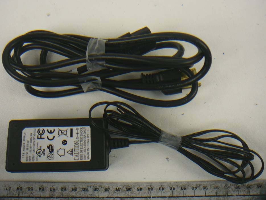
OPPTRX2526Y
Dec 18, 20112.5 GHz Subscriber Transceiver
Equipment Class
TNB - Licensed Non-Broadcast Station Transmitter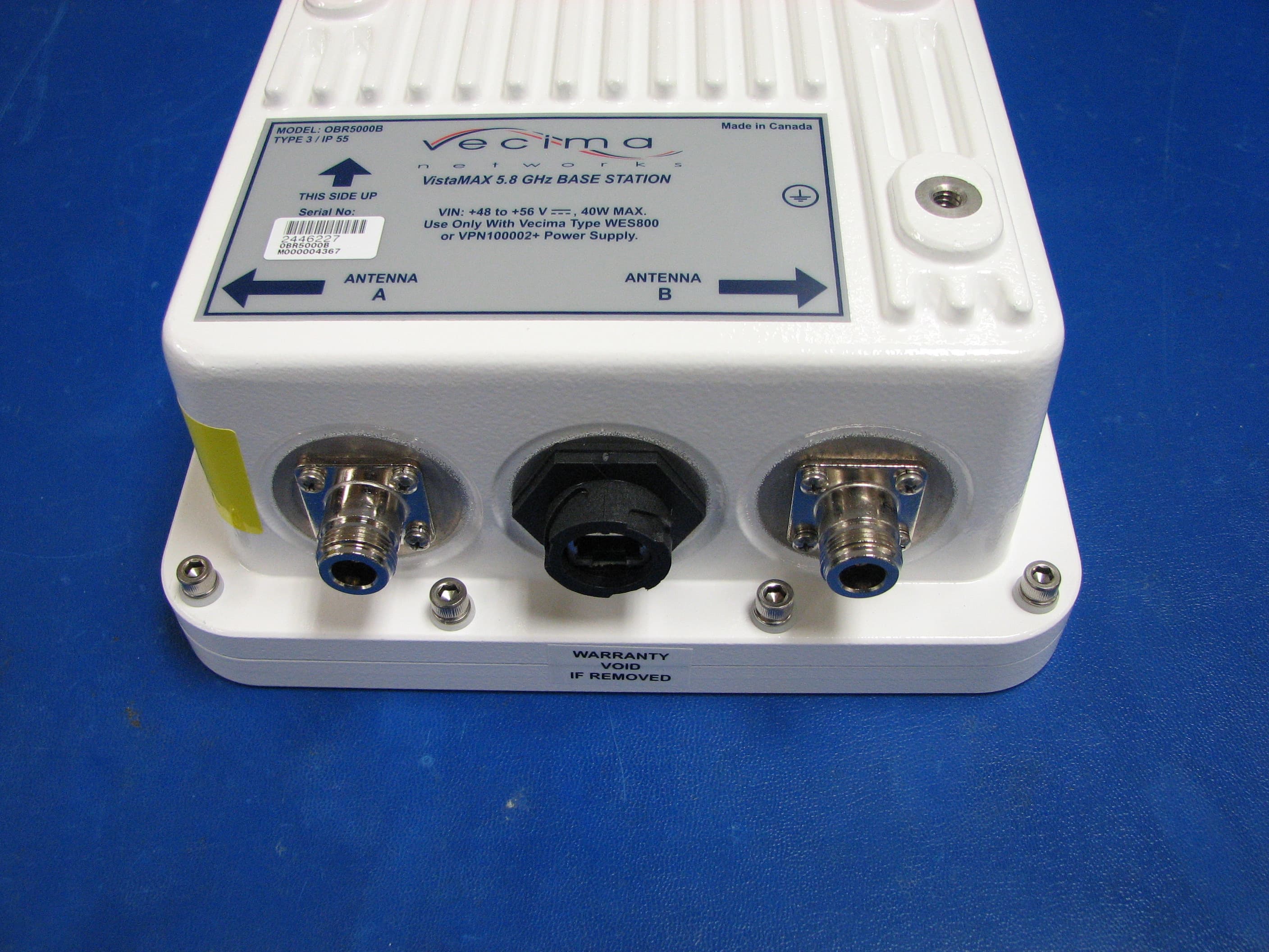
OPPOBR5000B
Mar 14, 20105 GHz Base Station Transceiver
Equipment Class
NII - Unlicensed National Information Infrastructure TXOPPOBR3650HP
Jun 17, 2009VistaMAX OBR3650/HP+3.5 GHz Base Station Transceiver
Equipment Class
TNB - Licensed Non-Broadcast Station Transmitter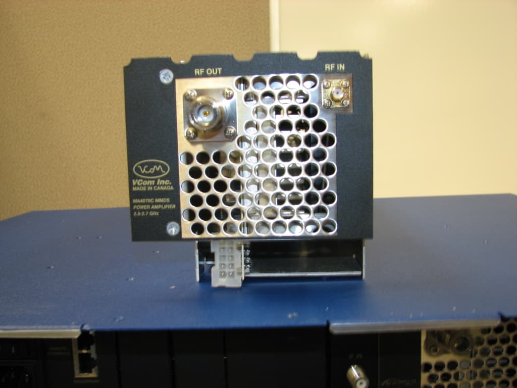
OPPMA4367
Sep 19, 2007MCS Transmitter / Upconverter System
Equipment Class
AMP - Amplifier