OQ7-IHNRLXIB-IHN, RLXIB-IHN-W, RLXIB-IHN-WC, RLXIB-IH2N, RLXIB-IH2N-W, & RLXIB-ICN
ProSoft Technology, Inc
Click to zoom
Application Details
- Equipment Class
- DTS - Digital Transmission System
- Date of Grant
- Nov 14, 2011
- Application Purpose
- Original Equipment
- Date of Application
- Jun 08, 2011
- Equipment Note
- RLXIB-IHN, RLXIB-IHN-W, RLXIB-IHN-WC, RLXIB-IH2N, RLXIB-IH2N-W, & RLXIB-ICN
- Frequency Range
- 5745.00000000 - 5825.00000000
- Company
- ProSoft Technology, Inc
- Country
- United States
Documents & Files
Document Text
Text extracted from the exhibit documents filed with the FCC. Open a document above to read the original.
Users Manual
RLXIB-IHN 802.11n Industrial Hotspot April 8, 2011 USER MANUAL Your Feedback Please We always want you to feel that you made the right decision to use our products. If you have suggestions, comments, compliments or complaints about our products, documentation, or support, please write or call us. How to Contact Us ProSoft Technology 5201 Truxtun Ave., 3rd Floor Bakersfield, CA 93309 +1 (661) 716-5100 +1 (661) 716-5101 (Fax) www.prosoft-technology.com [email protected] Copyright © 2011 ProSoft Technology, Inc., all rights reserved. RLXIB-IHN User Manual April 8, 2011 ProSoft Technology ® , ProLinx ® , inRAx ® , ProTalk ® , and RadioLinx ® are Registered Trademarks of ProSoft Technology, Inc. All other brand or product names are or may be trademarks of, and are used to identify products and services of, their respective owners. ProSoft Technology ® Product Documentation In an effort to conserve paper, ProSoft Technology no longer includes printed manuals with our product shipments. User Manuals, Datasheets, Sample Ladder Files, and Configuration Files are provided on the enclosed CD-ROM, and are available at no charge from our web site: www.prosoft-technology.com Important Safety Information The following Information and warnings pertaining to the radio module must be heeded: WARNING – EXPLOSION HAZARD – DO NOT REPLACE ANTENNAS UNLESS POWER HAS BEEN SWITCHED OFF OR THE AREA IS KNOWN TO BE NON-HAZARDOUS. "THIS DEVICE CONTAINS A TRANSMITTER MODULE, FCC ID: . PLEASE SEE FCC ID LABEL ON BACK OF DEVICE." "THIS DEVICE USES AN INTERNAL COMPACT FLASH RADIO MODULE AS THE PRIMARY RADIO COMPONENT. THE COMPACT FLASH RADIO MODULE DOES NOT HAVE AN FCC ID LABEL. THE COMPACT FLASH RADIO MODULE HAS NO USER SERVICEABLE PARTS." "THIS DEVICE COMPLIES WITH PART 15 OF THE FCC RULES. OPERATION IS SUBJECT TO THE FOLLOWING TWO CONDITIONS: (1) THIS DEVICE MAY NOT CAUSE HARMFUL INTERFERENCE, AND (2) THIS DEVICE MUST ACCEPT ANY INTERFERENCE RECEIVED, INCLUDING INTERFERENCE THAT MAY CAUSE UNDESIRED OPERATION." "CHANGES OR MODIFICATIONS NOT EXPRESSLY APPROVED BY THE PARTY RESPONSIBLE FOR COMPLIANCE COULD VOID THE USER’s AUTHORITY TO OPERATE THE EQUIPMENT." Industry Canada Requirements: "THIS DEVICE HAS BEEN DESIGNED TO OPERATE WITH AN ANTENNA HAVING A MAXIMUM GAIN OF 24 dB. AN ANTENNA HAVING A HIGHER GAIN IS STRICTLY PROHIBITED PER REGULATIONS OF INDUSTRY CANADA. THE REQUIRED ANTENNA IMPEDANCE IS 50 OHMS." "TO REDUCE POTENTIAL RADIO INTERFERENCE TO OTHER USERS, THE ANTENNA TYPE AND ITS GAIN SHOULD BE CHOSEN SUCH THAT THE EQUIVALENT ISOTROPICALLY RADIATED POWER (EIRP) IS NOT MORE THAN THAT REQUIRED FOR SUCCESSFUL COMMUNICATION." "THE INSTALLER OF THIS RADIO EQUIPMENT MUST INSURE THAT THE ANTENNA IS LOCATED OR POINTED SUCH THAT IT DOES NOT EMIT RF FIELD IN EXCESS OF HEALTH CANADA LIMITS FOR THE GENERAL POPULATION; CONSULT SAFETY CODE 6, OBTAINABLE FROM HEALTH CANADA." Recommended Antennas Part Number Max Gain Part number Max gain Part Number Max gain A2503S6-O 3 dBi A2406S3-DP 6 dBi A5017NJ3-DP 17 dBi A2408NJ-DP 8 dBi A2419NJ-DP 19 dBi A5024NJ-DP 24 dBi A2506NJ6-0 6 dBi A2503S6-O 3 dBi A2412NJ3-DP 12 dBi A5007S3-DP 7 dBi A2415NJ-OC 15 dBi A082503-80-OBH 3 dBi A2402S-OS 2 dBi A2402S-OSLP 2 dBi A2403NBH-OC 3 dBi A2404NBHW-OC 4 dBi A2404NJ-OC 4 dBi A2405S-OA 5 dBi A2405S-OM 5 dBi A2405S-OS 5 dBi A2406NJ-OC 6 dBi A2406NJ-OCD 6 dBi A2408NJ-OC 8 dBi A2409NJ-OCD 9 dBi A2502S-OA 2 dBi A2504S-OA 4 dBi A2506NJ-OC 6 dBi A5003S-OBH 3 dBi A5006NJ-OC 6 dBi A5009NJ-OC 9 dBi A2508NJ-DP 8 dBi A2413NJ-DP 13 dBi A2416NJ-DS 16 dBi A5019NJ-DP 19 dBi A2419NJ-DB 19 dBi A2424NJ-DB 24 dBi A5829NJ-DB 29 dBi A2410NJ-DY 10 dBi A2415NJ-DY 15 dBi A5812NJ-OC 12 dBi An adapter may be needed for some of the listed antennas to operate with the specified radio. Antenna spacing requirements for user safety It is important to keep the radio's antenna a safe distance from the user. To meet the requirements of FCC part 2.1091 for radio frequency radiation exposure, this radio must be used in such a way as to guarantee at least 20 cm between the antenna and users. Greater distances are required for high-gain antennas. The FCC requires a minimum distance of 1 mW *cm2 power density from the user (or 20 cm, whichever is greater). If a specific application requires proximity of less than 20 cm, the application must be approved through the FCC for compliance to part 2.1093. Agency Approvals and Certifications Wireless Approvals Visit our web site at www.prosoft-technology.com for current wireless approval information. Hazardous Locations ANSI/ISA 12.12.01 Groups A, B, C, D UL/cUL C22.2 No. 213-M1987 ATEX EN60079-0 and EN60079-15 Ordinary Locations CSA/CB EN60950 N. America & W. Europe FCC/IC Part 15, Class A and ICES-003 ETSI ETSI EN300 328 and ETSI EN301 893 CSA C22.2 213-M1987 and N. American Standard ANSI/ISA 12.12.01 listing In accordance with Canadian Standard CSA C22.2 213-M1987 and ANSI Standard ISA 12.12.01, the RLXIB-IHN radios have been UL listed for operation in Class I, Division 2, Groups A, B, C, and D Locations. THIS EQUIPMENT IS SUITABLE FOR USE IN CLASS I, DIVISION 2, GROUPS A, B, C, AND D, HAZARDOUS LOCATIONS ONLY IF INSTALLED IN AN APPROVED ENCLOSURE AND POWERED BY A CLASS 2 POWER SUPPLY.”Limited Power Source”. WARNING: EXPLOSION HAZARD! SUBSTITUTION OF ANY COMPONENTS MAY IMPAIR SUITABILITY FOR CLASS I, DIVISION 2. WARNING – EXPLOSION HAZARD – Do not disconnect equipment unless power has been removed or the area is known to be non-hazardous. AVERRTISSEMENT - RISQUE D'EXPLOSION - LA SUBSTITUTION DE COMPOSANTS PEUT RENDRE CE MATERIEL INACCEPTABLE POUR LES EMPLACEMENTS DE CLASSE I, DIVISION 2. WARNING: EXPLOSION HAZARD! DO NOT DISCONNECT EQUIPMENT UNLESS POWER HAS BEEN SWITCHED OFF OR THE AREA IS KNOWN TO BE NON HAZARDOUS. AVERRTISSEMENT - RISQUE D'EXPLOSION - AVANT DE DECONNECTER L'EQUIPEMENT, COUPER LE COURANT OU S'ASSURER QUE L'EMPLACEMENT EST DESIGNE NON DANGERUEX. This radio has been designed to operate with the Omnidirectional Mult…
Text truncated - open the document above for the full version.
Cover Letter(s)
25 May 2011 Federal Communications Commission Authorization and Evaluation Division 7435 Oakland Mills Road Columbia, Maryland 21046 Subject: Original Application FCC ID: OQ7-IHN Dear Application Examiner: ProSoft Technology, Inc. is submitting this application for certification of their WMIA-199NI radio module under FCC ID: OQ7- IHN. It will be used in ProSoft WLAN access points Models RLXIB-IHN, RLXIB-IHN-W, RLXIB-IHN-WC, RLXIB-IH2N, RLXIB- IH2N-W, and RLXIB-ICN. The WMIA-199NI module is an 802.11 a/b/g/n radio. Limited modular approval is sought under FCC 15.247 and FCC 15.407. The access points can only be used 20 cm or greater from the user’s head or torso so MPE estimates were made to demonstrate compliance to FCC 2.1091 requirements. The radio can operate in the DFS frequency bands as a master device only. It has radar detection capability. A DFS test for a master device was performed. The device is professionally installed so it meets the requirements of FCC 15.203. The digital portion has been FCC Class A verified. The following is a summary of the reports submitted with this application: Type Purpose Reports EMC Stand alone module testing of the WMIA-199NI. Used to demonstrate compliance to FCC 15.247 in the 2400 – 2483.5 MHz and 5725 – 5850 MHz bands ADT Report- RF970312L01 EMC Stand alone module testing of the WMIA-199NI. Used to demonstrate compliance to FCC 15.407 in the 5150 – 5250 MHz band ADT Report- RF970312L01-1 EMC System level testing of the WMIA-199NI module installed in the RLXIB-IHN access point. Used to demonstrate compliance to FCC 15.407 in the 5250 – 5350 MHz and 5470 – 5725 MHz bands. NWEMC Report – PROS0095 DFS System testing for DFS of the WMIA-199NI module in the RLXIB-IHN access point. This is representative of all models since the radio and antenna are electrically and mechanically identical. NWEMC Report – PROS0092 Your efforts in reviewing this application are greatly appreciated. Best regards, Frank Hardy ProSoft Technology, Inc.
Cover Letter(s)
MODULAR APPROVAL LETTER 25 May 2011 Dear Application Examiner: ProSoft Technology, Inc. is submitting this application for certification of their WMIA-199NI radio module under FCC ID: OQ7-IHN. It is seeking limited modular approval. The radio meets most of the requirements for modular approval as detailed in FCC 15.212. Compliance to each of the requirements is described below: 1. “The modular transmitter must have its own RF shielding.” The radio portion of the module is contained in its own RF shielding. The shielding is installed at the factory. Please see the Internal Photos exhibit. 2. “The modular transmitter must have buffered modulation/data inputs.” The EUT has buffered data inputs to insure compliance with Part 15 requirements under conditions of excessive data rates or over- modulation. Please see the Schematics exhibit. 3. “The modular transmitter must have its own power supply regulation.” The EUT has its own power supply regulation to insure compliance with Part 15 requirements regardless of the quality or level of external DC supplying the module from the host unit. Please see Schematics exhibit. Also, the technical report exhibit contains AC power line conducted emissions data taken with the EUT powered from a linear power supply that contains no EMC suppression components. 4. “The modular transmitter must comply with the antenna requirements of Section 15.203 and 15.204(c).” The EUT will be professionally installed and therefore meets the FCC antenna requirements. Please see Antenna information exhibit, user manual exhibit, and internal photos exhibit. 5. “The modular transmitter must be tested in a stand-alone configuration.” The EUT was tested in a stand-alone configuration. Please see test setup photos exhibit and technical report exhibit. 6. “The modular transmitter must be labeled with its own FCC ID number.” The module will not be labeled with its own FCC ID number. This is one reason for limited modular approval. The module will only be factory- installed in the grantee’s host devices (access points). It will not be sold as a stand-alone module. The module will not be user accessible when installed in the host device. The exterior of the host devices will be labeled with “Contains FCC ID:...” Please see FCC ID label & location exhibit 7. “The modular transmitter must comply with any specific rule or operating requirements applicable to the transmitter and the manufacturer must provide adequate instructions along with the module to explain any such requirements.” The EUT is compliant with all applicable FCC rules including the DFS requirements of 15.407. Per KDB 996469, this is another reason for limited modular approval. Detail instructions for maintaining compliance are given in the User Manual. 8. “The modular transmitter must comply with any applicable RF exposure requirements.” The EUT is compliant with all applicable RF exposure requirements. Please see RF Exposure Exhibit. Please contact me if you have additional questions. Your attention to this matter is greatly appreciated. Best regards, Frank Hardy ProSoft Technology, Inc.
Cover Letter(s)
24 June2011 Federal Communications Commission Authorization and Evaluation Division 7435 Oakland Mills Road Columbia, Maryland 21046 To whom it may concern, I hereby authorize Keman Lee of Sparklan to act on our behalf only for signing the Request for Confidentiality letter for this filing FCC ID: OQ7-IHN. The exhibits being held confidential are the intellectual property of Sparklan. This authorization is limited to only the signing of the Request for Confidentiality letter. This authorization shall expire 12 months from original date. Best regards, Frank Hardy ProSoft Technology, Inc.
Cover Letter(s)
11 August 2011 Federal Communications Commission Authorization and Evaluation Division 7435 Oakland Mills Road Columbia, Maryland 21046 Subject: Original Application FCC ID: OQ7-IHN Dear Application Examiner: ProSoft Technology, Inc. is submitting this application for certification of their WMIA-199NI radio module under FCC ID: OQ7- IHN. It will be used in ProSoft WLAN access points Models RLXIB-IHN, RLXIB-IHN-W, RLXIB-IHN-WC, RLXIB-IH2N, RLXIB- IH2N-W, and RLXIB-ICN. The WMIA-199NI module is an 802.11 a/b/g/n radio. Limited modular approval is sought under FCC 15.247 and FCC 15.407. The access points can only be used 20 cm or greater from the user’s head or torso so MPE estimates were made to demonstrate compliance to FCC 2.1091 requirements. The radio can operate in the DFS frequency bands as a master device only. It has radar detection capability. A DFS test for a master device was performed. The device is professionally installed so it meets the requirements of FCC 15.203. The digital portion has been FCC Class A verified. Previously, the following reports were submitted with this application: ADT Report- RF970312L01, ADT Report- RF970312L01- 1, NWEMC Report – PROS0095. Please disregard these reports and supersede them with the following reports: Type Purpose Reports EMC Stand alone module testing of the WMIA-199NI. Used to demonstrate compliance to FCC 15.247 in the 2400 – 2483.5 MHz and 5725 – 5850 MHz bands NWEMC Report – PROS0109 EMC Stand alone module testing of the WMIA-199NI. Used to demonstrate compliance to FCC 15.407 in the 5150 – 5250 MHz, 5250 – 5350 MHz, and 5470 – 5725 MHz bands NWEMC Report – PROS0109.1 DFS System testing for DFS of the WMIA-199NI module in the RLXIB-IHN access point. This is representative of all models since the radio and antenna are electrically and mechanically identical. NWEMC Report – PROS0092 (this report is unchanged) Your efforts in reviewing this application are greatly appreciated. Best regards, Frank Hardy ProSoft Technology, Inc.
ID Label/Location Info
II 3 G Ex nA IIC T6 X -40° C < Temp < 75° C 661-716-5100 www.prosoft-technology.com RLXIB-IHN 62XN Class I, Div 2,Gps A, B, C, D T6 CSA C22.2 No. 213-M1987 Telemetering device for use in Hazardous Locations This device contains a transmitter module FCC ID: OQ7-IHN IC: 5265A-IHN
RF Exposure Info
Antenn a Typ e Antenna Manufacturer Antenna Part No. Transmit Frequency Max Peak Conducted Output Power Antenna Gain Minimum Antenna Cable Lo ss Pow er Density @ 20 cm Ge ne ral Population Exposure Limit f rom 1 .13 10 (MH z)(mW)( dBi)( dB) (mW/cm 2 )(mW/cm 2 ) PIFAProSoft PCB2400108.142.300.036535621 PIFAProSoftPCB560023.534.600.013500571 FC C ID : OQ7-IHN Compliance with 47 CFR 2.1091 and 1.1310 The EUT is an 802.11a/b/g/n radio module used in WLAN access points. The EUT will only be used with a separation distance of 20 centimeters or greater between the antenna and the body of the user or nearby persons and can therefore be considered a mobile transmitter per 47 CFR 2.1091(b). The antennas are PIFA antennas with a peak gain of 2.3 dBi in the 2.4 GHz band and 4.6 dBi in the 5 GHz bands. The maximum peak conducted output power is 108.14 mW in the 2.4 GHz band, and 23.53 mW in the 5 GHz band. The maximum peak radiated power is 183.7 mW (EIRP) for FCC ID: OQ7-IHN. The transmit frequencies are in the 2.4 and 5 GHz bands. Since the transmit frequency is greater than 1.5 GHz, and the output power is less than 3 W ERP, the EUT is categorically excluded from routine environmental evaluation per 47 CFR 2.1091(c). The MPE estimates are as follows: Table 1 in 47 CFR 1.1310 defines the maximum permissible exposure (MPE) for the general population as 1 mW/cm 2 . The exposure level at a 20 cm distance from the EUT’s transmitting antenna is calculated using the general equation: S = (PG)/4R 2 Where: S = power density (mW/cm 2 ) P = power input to the antenna (mW) G = numeric power gain relative to an isotropic radiator R = distance to the center of the radiation of the antenna (20 cm = limit for MPE estimates) PG = EIRP Solving for S, the maximum power density 20 cm from the transmitting antenna is summarized in the following table: The power density does not exceed 1 mW/cm 2 at 20 cm; therefore, the exposure condition is compliant with FCC rules.
Test Report
Report No.: RF970312L01 1 Report Format Version 2.1.0 FCC TEST REPORT (15.247) REPORT NO.: RF970312L01 MODEL NO.: WMIA-199N RECEIVED: Mar. 12, 2008 TESTED: Mar. 14 ~ Mar. 25, 2008 ISSUED: Apr. 01, 2008 APPLICANT: SparkLAN Communications, Inc. ADDRESS: 3Fl., No. 246, Sec. 1, Neihu Road., Neihu Chiu, Taipei Taiwan 114, R.O.C ISSUED BY: Advance Data Technology Corporation LAB ADDRESS: No.47, 14 th Ling, Chia Pau Tsuen, Linko Hsiang 244, Taipei Hsien, Taiwan, R.O.C. TEST LOCATION: No. 19, Hwa Ya 2 nd Rd, Wen Hwa Tsuen, Kwei Shan Hsiang, Taoyuan Hsien 333, Taiwan, R.O.C. This test report consists of 148 pages in total. It may be duplicated completely for legal use with the approval of the applicant. It should not be reproduced except in full, without the written approval of our laboratory. The client should not use it to claim product endorsement by TAF, A2LA or any government agencies. The test results in the report only apply to the tested sample. Report No.: RF970312L01 2 Report Format Version 2.1.0 TABLE OF CONTENTS 1. CERTIFICATION........................................................................................................... 5 2. SUMMARY OF TEST RESULTS .................................................................................. 6 2.1 MEASUREMENT UNCERTAINTY................................................................................ 6 3. GENERAL INFORMATION ........................................................................................... 7 3.1 GENERAL DESCRIPTION OF EUT ............................................................................. 7 3.2 DESCRIPTION OF TEST MODES ............................................................................... 9 3.2.1 CONFIGURATION OF SYSTEM UNDER TEST .......................................................... 9 3.2.2 TEST MODE APPLICABILITY AND TESTED CHANNEL DETAIL ............................. 10 3.3 GENERAL DESCRIPTION OF APPLIED STANDARDS ............................................ 14 3.4 DESCRIPTION OF SUPPORT UNITS ....................................................................... 14 4. TEST TYPES AND RESULTS (FOR 2.4GHz BAND)................................................. 15 4.1 RADIATED EMISSION MEASUREMENT .................................................................. 15 4.1.1 LIMITS OF RADIATED EMISSION MEASUREMENT................................................ 15 4.1.2 TEST INSTRUMENTS................................................................................................ 16 4.1.3 TEST PROCEDURES ................................................................................................ 17 4.1.4 DEVIATION FROM TEST STANDARD....................................................................... 17 4.1.5 TEST SETUP.............................................................................................................. 18 4.1.6 EUT OPERATING CONDITIONS ............................................................................... 18 4.1.7 TEST RESULTS ......................................................................................................... 19 4.2 CONDUCTED EMISSION MEASUREMENT ............................................................. 32 4.2.1 LIMITS OF CONDUCTED EMISSION MEASUREMENT........................................... 32 4.2.2 TEST INSTRUMENTS................................................................................................ 32 4.2.3 TEST PROCEDURES ................................................................................................ 33 4.2.4 DEVIATION FROM TEST STANDARD....................................................................... 33 4.2.5 TEST SETUP.............................................................................................................. 34 4.2.6 EUT OPERATING CONDITIONS ............................................................................... 34 4.2.7 TEST RESULTS ......................................................................................................... 35 4.3 6dB BANDWIDTH MEASUREMENT.......................................................................... 37 4.3.1 LIMITS OF 6dB BANDWIDTH MEASUREMENT ....................................................... 37 4.3.2 TEST INSTRUMENTS................................................................................................ 37 4.3.3 TEST PROCEDURE................................................................................................... 37 4.3.4 DEVIATION FROM TEST STANDARD....................................................................... 37 4.3.5 TEST SETUP.............................................................................................................. 38 4.3.6 EUT OPERATING CONDITIONS ............................................................................... 38 4.3.7 TEST RESULTS ......................................................................................................... 39 4.4 MAXIMUM PEAK OUTPUT POWER.......................................................................... 51 4.4.1 LIMITS OF MAXIMUM PEAK OUTPUT POWER MEASUREMENT .......................... 51 4.4.2 INSTRUMENTS .......................................................................................................... 51 4.4.3 TEST PROCEDURES ................................................................................................ 51 4.4.4 DEVIATION FROM TEST STANDARD....................................................................... 52 4.4.5 TEST SETUP.............................................................................................................. 52 4.4.6 EUT OPERATING CONDITIONS ............................................................................... 52 4.4.7 TEST RESULTS ......................................................................................................... 53 Report No.: RF970312L01 3 Report Format Version 2.1.0 4.5 POWER SPECTRAL DENSITY MEASUREMENT …
Text truncated - open the document above for the full version.
Test Report
Report No.: RF970312L01-1 1 Report Format Version 2.1.0 FCC TEST REPORT (15.407) REPORT NO.: RF970312L01-1 MODEL NO.: WMIA-199N RECEIVED: Mar. 12, 2008 TESTED: Mar. 14 ~ Mar. 25, 2008 ISSUED: Apr. 01, 2008 APPLICANT: SparkLAN Communications, Inc. ADDRESS: 3Fl., No. 246, Sec. 1, Neihu Road., Neihu Chiu, Taipei Taiwan 114, R.O.C ISSUED BY: Advance Data Technology Corporation LAB ADDRESS: No.47, 14 th Ling, Chia Pau Tsuen, Linko Hsiang 244, Taipei Hsien, Taiwan, R.O.C. TEST LOCATION: No. 19, Hwa Ya 2 nd Rd, Wen Hwa Tsuen, Kwei Shan Hsiang, Taoyuan Hsien 333, Taiwan, R.O.C. This test report consists of 92 pages in total. It may be duplicated completely for legal use with the approval of the applicant. It should not be reproduced except in full, without the written approval of our laboratory. The client should not use it to claim product endorsement by TAF, A2LA or any government agencies. The test results in the report only apply to the tested sample. Report No.: RF970312L01-1 2 Report Format Version 2.1.0 TABLE OF CONTENTS 1. CERTIFICATION.........................................................................................................4 2. SUMMARY OF TEST RESULTS ................................................................................5 2.1 MEASUREMENT UNCERTAINTY..............................................................................5 3. GENERAL INFORMATION .........................................................................................6 3.1 GENERAL DESCRIPTION OF EUT ...........................................................................6 3.2 DESCRIPTION OF TEST MODES .............................................................................8 3.2.1 CONFIGURATION OF SYSTEM UNDER TEST ........................................................8 3.2.2 TEST MODE APPLICABILITY AND TESTED CHANNEL DETAIL .............................9 3.3 GENERAL DESCRIPTION OF APPLIED STANDARDS .......................................... 11 3.4 DESCRIPTION OF SUPPORT UNITS ..................................................................... 11 4. TEST TYPES AND RESULTS ..................................................................................12 4.1 RADIATED EMISSION MEASUREMENT ................................................................12 4.1.1 LIMITS OF RADIATED EMISSION MEASUREMENT ..............................................12 4.1.2 LIMITS OF UNWANTED EMISSION OUT OF THE RESTRICTED BANDS ............12 4.1.3 TEST INSTRUMENTS..............................................................................................13 4.1.4 TEST PROCEDURES ..............................................................................................14 4.1.5 DEVIATION FROM TEST STANDARD.....................................................................14 4.1.6 TEST SETUP............................................................................................................15 4.1.7 EUT OPERATING CONDITION................................................................................15 4.1.8 TEST RESULTS .......................................................................................................16 4.2 CONDUCTED EMISSION MEASUREMENT ...........................................................25 4.2.1 LIMITS OF CONDUCTED EMISSION MEASUREMENT.........................................25 4.2.2 TEST INSTRUMENTS..............................................................................................25 4.2.3 TEST PROCEDURES ..............................................................................................26 4.2.4 DEVIATION FROM TEST STANDARD.....................................................................26 4.2.5 TEST SETUP............................................................................................................27 4.2.6 EUT OPERATING CONDITIONS .............................................................................27 4.2.7 TEST RESULTS .......................................................................................................28 4.3 PEAK TRANSMIT POWER MEASUREMENT .........................................................30 4.3.1 LIMITS OF PEAK TRANSMIT POWER MEASUREMENT .......................................30 4.3.2 TEST INSTRUMENTS..............................................................................................30 4.3.3 TEST PROCEDURE.................................................................................................30 4.3.4 DEVIATION FROM TEST STANDARD.....................................................................31 4.3.5 TEST SETUP............................................................................................................31 4.3.6 EUT OPERATING CONDITIONS .............................................................................31 4.3.7 TEST RESULTS .......................................................................................................32 4.4 PEAK POWER EXCURSION MEASUREMENT ......................................................50 4.4.1 LIMITS OF PEAK POWER EXCURSION MEASUREMENT....................................50 4.4.2 TEST INSTRUMENTS..............................................................................................50 4.4.3 TEST PROCEDURE.................................................................................................50 4.4.4 DEVIATION FROM TEST STANDARD.....................................................................51 4.4.5 TEST SETUP............................................................................................................51 4.4.6 EUT OPERATING CONDITIONS .............................................................................51 4.4.7 TEST RESULTS .......................................................................................................52 4.5 PEAK POWER SPECTRAL DENSITY MEASUREMENT ........................................61 4.5.1 LIMITS OF PEAK POWER SPECTRAL DENSITY MEASUREMENT…
Text truncated - open the document above for the full version.
Test Report
ProSoft Technology, Inc. RLXIB-IHN RLXIB-ICN RLXIB-IHN-W RLXIB-IH2N RLXIB-IH2N-W RLXIB-IHN-WC Report No. PROS0092 Rev. 1 Report Prepared By www.nwemc.com 1-888-EMI-CERT © 2011 Northwest EMC, Inc 22975 NW Evergreen Parkway Suite 400 Hillsboro, Oregon 97124 Certificate of Test Last Date of Test: February 28, 2011 ProSoft Technology, Inc. Model: RLXIB-IHN Emissions Test Description Specification Test Method Pass/Fail Move Time FCC 15.407:2011 KDB 905462, FCC 06-96 Pass Beginning Channel Availability Check FCC 15.407:2011 KDB 905462, FCC 06-96 Pass Non Occupancy Period FCC 15.407:2011 KDB 905462, FCC 06-96 Pass Initial Channel Availability Check FCC 15.407:2011 KDB 905462, FCC 06-96 Pass Closing Time FCC 15.407:2011 KDB 905462, FCC 06-96 Pass U-NII Detection Bandwidth FCC 15.407:2011 KDB 905462, FCC 06-96 Pass Ending Channel Availability Check FCC 15.407:2011 KDB 905462, FCC 06-96 Pass Statistical Performance Check FCC 15.407:2011 KDB 905462, FCC 06-96 Pass Modifications made to the product See the Modifications section of this report Test Facility The measurement facility used to collect the data is located at: Northwest EMC, Inc. 22975 NW Evergreen Parkway, Suite 400 Hillsboro, OR 97124 Phone: (503) 844-4066 Fax: 844-3826 This site has been fully described in a report filed with and accepted by the FCC (Federal Communications Commission) and Industry Canada (Site filing #2834D-1). Approved By: Dean Ghizzone, President NVLAP Lab Code: 200630-0 This report must not be used to claim product certification, approval, or endorsement by NVLAP, NIST, or any agency of the federal government of the United States of America. Product compliance is the responsibility of the client, therefore the tests and equipment modes of operation represented in this report were agreed upon by the client, prior to testing. This Report may only be duplicated in its entirety. The results of this test pertain only to the sample(s) tested. The specific description is noted in each of the individual sections of the test report suppor…
Text truncated - open the document above for the full version.
Contact Information
Applicant
Frank Hardy(Compliance Engineer)
Test Firm
Northwest EMC, Inc.Greg Kiemel
Technical Specifications
| # | Rule Parts | Frequency Range | Power Output |
|---|---|---|---|
| 2 | 15C | 5.75 GHz - 5.83 GHz | 129.00 mW |
Other Applications from ProSoft Technology, Inc
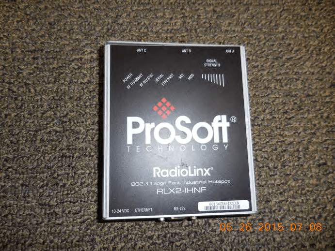
OQ7SR71A
Nov 03, 2015RLX2-IHNF, RLX2-IHN-W, RLX2-IHN-WC
Equipment Class
NII - Unlicensed National Information Infrastructure TX
OQ7IHW
Jan 28, 2008Mini PCI WLAN Transmitter Module
Equipment Class
DTS - Digital Transmission System
OQ7OS2401
Jun 18, 2003Locus 802.11b MiniPCI Radio Module with Amplifier
Equipment Class
DSS - Part 15 Spread Spectrum Transmitter
OQ7OS2400
Feb 17, 2000Spread Spectrum Transmitter MODULE
Equipment Class
DSS - Part 15 Spread Spectrum Transmitter