OQ7OS2401Locus 802.11b MiniPCI Radio Module with Amplifier
ProSoft Technology, Inc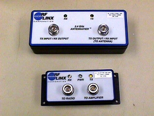
Click to zoom
Application Details
- Equipment Class
- DSS - Part 15 Spread Spectrum Transmitter
- Date of Grant
- Jun 18, 2003
- Application Purpose
- Original Equipment
- Date of Application
- Jun 18, 2003
- Equipment Note
- Locus 802.11b MiniPCI Radio Module with Amplifier
- Frequency Range
- 2400.00000000 - 2483.50000000
- Company
- ProSoft Technology, Inc
- Country
- United States
Documents & Files
Document Text
Text extracted from the exhibit documents filed with the FCC. Open a document above to read the original.
Users Manual
Locus OS2401 802.11b MiniPCI Radio Module with Amplifier User’s Guide June 17, 2003 Page 2 of 11 6/17/2003 REGULATORY APPROVALS United States FCC & Industry Canada rules Compliance Statement The following statements must be included in the product documentation for the end device in which the radio module is embedded: This device complies with Part 15 of the FCC Rules. Operation is subject to the following two conditions: (1) this device may not cause harmful interference, and (2) this device must accept any interference received, including interference that may cause undesired operation. NOTE: This equipment has been tested and found to comply with the limits for a Class A digital device, pursuant to Part 15 of the FCC Rules. These limits are designed to provide reasonable protection against harmful interference when the equipment is operated in a commercial environment. This equipment generates, uses, and can radiate radio frequency energy and, if not installed and used in accordance with the instruction manual, may cause harmful interference to radio communications. Operation of this equipment in a residential area is likely to cause harmful interference in which case the user will be required to correct the interference at his own expense. Product Labeling This radio module is labeled with an FCC ID number and a Canadian Certification Number. If this label is not visible when installed in an end-device, the outside of the device MUST also display a label referring to the enclosed OS2401. Use wording on the label similar to the following: "Transmitter Module FCC ID: OQ7OS2401, Canada 3656AOS2401". OR "This device contains Transmitter Module FCC ID: OQ7OS2401, Canada 3656AOS2401" CAUTION: Changes or modifications to this radio module not expressly approved by its manufacturer, Locus, Inc., may void the user’s authority to operate the equipment. NOTES: • Only approved antennas and power amplifier listed in this manual may be used with the OS2401. • The OS2400 Radio Module does not need to be re-authorized for compliance with Part 15,C intentional radiation (15.247 spread spectrum rules) or Part 15, B unintentional radiation. However, if the device into which the module is inserted contains any frequency sources (oscillator, clocks, etc.) it will have to be verified according to Part 15, B unintentional radiation to make sure that it does not unintentionally radiate. Page 3 of 11 6/17/2003 Antenna spacing requirements for user safety It is important to keep the radio’s antenna a safe distance from the user. To meet the requirements of FCC part 2.1091 for radio frequency radiation exposure, this radio must be used in such a way as to guarantee at least 20 cm between the antenna and users. Greater distances are required for high-gain antennas; for more details, see the Choosing the Antennas section. The FCC requires a minimum distance of 1 mW *cm 2 power density from the user (or 20 cm, whichever is greater). The installer of this radio equipment must ensure that the antenna is located or pointed such that it does not emit RF fields in excess of Health Canada limits for the general population; consult Safety Code 6, obtainable from Health Canada. To reduce potential radio interference to other users, the antenna type and its gain should be so chosen that the equivalent isotropically radiated power (EIRP) is not more than that required for successful communication. Copyright Copyright 2003 Locus Inc. All rights reserved. Locus has taken care to ensure the accuracy of this document. However, Locus assumes no liability for errors or omissions, and reserves the right to make changes without further notice to any products herein to improve reliability, function, or design. Locus provides this document without warranty of any kind, either implied or expressed, including, but not limited to, the implied warranties of merchantability and fitness for a particular purpose. Locus may make improvements or changes in the product(s) and/or program(s) described in this document at any time. This document contains proprietary information that is protected by copyright. No part of this document may be photocopied, reproduced, or translated to another language without written permission from Locus. Additionally, no part of electronic versions of this document may be deleted, changed, added to, or copied without written permission from Locus. Locus assumes no liability for use of this document if the content or format has been altered in any way. Locus reserves the right to revise this publication and to make changes in content from time to time without obligation on the part of Locus to provide notification of such revision or change. Page 4 of 11 6/17/2003 Table of Contents REGULATORY APPROVALS................................................................................................................................2 UNITED STATES FCC & INDUSTRY CANADA RULES.................................................................................................2 Compliance Statement..........................................................................................................................................2 Product Labeling..................................................................................................................................................2 ANTENNA SPACING REQUIREMENTS FOR USER SAFETY..............................................................................................3 COPYRIGHT...............................................................................................................................................................3 PRODUCT OVERVIEW...........................................................................................................................................5 MODULE INTEGRATION.......................................................................................................................................5 MODULE PHYSICAL DI…
Text truncated - open the document above for the full version.
Attestation Statements
Locus, Incorporated • 5540 Research Park Drive • Fitchburg Center • Madison, Wisconsin 53711 • USA Phone: 608/270-0500 • Fax: 608/270-5257 • www.locusinc.com Federal Communications Commission 445 12th Street SW Washington, DC 20554 Re: Modular Approval Request Letter for FCC ID: OQ7OS2401 To Whom It May Concern: In regard to the submission for equipment authorization of the Locus, Inc. OQ7OS2401, Locus, Inc. hereby respectfully requests authorization for modular approval. The radio is a MiniPCI 802.11b WLAN module. Locus, Inc. requests the modular approval so that Locus may enclose the module in Access Points customized for OEM partners without re-authorization of the module. The requirements of Public Notice DA00-1407 have been met and shown in the following statements. 1. “The modular transmitter must have its own RF shielding.” The RF portion of the unit has been shielded separately. See attached photos. 2. “The modular transmitter must have buffered modulation / data inputs (if such inputs are provided) to ensure that the module will comply with Part 15 requirements under conditions of excessive data rates or over-modulation.” The module has buffered data input through the ISL3874 MiniPCI interface. The transmitted data rate and modulation methods are in accordance with the specifications of the IEEE 802.11b standard. 3. “The modular transmitter must have its own power supply regulation.” The module contains a regulator on the DC input port. The part number is AME8801BEEV. 4. “The modular transmitter must comply with the antenna requirements of the section 15.203 and 15.204(C).” In order to ensure that no antennas other than those furnished by Locus, Inc are used, the module uses a unique U.FL series connector from Hirose. In addition, the antennas approved use unique connects of type reverse polarity SMA and reverse polarity N. Cables supplied by Locus will be used to connect the module to the antennas. These connectors meet the requirements as specified in Public Notice DA00-2225. The antennas that Locus will allow for installation are contained in the User Manual and have been tested for the authorization. 5. “The modular transmitter must be tested in a stand-alone configuration.” The module has been tested in a stand-alone configuration as shown in the photos. The module has been connected to an Access Point in order to provide data to it for testing. However, no additional shielding has been provided by this configuration. This is a representative configuration. 6. “The modular transmitter must be labeled with its own FCC ID number.” Please see the exhibit FCC Label for the FCC ID label of this module. The end product will contain the wording, “This device contains a transmitter module FCC ID: OQ7OS2401 as described in the User’s Manual. 7. “The modular transmitter must comply with any specific rule or operating requirements applicable to the transmitter and the manufacturer must provide adequate instructions along with the module to explain any such requirements.” The module complies fully with the requirements for 15.247. No additional requirements need to be met by the end user to ensure its compliance with 15.247. 8. “The modular transmitter must comply with any applicable RF exposure requirements.” The module complies with all RF exposure requirements. The details are addressed in the RF Exposure section. Thank you for your consideration. If you have any questions, please contact me. Regards, James A. Weikert Project Engineer Locus Incorporated
External Photos
FCC ID: OQ7OS2401 June 2003 Page 76 of 82 EXHIBIT III EXTERNAL PHOTOS FCC ID: OQ7OS2401 June 2003 Page 77 of 82
ID Label/Location Info
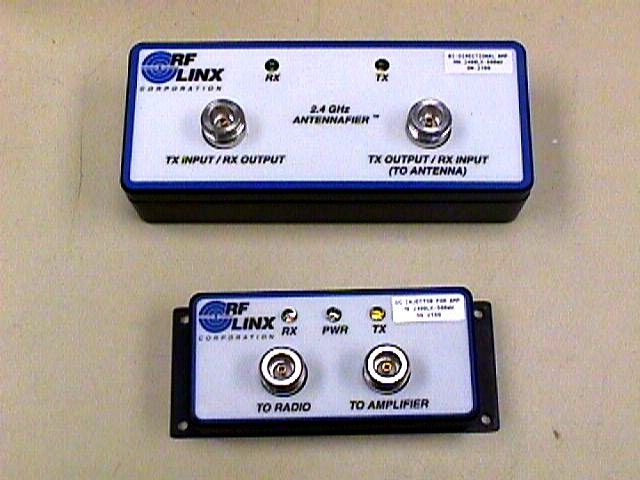
DC Injector Label and Location Power Amplifier Label and Location
Internal Photos
FCC ID: OQ7OS2401 June 2003 Page 78 of 82 EXHIBIT IV INTERNAL PHOTOS FCC ID: OQ7OS2401 June 2003 Page 79 of 82 FCC ID: OQ7OS2401 June 2003 Page 80 of 82
Operational Description
Approved Antennas Antennas approved for use without Bi-Directional Amplifier When the module is connected directly to an antenna, the following antennas may be used. Type Pattern Manufacturer Manufacturer’s Part Number Gain Connector Locus PN 1/2 Wave Omni NCC N2400SM9B 2dB SMA-RP 540-0003 1/2 Wave art. Omni Nearson S181AH-2450S 2dB SMA-RP 540-0002 Collinear Array Omni Antenex TRA24003NP 3dB SMA-RP 540-0036 Collinear Array,art. Omni Nearson S151AH-2450S 5dB SMA-RP 540-0005 Collinear Array Omni Maxrad MFB-24008RPN 8dB N-RP 540-0006 Collinear Array Omni Mobile Mark OD9-2400 9dB N-RP 540-0037 Collinear Array Omni Mobile Mark OD12-2400 12dB N-RP 540-0038 Patch Directional Arc Wireless AAI-000-89 8dB SMA-RP 540-0010 Patch Directional Maxrad MP24011PTRPMSMA 11dB SMA-RP 540-0011 Patch Directional Arc Wireless AAI-000-79 13dB N-RP 540-0034 Patch * Directional Arc Wireless AAI-000-84 19dB N-RP 540-0035 Yagi Directional Maxrad MYP24013PTRPNF 13dB N-RP 540-0009 Parabolic * Directional Pacific Wireless PMANT15-HD-PF1 RPN 15 dB N-RP 540-0017 Parabolic * Directional Pacific Wireless PMANT19-HD-PF1 RPN 19 dB N-RP 540-0018 Parabolic * Directional Pacific Wireless PMANT25 RPN 24 dB N-RP 540-0008 Antennas for use with Amplifier When the module is used in conjunction with the Amplifier, the antennas are limited to those below. Type Pattern Manufacturer Manufacturer’s Part Number Gain Connector Locus PN 1/2 Wave Omni NCC N2400SM9B 2dB SMA-RP 540-0003 1/2 Wave art. Omni Nearson S181AH-2450S 2dB SMA-RP 540-0002 Collinear Array Omni Antenex TRA24003NP 3dB SMA-RP 540-0036 Collinear Array,art. Omni Nearson S151AH-2450S 5dB SMA-RP 540-0005 Collinear Array Omni Maxrad MFB-24008RPN 8dB N-RP 540-0006 Collinear Array Omni Mobile Mark OD9-2400 9dB N-RP 540-0037 Collinear Array Omni Mobile Mark OD12-2400 12dB N-RP 540-0038 Patch Directional Arc Wireless AAI-000-89 8dB SMA-RP 540-0010 Patch Directional Maxrad MP24011PTRPMSMA 11dB SMA-RP 540-0011 Patch Directional Arc Wireless AAI-000-79 13dB N-RP 540-0034 Yagi Directional Maxrad MYP24013PTRPNF 13dB N-RP 540-0009 Note: To prevent high gain antennas from being used with an amplifier, Parabolic antennas will not be sold if the user is ordering an amplifier. 4 See http://www.antenex.com for product additions and more product detailsSee http://www.antenex.com for product additions and more product details Custom Tuning Available on Phantom ® models for only $10.00 US Patent Number: 5,977,931 CENTER: 915.000 MHz SPAN: 50.000 MHz CH1 RFL SWR 250 m / REF 1.5 2.0 1.5 1.0 Cor 2 1 3 1: 1.0163 915.000 MHz 3: 2.0000 927.626 MHz 2: 1.9174 902.000 MHz TRA9023N 2.0 1.5 1.0 250 m / REF 1.5 CH1 RFL SWR SPAN: 100.000 MHz CENTER: 835.000 MHz 1: 1.1899 835.000 MHz 3: 1.6339 869.000 MHz 2: 1.8242 806.000 MHz Cor 2 1 3 TRA8063 VSWR TRA4503 1.5 1.0 250 m / REF 1.5 CH1 RFL SWR SPAN: 100.000 MHz CENTER: 460.000 MHz 2: 1.0867 460.000 MHz 3: 1.6306 470.000 MHz 1: 1.5825 450.000 MHz Cor 1 2 3 2.0 TRAT1500 CENTER: 162.000 MHz SPAN: 5.000 MHz CH1 RFL SWR 250 m / REF 1.5 1.5 1.0 Cor 2 3 2.0 1: 1.1562 162.000 MHz 3: 1.3948 162.500 MHz 2: 1.5624 161.500 MHz 1 The ® Phantom ® Antennas are Ideal for Vending, Data, Mobile Transit, and PCS Applications. Wireless Data Collection PCS TRAB4503 TRA4503P Permanent Mount TRA8063 Ordering Guide - Clear, Easy & Sensible! TRA9023 = Phantom ® Antenna Model, White, 902-928 MHz, 3 dB-MEG. TRA Antenna Style Phantom ® Low-Profi le Transit Antenna Blank Finish Blank = White B = Black 902 Frequency Frequency component of part number in bold below: 142-164 150-174 210-230 410-425 430-450 450-470 470-490 806-866 821-896 890-960 902-928 2400-2500 3 Gain 0 = Unity 3 = 3 dB-MEG Blank Mount Blank = Normal Model N = No Ground Plane Model Blank Mount Option Blank = 3/4” Screw Base P = Permanent Hole Mount TRAB8063 TRA4503 Vending Product Courtesy of Gastronics, Inc. Indoor Enhancement Phantom ® Antennas Patented Whipless Performance WHITE MODELS Frequency Radome Model Range Height Gain MSRP VHF UNITY MODELS TRAT1420 142-160 MHz 3.30” Unity 72.00 TRAT1500 150-168 MHz 3.30” Unity 72.00 TRAT1560 162-172 MHz 3.30” Unity 72.00 TRA2100 210-225 MHz 3.30” Unity 72.00 UHF 3 dB-MEG MODELS TRA4103 410-425 MHz 3.30” 3 dB-MEG* 41.08 TRA4303 430-450 MHz 3.30” 3 dB-MEG* 41.08 TRA4503 450-470 MHz 3.30” 3 dB-MEG* 41.08 TRA4703 470-490 MHz 3.30” 3 dB-MEG* 41.08 800 MHz to 2.4 GHz 3 dB-MEG MODELS TRA8063 806-866 MHz 2.30” 3 dB-MEG* 38.70 TRA8213 821-896 MHz 2.30” 3 dB-MEG* 38.70 TRA8903 890-960 MHz 2.30” 3 dB-MEG* 38.70 TRA9023 902-928 MHz 2.30” 3 dB-MEG* 38.70 TRA24003 2400-2500 MHz 2.30” 3 dB-MEG* 38.70 900 MHz to 2.4 GHz NGP 3 dB-MEG MODELS TRA9023N 902-928 MHz 3.30” 3 dB-MEG* 41.08 TRA24003N 2400-2500 MHz 3.30” 3 dB-MEG* 41.08 UHF PERMANENT 3 dB-MEG MODELS TRA4303P 430-450 MHz 3.30” 3 dB-MEG* 65.13 TRA4503P 450-470 MHz 3.30” 3 dB-MEG* 65.13 TRA4703P 470-490 MHz 3.30” 3 dB-MEG* 65.13 800 MHz to 2.4 GHz PERMANENT 3 dB-MEG MODELS TRA8063P 806-866 MHz 2.30” 3 dB-MEG* 65.13 TRA8213P 821-896 MHz 2.30” 3 dB-MEG* 65.13 TRA24003P 2400-2500 MHz 2.30” 3 dB-MEG* 65.13 800 MHz to 2.4 GHz PERMANENT NGP 3 dB-MEG MODELS TRA8213NP 821-896 MHz 2.30” 3 dB-MEG* 65.13 TRA8903NP 890-960 MHz 2.30” 3 dB-MEG* 65.13 TRA9023NP 902-928 MHz 2.30” 3 dB-MEG* 65.13 TRA24003NP 2400-2500 MHz 2.30” 3 dB-MEG* 65.13 Our unique patented Phantom ® is a tough antenna for outdoor or indoor applications. The Phantom ® revolutionary design features fi eld diversity with both vertical and horizontal polarization components. This gives the antenna diversity, frequency agility, low visibility, wide bandwidth and a low angle radiation pattern that is superior to traditional gain antennas in most applications. The industry standard NMO mounting socket mates with all ® Magnetic, Trunk lid, and hole mounts. We also provide a threaded stud mount model for vandal resistant mounting on brackets, panels, ceilings or any other kind of housing. The Phantom ® patented technology is benefi cial when high performance is desired and extreme ruggedness an…
Text truncated - open the document above for the full version.
RF Exposure Info
RF Exposure Calculations From FCC 1.1310 table 1A, the maximum permissible RF exposure for an uncontrolled environment is 1mW/(cm 2 ). The electric field required to generate power density exposure (S) of 1mW/(cm 2 ) is calculated as follows: S E 2 Z := where S is Power Density (W/m 2 ), E is electric field (V/m) and Z is the impedance of free space (377Ω). Thus the Electric Field allowable (E a ) to limit Power Density to 1mW/(cm 2 ), given that 1mW/(cm 2 ) is equivalent to 10W/m 2 , is given by: E a SZ ⋅ := E a 10 W m 2 ⋅ 377 ⋅Ω⋅:= E a 61.4 V m = Maximum conducted peak output power (P out ) from the OQ7OS2401 radio module without the amplifier is 16.1dBm. Given an antenna gain (G ant ) of 24dB, the maximum effective isotropic radiated power (EIRP) is 10.2W as shown below. P rad 10 P out G ant + 10 mW ⋅:= P rad 10.2W = Since power density S (W/m 2 ) is related to effective radiated power P (watts) by the following equation, S P 4 π⋅ D 2 ⋅ := and using the relationship between S and E above, the following equation can be derived for the minimum safe separation distance to ensure exposure limits below 1mW/cm 2 . D min P rad 377 Ω⋅ 4 π⋅ ⋅ E a := D min 28.5cm = Repeating the calculations with the amplifier, the maximum output power of 19.5dBm and maximum antenna gain of 13dB result in a minimum safe separation distance of 11.9cm.
Test Report
Locus Inc. Application For Certification Locus 802.11b MiniPCI Radio Module with 2400LX-500mW Bi-Directional Amplifier FCC ID: OQ7OS2401 June 2003 All services undertaken are subject to the following general policy: Reports are submitted for exclusive use of the client to whom they are addressed. Their significance is subject to the adequacy and representative character of the samples and to the comprehensiveness of the tests, examinations or surveys made. No quotations from reports or use of Intertek Testing Services name is permitted except as expressly authorized by Intertek Testing Services in writing. The report must not be used by the client to claim product endorsement by NVLAP or any agency of the U.S. Government. The NVLAP logo is applicable for testing to I EC/CISPR 22:1993 and FCC-47 CFR part 15 only. Intertek 7250 Hudson Boulevard, Suite 100, Oakdale, MN 51228 Telephone 651-730-1188, Fax 651-730-1282 Home Page www.etlsemko.com TABLE OF CONTENTS 1.0 General Description..........................................................................................1 1.1 Related Submittal(s) Grants............................................................................1 1.2 Product Description......................................................................................1 1.3 Test Methodology........................................................................................3 1.4 Test Facility...............................................................................................3 2.0 System Test Configuration.................................................................................4 2.1 Justification...............................................................................................4 2.2 EUT Exercising Software...............................................................................4 2.3 Special Accessories......................................................................................4 2.4 Equipment Modification................................................................................4 2.5 Support Equipment List and Description.............................................................4 2.6 Test Configuration Block Diagram....................................................................5 3.0 Test Results.....................................................................................................7 3.1 Maximum Peak Output Power.........................................................................8 3.1.1 Antennas Compliance with Output Power...............................................15 3.2 6dB Bandwidth..........................................................................................16 3.3 Band Edge Compliance.................................................................................23 3.4 Spurious Emissions 20dB Attenuation...............................................................36 3.5 Peak Power Spectral Density..........................................................................45 3.6 Spurious Radiated Emissions..........................................................................52 3.7 Conducted Emissions...................................................................................61 3.8 Field Strength Calculation.............................................................................66 4.0 Test Equipment...............................................................................................67 EXHIBIT I Test Set Up Photographs......................................................................................68 EXHIBIT II FCC ID Label Location........................................................................................75 EXHIBIT III External Photographs..........................................................................................76 EXHIBIT IV Internal Photographs...........................................................................................78 EXHIBIT V Electrical Schematics and Block Diagram..................................................................81 EXHIBIT VI User Manual and Operational Description.................................................................82 FCC ID: OQ7OS2401 June 2003 Page 1 of 82 1.0 GENERAL DESCRIPTION 1.1 Related Submittals Grants This is single application of the Locus 802.11b MiniPCI Radio Module with Bi-Directional Amplifier Model: 2400LX-500mW for Certification under FCC Part 15, Subpart C. There are no other simultaneous applications. The Receiver portion will be verified under Declaration of Conformity. 1.2 Product Description The Locus 802.11b MiniPCI Radio Module (Further: MiniPCI Radio) is an industrial radio provides a wireless Ethernet communication. The MiniPCI Radio is a Digitally Modulated Intentional Radiator operating at 11 channels within 2400 - 2483.5MHz frequency band under CFR 47:2002, Section 15.247. The intended use of the MiniPCI Radio unit is to generate a RF signal, deliver the signal directly or through external amplifier to the antenna in order to communicate with the remote OS2400 series radios. The system includes MiniPCI Radio and Bi-Directional Amplifier Model # 2400LX-500mW with DC Injector manufactured by RF Linx Corp. The MiniPCI Radio is connected to the computer via Ethernet, or Serial cable; the MiniPCI Radio RF Output port connected to DC Injector input port and DC Injector output port connected to the RF Input port of the Amplifier, and the antenna connected to the RF Output port of the Amplifier; both MiniPCI Radio and DC Injector are powered at 120VAC/60Hz through Power Adapters. The MiniPCI Radio could operate without Amplifier. In order to demonstrate compliance with FCC regulations the MiniPCI Radio has been tested stand alone and with Amplifier. FCC ID: OQ7OS2401 June 2003 Page 2 of 82 Antennas: Five Antennas have been tested with MiniPCI Radio (without Amplifier) in order to demonstrate compliance with FCC requirements. Measurements were perfo…
Text truncated - open the document above for the full version.
Test Setup Photos
FCC ID: OQ7OS2401 June 2003 Page 68 of 82 EXHIBIT I TEST SET UP PHOTOS FCC ID: OQ7OS2401 June 2003 Page 69 of 82 FCC ID: OQ7OS2401 June 2003 Page 70 of 82 FCC ID: OQ7OS2401 June 2003 Page 71 of 82 FCC ID: OQ7OS2401 June 2003 Page 72 of 82 FCC ID: OQ7OS2401 June 2003 Page 73 of 82 FCC ID: OQ7OS2401 June 2003 Page 74 of 82
Contact Information
Applicant
Frank Hardy(Compliance Engineer)
Technical Contact
Locus, Inc.Gary Enstad
[email protected]608-270-0500
5440 Research Park Drive · Madison, Wisconsin · United States
Non-Technical Contact
Locus, Inc.Gary Enstad
[email protected](608)270-0500
Test Firm
Intertek Testing ServicesUri Spector
Technical Specifications
| # | Rule Parts | Frequency Range | Power Output |
|---|---|---|---|
| 1 | 15C | 2.40 GHz - 2.48 GHz | 425.00 mW |
Other Applications from ProSoft Technology, Inc
OQ7SR71A
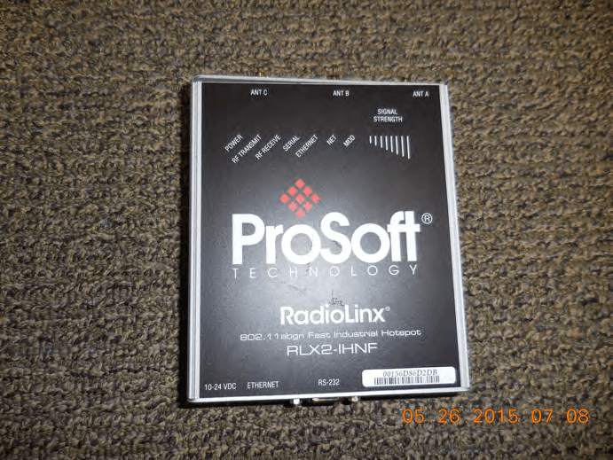
Nov 03, 2015RLX2-IHNF, RLX2-IHN-W, RLX2-IHN-WC
Equipment Class
NII - Unlicensed National Information Infrastructure TX
OQ7-IHN
Nov 14, 2011RLXIB-IHN, RLXIB-IHN-W, RLXIB-IHN-WC, RLXIB-IH2N, RLXIB-IH2N-W, & RLXIB-ICN
Equipment Class
DTS - Digital Transmission System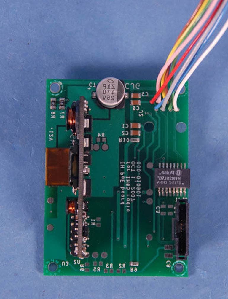
OQ7IHW
Jan 28, 2008Mini PCI WLAN Transmitter Module
Equipment Class
DTS - Digital Transmission System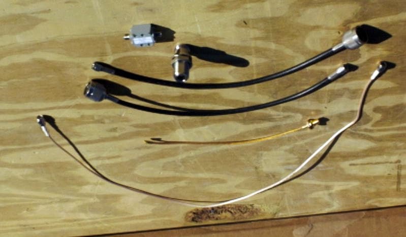
OQ7OS2400
Feb 17, 2000Spread Spectrum Transmitter MODULE
Equipment Class
DSS - Part 15 Spread Spectrum Transmitter