OQH-000000-10-001Wireless Weather Station
Chung's Electronic Co. Ltd.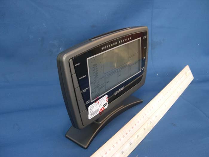
Click to zoom
Application Details
- Equipment Class
- CYY - Communications Receiver used w/Pt 15 Transmitter
- Date of Grant
- Aug 29, 2010
- Application Purpose
- Original Equipment
- Date of Application
- Aug 29, 2010
- Equipment Note
- Wireless Weather Station
- Frequency Range
- 915.00000000 - 915.00000000
- Company
- Chung's Electronic Co. Ltd.
- Country
- Hong Kong
Documents & Files
Document Text
Text extracted from the exhibit documents filed with the FCC. Open a document above to read the original.
Users Manual
C8249E-PD10122M (WWVB) Size:105 x 130 (mm) RADIO CONTROLLED WIRELESS WEATHER STATION Instruction Manual & Warranty FCC Remarks This device complies with Part 15 of the FCC Rules. Operation is subject to the following two conditions: (1) This device may not cause harmful interference, and (2) This device must accept any interference received, including interference that may cause undesired operation. Warning: Changes or modifications to this unit not expressly approved by the party responsible for compliance could void the user’s authority to operate the equipment. NOTE: This equipment has been tested and found to comply with the limits for a Class B digital device, pursuant to Part 15 of the FCC Rules. These limits are designed to provide reasonable protection against harmful interference in a residential installation. This equipment generates, uses and can radiate radio frequency energy and, if not installed and used in accordance with the instructions, may cause harmful interference to radio communications. However, there is no guarantee that int erference will not occur in a particular installation. If this equipment does cause harmful interference to radio or television reception, which can be determined by turning the equipment off and on, the user is encouraged to try to correct the int erference by one or more of the following measures: Reorient or relocate the receiving antenna. Increase the separation between the equipment and receiver. Connect the equipment into an outlet on a circuit different from that to which the receiver is connected. Consult the dealer or an experienced radio/TV technician for help. Model SPC502 USD $9.00 1 20 Thank you for your purchase of this delicate clock. The utmost care has gone into the design and manufacture of your clock. Please read these instructions car ef ully and keep them well for future reference. The multifunctional weather station is equipped with many functions providing thorough weather information to you. The receiver unit has a clear, easy-to-read display that shows the weather forecast, indoor temperature & humidity, moon phase, time, month, date as well as the temperature & humidity measured and transmitted from the remote sensor. The 915 MHz technology means no wire installation is required and you can place the sensor anywhere you like With radio controlled function, the current time and date are automatically synchronized with the time signal transmitted from U.S.A (WWVB). REMOTE SENSOR Recommended operating range: Resolution: Humidity measuring range: Operating range: Resolution: RF transmission frequency: Remote sensor: RF transmission range: Temperature sensing cycle: POWER Main unit: Remote sensor: DIMENSION Main unit: Remote sensor: -20°C to 55°C -4°F to 131°F 0.1°C/1°F(above 0°C/32°F) 1°C/1°F(below 0°C/32°F) 20%RH to 90%RH 20%RH to 90%RH 1%RH 915MHz 1 unit maximum 100 meters around 60-64 seconds 4.5V, use 3 x AA 1.5V alkaline battery 3V, use 2 x AA 1.5V alkaline battery 253(W) x 181(H) x 71(D)mm 40(W) x 132 (H) x 24 (D)mm TABLE OF CONTENCE Pg1 - Pg6------ Weather Station Main Features Pg6 - Pg7------ Setting Up the Transmitter Pg8 - Pg9------ Setting Up the Weather Station Pg10 - Pg11-- Manually Setting the Time and Calendar Pg11 - Pg12-- Setting the Alarm and Snooze Pg12 - Pg17-- Weather Forecast Features Pg17------------ Low Battery Indicator Pg18------------ Transmitter Wall Mounting Pg19 - Pg20-- Weather Station Specifications within 100 meters. 2 19 MAIN FEATURES: WEATHER STATION: 14 15 16 17 18 19 RESET 11 10 12 13 1 2 3 4 5 6 7 8 9 14 15 16 17 18 SPECIFICATION MAIN UNIT Recommended operating range: Resolution: Humidity measuring range: Recommended operating range: Resolution: Pressure measuring range: Pressure sampling cycle: Moon phase scanner range: Radio controlled signal: 0°C to 45°C 32°F to 113°F 1°C/°F(above 0°C/32°F) 1°C/°F(below 0°C/32°F) 20%RH to 90%RH 20%RH to 90%RH 1%RH1%RH 850mb to 1050mb 15 minutes from year 2000 to 2099 WWVB RESET 318 1.MODE key: •Press it to switch between alarm1 and alarm2. •Press and hold it for 2 second to enter normal time setting. •In normal time setting, press it to step the setting items. 2.HISTORY key: •Press it to check the pressure records in the past 24 hours. 3.mb-hPa/inHg key: •Press it to switch between mb-hPa and inHg. •Press and hold it for 2 seconds to enter the “rel” and “abs” switch mode. 4.MAX/MIN key: •Press it to check the maximum/minimum temperature & humidity records. •Press and hold it for 3 seconds to delete the maximum and minimum records. 5.ALM key: •In normal mode, press it to turn on/off alarm1 and alarm2. •In alarm1/alarn2 mode, press and hold it for 2 seconds to enter alarm time setting. •In alarm setting mode, press it to step the setting items. 6.°C/°F key: •Press it to switch between Celsius and Fahrenheit. NOTE: Attention! Please dispose of used unit or batteries in an ecologically safe manner. USING THE TABLE STAND OR WALL-MOUNTING STAND The receiver and transmitter have both the desktop and wall-mounting structures. For the receiver, place the screw on the desired wall and hang the receiver by the recessed hole at the back of the clock or just simply place it on the desktop by the table stand. For the transmitter, fix the separate wall-mounting stand outside in the area protected from direct rain by the screw. Once the stand is mounted, place the transmitter into the stand on the wall. Besides, you can place it on the desktop by its table stand. 417 •Press and hold it for 3 seconds to receive the RC signal for reception testing. 7.UP key: •In setting mode, press it to increase the setting value. •Press it to select the channel 1, 2 or 3. 8.DOWN key: •In setting mode, press it to decrease the setting value. •In normal mode or alarm mode, press it switch between 12 and 24 hour format. 9.SNOOZE/LIGHT key: •Press it once to turn on the backlight for 5 seconds. •Press it to stop the current alarm when it is sounding and enter the snooze mode. 10.WALL-…
Text truncated - open the document above for the full version.
Block Diagram
CHUNG’S ELECTRONIC CO.,LTD. CHUNG’S EECTRONIC CO.,LTD Description name Block diagram Model C8249 File No FCC8249-BN Date 26-7-10 Name KHChan U1 TM8959 Radio controlled clock U6 915MHz RF227 FSK RF receiver LCD -902 P03 PRESSURE SENSOR 60 kHz Receiver U2 CME6005 60kHz Ferrite antenna 3.3V Regulator U8 Light Crystal 3.58MHz Crystal 32.768kHz Keyboard Crystal 10MHz 915MHz LOOP ANTENNA 4.5V Battery 3.6V Regulator U7 Buzzer RF Receiver RF227 Block Diagram
External Photos
INTERTEK TESTING SERVICE Report No.: HK10061385-1 Equipment Photographs Model : SPC502 (External) FCC ID: OQH-000000-10-001
Internal Photos
INTERTEK TESTING SERVICE Report No.: HK10061385-1 FCC ID: OQH-000000-10-001 Equipment Photographs Model : SPC502 (Internal) INTERTEK TESTING SERVICE Report No.: HK10061385-1 FCC ID: OQH-000000-10-001 Equipment Photographs Model : SPC502 (Internal) INTERTEK TESTING SERVICE Report No.: HK10061385-1 FCC ID: OQH-000000-10-001 Equipment Photographs Model : SPC502 (Internal) INTERTEK TESTING SERVICE Report No.: HK10061385-1 FCC ID: OQH-000000-10-001 Equipment Photographs Model : SPC502 (Internal) INTERTEK TESTING SERVICE Report No.: HK10061385-1 FCC ID: OQH-000000-10-001 Equipment Photographs Model : SPC502 (Internal)
Operational Description
C-8249 (915MHz FCC) TECHNICAL DESCRIPTION A. CIRCUIT DESCRIPTION 1. The equipment is wireless weather forecast station ,the outdoor data from 915MHz frequency FSK receiver ,reception cycle every 5 seconds in each channel and the 915MHz RF-IC is all programmable and no alignment required in production ,the receive frequency very stable . 2. The equipment power up full display then the micro controller setting RF IC and read the digital pressure sensor data and indoor temperature & humidity data ,during the power up after 8 seconds to 60 seconds is 915MHz RX test mode , after power up 68 seconds radio controlled receiver power on. B. MAIN COMPONENT DESCRIPTION SYMBOL COMPONENT NAME DESCRIPTION X4 10MHz Crystal Stable RF transmitter Oscillator frequency and other. X1 32.768kHz Crystal Provide reference clock 1 for MCU. X5 3.58MHz Crystal Provide reference clock 2 for MCU. X3 60.000kHz Crystal Radio controlled clock receiver crystal Buzzer Buzzer alarm sound output U1 TM8959 MCU (micro controller unit) Temperature and Humidity and air pressure and weather forecast icon and moon phase and air pressure bar calculate. Radio controlled clock and outdoor temperature and humidity data decoding . U2 CME6005 Radio controlled clock receiver Provide radio controlled clock data for micro controller unit P03 P03 Pressure sensor Provide air pressure data for MCU HH1 CL-HQM3R Humidity sensor Provide Humidity data for MCU TT1 RB103FS3435F 01 Temperature sensor Provide temperature data for MCU LCD902 LCD902 LCD Display in/out door temperature and clock . U6 RF 227 RF IC Receive outdoor 915MHz transmitter temperature U7 MD7336 Regulator Stable 3.6 voltage for RFIC operating U8 CS5333 Regulator Stable 3.3 voltage for MCU operating Loop antenna Loop antenna 915MHz band reception antenna L1 Ferrite antenna Ferrite antenna Radio control clock reception 60kHz ferrite antenna CHUNG’S ELECTRONIC CO.,LTD Name TECHNICAL DESCRIPTION Model C8249(FCC)915 File No RX8249(915) Date 26-7-10 Name Chan Kai Hung RF227 Universal ISM Band FSK Receiver RF227 DESCRIPTION: RF227 Hope’s RF227 is a single chip, low power, multi-channel FSK receiver designed for use in applications requiring FCC or ETSI conformance for unlicensed use in the 315, 433, 868, and 915 MHz bands. Used in conjunction with Hope's FSK transmitters, the RF227 is a flexible, low cost, and highly integrated solution that does not require production alignments. All required RF functions are integrated. Only an external crystal and bypass filtering are needed for operation. The RF227 has a completely integrated PLL for easy RF design, and its rapid settling time allows for fast frequency hopping, bypassing multi-path fading, and interference to achieve robust wireless links. The PLL’s high resolution allows the usage of multiple channels in any of the bands. The baseband bandwidth (BW) is programmable to accommodate various deviation, data rate, and crystal tolerance requirements. The receiver employs the Zero-IF approach with I/Q demodulation, therefore no external components (except crystal and decoupling) are needed in a typical application. The RF227 is a complete analog RF and baseband receiver including a multi-band PLL synthesizer with an LNA, I/Q down converter mixers, baseband filters and amplifiers, and I/Q demodulator. The chip dramatically reduces the load on the microcontroller with integrated digital data processing: data filtering, clock recovery, data pattern recognition and integrated FIFO. The automatic frequency control (AFC) feature allows using a low accuracy (low cost) crystal. To minimize the system cost, the chip can provide a clock signal for the microcontroller, avoiding the need for two crystals. For low power applications, the device supports low duty-cycle operation based on the internal wake-up timer. BLOCK DIAGRAM RF227 FEATURES: Fully integrated (low BOM, easy design-in) No alignment required in production Fast settling, programmable, high-resolution PLL Fast frequency hopping capability High bit rate (up to 115.2 kbps in digital mode and 256 kbps in analog mode) Direct differential antenna input Programmable baseband bandwidth (67 to 400 kHz) Analog and digital RSSI outputs Automatic frequency control (AFC) Data quality detection (DQD) Internal data filtering and clock recovery RX pattern recognition SPI compatible serial control interface Clock and reset signals for microcontroller 16 bit RX data FIFO Low power duty-cycle mode (less than 0.5 mA average supply current) Standard 10 MHz crystal reference Wake-up timer Low battery detector 2.2 to 5.4 V supply voltage Low power consumption (~9 mA in low bands) Low standby current (0.3 μA) TYPICAL APPLICATIONS Remote control Home security and alarm Wireless keyboard/mouse and other PC peripherals Toy control Remote keyless entry Tire pressure monitoring Te l e m e t r y Personal/patient data logging Remote automatic meter reading RF227 DETAILED DESCRIPTION General The RF227 FSK receiver is the counterpart of the Hope’s FSK transmitter. It covers the unlicensed frequency bands at 315, 433, 868, and 915 MHz. The device facilitates compliance with FCC and ETSI requirements. The programmable PLL synthesizer determines the operating frequency, while preserving accuracy based on the on-chip crystal-controlled reference oscillator. The PLL’s high resolution allows for the use of multiple channels in any of the bands. The receiver employs the Zero-IF approach with I/Q demodulation, allowing the use of a minimal number of external components in a typical application. The RF227 consists of a fully integrated multi-band PLL synthesizer, an LNA with switchable gain, I/Q down converter mixers, baseband filters and amplifiers, and an I/Q demodulator followed by a data filter. The RF VCO in the PLL performs automatic calibration, which requires only a few microseconds. Calibration always occurs when the synthesizer begins. If temperature or …
Text truncated - open the document above for the full version.
Schematics
C8249E-V04(fcc).sch-1 - Wed Aug 25 11:38:59 2010
Test Report
- The test report only allows to be revised within the retention period unless further standard or the requirement was noticed. - This report is for the exclusive use of Intertek's Client and is provided pursuant to the agreement between Intertek and its Client. Intertek's responsibility and liability are limited to the terms and conditions of the agreement. Intertek assumes no liability to any party, other than to the Client in accordance with the agreement, for any loss, expense or damage occasioned by the use of this report. Only the Client is authorized to permit copying or distribution of this report and then only in its entirety. Any use of the Intertek name or one of its marks for the sale or advertisement of the tested material, product or service must first be approved in writing by Intertek. The observations and test results in this report are relevant only to the sample tested. This report by itself does not imply that the material, product, or service is or has ever been under an Intertek certification program. Intertek Testing Services Hong Kong Ltd. 2/F., Garment Centre, 576 Castle Peak Road, Kowloon, Hong Kong. Tel: (852) 2173 8888 Fax: (852) 2785 5487 Website: www.hk.intertek-etlsemko.com TEST REPORT Report No.: HK10061385-1 Chung's Electronic Co., Ltd. Application For Certification (Original Grant) (FCC ID: OQH-000000-10-001) Superheterodyne Receiver Prepared and Checked by: Approved by: Signed On File Benny Lau Engineer Chan Chi Hung, Terry Senior Lead Engineer Date: August 26, 2010 INTERTEK TESTING SERVICES Report No.: HK10061385-1 FCC ID: OQH-000000-10-001 i GENERAL INFORMATION Chung's Electronic Co., Ltd. BRAND NAME: SHARP, MODEL: SPC502 FCC ID: OQH-000000-10-001 Grantee: Chung's Electronic Co., Ltd. Grantee Address: Unit 1-3, 9/F., Wang Lung Industrial Building, 11 Lung Tak Street, Tsuen Wan, N.T., Hong Kong. Contact Person: Mr. Joey Yip Tel: 852-2611 3000 Fax: 852-2611 3088 e-mail: [email protected] Manufacturer: N/A Manufacturer Address: N/A Brand Name: SHARP Model: SPC502 Type of EUT: Superheterodyne Receiver Description of EUT: Wireless Weather Station Serial Number: N/A FCC ID: OQH-000000-10-001 Date of Sample Submitted: June 28, 2010 Date of Test: June 30, 2010 Report No.: HK10061385-1 Report Date: August 26, 2010 Environmental Conidtions: Temperature: +10 to 40°C Humidity: 10 to 90% INTERTEK TESTING SERVICES Report No.: HK10061385-1 FCC ID: OQH-000000-10-001 ii SUMMARY OF TEST RESULT Chung's Electronic Co., Ltd. BRAND NAME: SHARP, MODEL: SPC502 FCC ID: OQH-000000-10-001 TEST SPECIFICATION REFERENCE RESULTS Maximum Peak Output Power 15.247(b), (c) / RSS-210 A8.4 N/A Hopping Channel Carrier Frequencies Separation 15.247(e) / RSS-210 A8.1 N/A 20dB Bandwidth of the Hopping Channel 15.247(a) / RSS-210 A8.1 N/A Number of Hopping Frequencies 15.247(e) / RSS-210 A8.1 N/A Average Time of Occupancy of Hopping Frequency 15.247(e) / RSS-210 A8.1 N/A Antenna Conducted Spurious Emissions 15.247(d) / RSS-210 A8.5 N/A Radiated Spurious Emissions 15.247(d) / RSS-210 A8.5 N/A RF Exposure Compliance 15.247(i) / RSS-Gen 5.5 N/A Transmitter Power Line Conducted Emissions 15.207 / RSS-Gen 7.2.2 N/A Transmitter Field Strength 15.227 / RSS-310 3.8 N/A Transmitter Field Strength 15.229 / RSS-210 A2.7 N/A Transmitter Field Strength, Bandwidth and Timing Requirement 15.231(a) / RSS-210 A1.1.1 N/A Transmitter Field Strength, Bandwidth and Timing Requirement 15.231(e) / RSS-210 A1.1.5 N/A Transmitter Field Strength and Bandwidth Requirement 15.239 / RSS-210 A2.8 N/A Transmitter Field Strength and Bandwidth Requirement 15.249 / RSS-210 A2.9 N/A Transmitter Field Strength and Bandwidth Requirement 15.235 / RSS-310 3.9 N/A Receiver / Digital Device Radiated Emissions 15.109 / ICES-003 Pass Digital Device Conducted Emissions 15.107 / ICES-003 N/A Note: 1. The EUT uses a permanently attached antenna which, in accordance to section 15.203, is considered sufficient to comply with the pervisions of this section. 2. Pursuant to FCC part 15 Section 15.215(c), the 20 dB bandwidth of the emission was contained within the frequency band designated (mentioned as above) which the EUT operated. The effects, if any, from frequency sweeping, frequency hopping, other modulation techniques and frequency stability over excepted variations in temperature and supply voltage were considered. INTERTEK TESTING SERVICES Report No.: HK10061385-1 FCC ID: OQH-000000-10-001 iii Table of Contents 1.0 General Description........................................................................................ 1 1.1 Product Description ........................................................................................... 1 1.2 Related Submittal(s) Grants............................................................................... 1 1.3 Test Methodology.............................................................................................. 1 1.4 Test Facility ....................................................................................................... 1 2.0 System Test Configuration ............................................................................. 2 2.1 Justification ....................................................................................................... 2 2.2 EUT Exercising Software................................................................................... 2 2.3 Special Accessories .......................................................................................... 2 2.4 Equipment Modification ..................................................................................... 2 2.5 Measurement Uncertainty.................................................................................. 2 2.6 Support Equipment List and Description ............................................................ 2 3.0 Emission Results ............................................................................................ 3 3.1 Field Strength Calculation.........................…
Text truncated - open the document above for the full version.
Test Setup Photos
INTERTEK TESTING SERVICE Report No: HK10061385-1 Configuration Photographs Worst-Case Radiated Emissions (Front View) Model : SPC502 Figure 1 FCC ID: OQH-000000-10-001 INTERTEK TESTING SERVICE Report No: HK10061385-1 Configuration Photographs Worst-Case Radiated Emissions (Back View) Model : SPC502 Figure 2 FCC ID: OQH-000000-10-001
Contact Information
Applicant
BILLY CHUNG(Managing Director)
Technical Contact
Intertek Testing Services Hong Kong LtdBen Ho
[email protected]2173 8505
2/F Garment Centre · Kowloon · Hong Kong
Non-Technical Contact
Intertek Testing Services Hong Kong LtdBen Ho
[email protected]2173 8505
Test Firm
Intertek Testing Services Hong Kong Ltd.Billy Chow
Technical Specifications
| # | Rule Parts | Frequency Range | Power Output |
|---|---|---|---|
| 1 | 15B | 915 MHz - 915 MHz | - |
Other Applications from Chung's Electronic Co. Ltd.
OQH-000000-15-001
Nov 22, 2015Wireless Rain Gauge
Equipment Class
DXX - Part 15 Low Power Communication Device Transmitter
OQH-000000-13-01
Apr 28, 2013Remote Senor
Equipment Class
DSC - Part 15 Security/Remote Control Transmitter
OQH-000000-06-007
Aug 26, 2006Wireless Weather Station (433.9MHz Tx)
Equipment Class
DSC - Part 15 Security/Remote Control Transmitter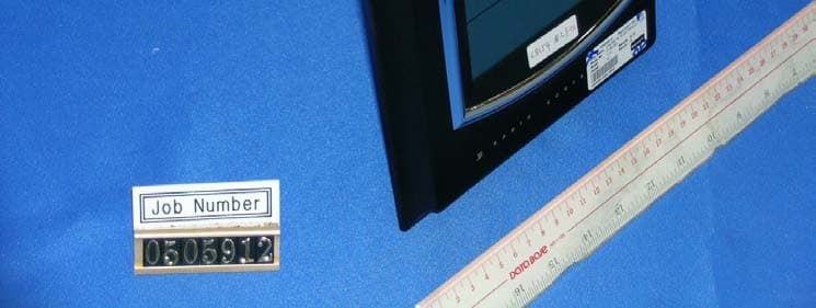
OQH-CHUNGS-05-004
Aug 29, 2005Wireless Weather Station (Receiver)
Equipment Class
CRR - Superregenerative Receiver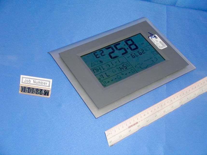
OQH-CHUNGS-05-003
Aug 29, 2005Wireless Weather Station (Receiver)
Equipment Class
CRR - Superregenerative Receiver