OQH-CHUNGS-05-004Wireless Weather Station (Receiver)
Chung's Electronic Co. Ltd.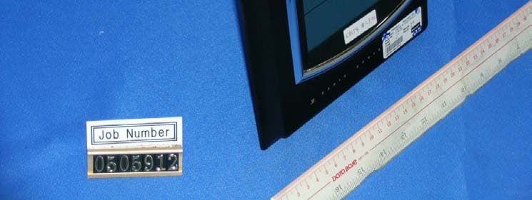
Click to zoom
Application Details
- Equipment Class
- CRR - Superregenerative Receiver
- Date of Grant
- Aug 29, 2005
- Application Purpose
- Original Equipment
- Date of Application
- Aug 29, 2005
- Equipment Note
- Wireless Weather Station (Receiver)
- Frequency Range
- 433.92000000 - 433.92000000
- Company
- Chung's Electronic Co. Ltd.
- Country
- Hong Kong
Documents & Files
Document Text
Text extracted from the exhibit documents filed with the FCC. Open a document above to read the original.
Users Manual
WIRELESS WEATHER STATION C-8154 USER’S INSTRUCTIONS P17815400030 1 p. 2 p. 25 p. The multifunctional weather station is equipped with many functions providing thorough weather information to you. The receiver unit has a clear, easy-to-read display that shows weather forecast, indoor temperature, pressure, moon phase, time and date, as well as the temperature measured and transmitted by the sensor. It is able to re- ceive and display readings from up to 3 remote sensors. The receiver unit retains the minimum and maximum temperatures and relative humidity readings measured at various locations. The 433 MHz technology means no wire installation is required and you can place the sensors anywhere you like. With radio controlled function, the current time and date are automatically synchronized with the time signal transmitted from Frankfurt Germany (DCF77) / UK (MSF) / US (WWVB). The signal can cover a distance of about 1500 km from the related transmitter. 24 p. 3 p. FCC Remarks: This device complies with Part 15 of the FCC Rules. Operation is subject to the following two conditions: (1) This device may not cause harmful interference, and (2) This device must accept any interference received, including interference that may cause undesired operation. Warning: Changes or modifications to this unit not expressly approved by the party responsible for compliance could void the user’s authority to operate the equipment. NOTE: This equipment has been tested and found to comply with the limits for a Class B digital device, pursuant to Part 15 of the FCC Rules. These limits are designed to provide reasonable protection against harmful interference in a residential installation. This equipment generates, uses and can radiate radio frequency energy and, if not installed and used in accordance with the instructions, may cause harmful interference to radio communications. However, there is no guarantee that interference will not occur in a particular installation. If this equipment does cause harmful interference to radio or television reception, which can be determined by turning the equipment off and on, the user is encouraged to try to correct the interference by one or more of the following measures: l Reorient or relocate the receiving antenna. l Increase the separation between the equipment and receiver. l Connect the equipment into an outlet on a circuit different from that to which the receiver is connected. lConsult the dealer or an experienced radio/TV technician for help. MAIN FEATURES: WEATHTER STATION: 1 23456 7 8 9 10 11 4 p. 23 p. Temperature resolution: 0.1 ºC / 1ºF (above 0 ºC) 1 ºC / ºF (below 0 ºC) RF transmission frequency:433MHz No of remote unit:up to 3 units RF transmission range:Maximum 30 meters Temperature sensing cycle:around 60 ~ 64 seconds Pressure measuring range:800mb to 1050mb Pressure sampling cycle:15 minutes Moon phase scanner range:From 2000 to 2050 Radio controlled signal:DCF77, MSF, WWVB Power: Main unit:4.5 V, use 3 x AA 1.5V alkaline battery Remote sensor:3 V, use 2 x AAA 1.5V alkaline battery Weight Main unit:650gm Remote sensor: 53gm Dimension Main unit: 306x224x24mm Remote sensor: 65(W)x93(H)x 27(D)mm 1. TIME: - Press it once to view the year. - Press and hold it for 2 seconds to enter the time setting mode. 2. ALARM: - Press it to switch to alarm and temperature alarm. - In alarm mode, press and hold it for 2 seconds to enter the alarm and pre-alarm setting mode. 3. UP: - In normal time mode, press it to choose between channel (1), (2) and (3). - In setting mode, press it to increase the setting value. - In alarm mode, press it to turn on/off alarm and snooze. 4. DOWN: - Press and hold it for 3 seconds, release, then press it to change the weather indicator. - In alarm mode, press it to turn on/off alarm and snooze. 5. HISTORY: - Check the past 24 hours pressure records. 6. MAX/MIN : - Press it once to check max./ min. temperature record. - Press and hold it for 3 seconds to delete the max. and min. record. 7. RESET: - Press it to set all values to factory value. 22 p. 5 p. Fix the separate wall-mounting stand on the wall by screws. Push the stand of the clock upward, hang it on the wall-mounting stand by its recessed holes. For the transmitter, fix the wall-mount holder on the wall or simply place it on the table. MAIN UNIT Indoor temperature measuring range: -5 ºC to +50 ºC Recommended operating range: 0 ºC to +45 ºC Temperature resolution: 0.1 ºC / 1ºF (above 0 ºC) 1 ºC / ºF (below 0 ºC) REMOTE SENSOR Temperature measuring range: -20 ºC to +60 ºC Recommended operating range: -20 ºC to +55 ºC - In case of mal-function, the unit may be required to reset. 8. ºC / ºF: - Switch between ºC / ºF. 9. mb/hPa . inHg: - Switch between mb/hPa or inHg. 10. TABLE STAND - use to stand on desktop 11. WALL-MOUNTING HOLE: - Use to support the main unit on wall. 12. WEATHER FORECAST WINDOW: SPECIFICATIONS - Displays the weather forecast indicator. 13. ATMOSPHERE PRESSURE WINDOW: - Displays the current atmospheric pressure data and indicates the last 24 hours pressure history. 14. CALENDAR WINDOW: - Displays the date, year, day of the week and moon phase. 15. CLOCK WINDOW: - Displays the time radio controlled signal. 6 p. 21 p. LOW BATTERY INDICATOR When the battery does not have enough power to operate the unit, the low battery indicator will appear to remind you to replace with new batteries. Transmitter’s low battery indicator Transmitter’s low battery indicator ( shows on transmitter ) ( shows on the main unit) Receiver’s low battery indicator NOTE: Attention should be drawn to the environmental aspects of battery disposal USING THE TABLE STAND OR WALL MOUNTING The receiver has both desk-top and wall-mounting structure. 16. INDOOR TEMPERATURE AND HUMIDITY WINDOW: - Shows the indoor temperature-trend, current temperature, or the maximum or minimum recorded temperature. 17. OUTDOOR TEMPERATURE : - Shows the outdoor temperature-trend, current temperature, or the maximum or mi…
Text truncated - open the document above for the full version.
Block Diagram
CHUNG’S ELECTRONIC CO.,LTD. CHUNG’S EECTRONIC CO.,LTD Description name Block diagram Model C8154 File No FCC8154-BN Date 1/4/05 Chan Kai Hung MCU1&2 Crystal 32k 433MHz RF receiver (super regeneration) LCD display Temperature sensor pressure sensor Figure 1 C-8154 Block diagram 60 kHz RCC Receiver Ferrite antenna Keyboard 3V Regulator 4.5V battery
External Photos
Test Setup FCC ID : OQH-CHUNGS-05-004 External Photo - Front External Photo - Rear
Internal Photos
Test Setup FCC ID : OQH-CHUNGS-05-004 Internal Photo - 1 Internal Photo - 2 Test Setup FCC ID : OQH-CHUNGS-05-004 Internal Photo - 3 Internal Photo - 4 Internal Photo - 5 Test Setup FCC ID : OQH-CHUNGS-05-004
Operational Description
C-8154 TECHNICAL DESCRIPTION A. CIRCIUT OPERATION 1. Temperature sensor. Provide temperature data for (MCU) micro controller unit. 2. Humidity sensor . Provide Humidity data for (MCU) micro controller unit. 3. Pressure sensor & A/D IC Provide air pressure data for A/D IC ,and then input MCU 1. 4. MCU1+MCU2 The micro controller unit (MCU) are encoding and manipulating temperature Humidity and pressure data and RC clock and 433 received and driver LCD. 5. RF Receiver Receive Convert RF modulated information into digital for (MCU). 6. Voltage regulator Stable RF receiver and (MCU) and (RC) Radio controlled receiver voltage . 7. LCD Display option Display indoor outdoor temperature and Humidity ,pressure ,pressure bar ,moon phase, time, date and other . B. COMPONENT DESCRIPTION CATEGOR Y NUMBER NAME DESCRIPTION Regulator 3A-0R 3V Regulator Stable RF receiver, RCC, pressure board and MCU Transistor 2SC1623 L6 Buzzer driver(Q1), black light(Q2) Transistor 2SC1623 L6 RF receiver switch (Q3) Transistor 2SA812 M6 RF receiver switch and reset circuit (Q4) Transistor H2D RF transistor 433.92MHz RF receiver IC SSC32210 Pressure A/D Pressure A/D MCU1 + MCU2 S1C63658 MSM64162A Micro controller unit decoding and manipulating temperature Humidity data from transmitter ,radio controlled ,pressure and drive LCD display . Crystal 32.768KHz 3*8 32k Quartz Stable MCU master clock Crystal 60KHz 2*6 60k Quartz For RCC receiver Display LCD379 C8154LCD Display time ,indoor outdoor temperature ,Humidity, 433 channel, alarm time, Pressure ,pressure bar ,weather and moon phase IC TL062CD SMD 062 433 MHz receiver Low pass amplifier and comparator IC UE6011 RCC receiver IC RCC receiver Transducer 8.5mm Transducer Alarm sound output Sensor 103AT Temperature sensor Provide temperature data for MCU Sensor DMP015A Pressure sensor Provide pressure data for MCU CHUNG’S ELECTRONIC CO.,LTD Name TECHNICAL DESCRIPTION Model C8154 File No FCC8154-T Date 1/4/05 Chan Kai Hung
Test Report
• The test results reported in this test report shall refer only to the sample actually tested and shall not refer or be deemed to refer to bulk from which such a sample may be said to have been obtained. • This report shall not be reproduced except in full without prior authorization from Intertek Testing Services Hong Kong Limited. • For Terms And Conditions of the services, it can be provided upon request. • The evaluation data of the report will be kept for 3 years from the date of issuance. Intertek Testing Services Hong Kong Ltd. 2/F., Garment Centre, 576 Castle Peak Road, Kowloon, Hong Kong. Tel: (852) 2173 8888 Fax: (852) 2371 0521 Website: www.hk.intertek-etlsemko.com Chung's Electronic Co., Ltd. Application For Certification (FCC ID: OQH-CHUNGS-05-004) Superregenerative Receiver 0505912 DL/ Sandy Lee June 13, 2005 INTERTEK TESTING SERVICES FCC ID: OQH-CHUNGS-05-004 i LIST OF EXHIBITS INTRODUCTION EXHIBIT 1: General Description EXHIBIT 2: System Test Configuration EXHIBIT 3: Emission Results EXHIBIT 4: Equipment Photographs EXHIBIT 5: Product Labelling EXHIBIT 6: Technical Specifications EXHIBIT 7: Instruction Manual EXHIBIT 8: Miscellaneous Information INTERTEK TESTING SERVICES FCC ID: OQH-CHUNGS-05-004 ii MEASUREMENT/TECHNICAL REPORT Chung's Electronic Co., Ltd. - MODEL: CHUNG'S C-8154 FCC ID: OQH-CHUNGS-05-004 This report concerns (check one:) Original Grant X Class II Change _____ Equipment Type: Superregenerative Receiver (example: computer, printer, modem, etc.) Deferred grant requested per 47 CFR 0.457(d)(1)(ii)? Yes No X If yes, defer until: date Company Name agrees to notify the Commission by: date of the intended date of announcement of the product so that the grant can be issued on that date. Transition Rules Request per 15.37? Yes No X If no, assumed Part 15, Subpart B for unintentional radiator - the new 47 CFR [12-08-03 Edition] provision. Report prepared by: Derek Leung Intertek Testing Services Hong Kong Ltd. 2/F., Garment Centre, 576, Castle Peak Road, Kowloon, Hong Kong. Phone: 852-2173-8539 Fax: 852-2371-0521 INTERTEK TESTING SERVICES FCC ID: OQH-CHUNGS-05-004 iii Table of Contents 1.0 General Description .......................................................................................... 2 1.1 Product Description ............................................................................................. 2 1.2 Related Submittal(s) Grants ................................................................................ 2 1.3 Test Methodology................................................................................................ 3 1.4 Test Facility ......................................................................................................... 3 2.0 System Test Configuration ............................................................................... 5 2.1 Justification ......................................................................................................... 5 2.2 EUT Exercising Software .................................................................................... 5 2.3 Special Accessories ............................................................................................ 5 2.4 Equipment Modification ....................................................................................... 6 2.5 Measurement Uncertainty ................................................................................... 6 2.6 Support Equipment List and Description ............................................................. 6 3.0 Emission Results .............................................................................................. 8 3.1 Field Strength Calculation ................................................................................... 9 3.2 Radiated Emission Configuration Photograph ................................................... 10 3.3 Radiated Emission Data.................................................................................... 11 4.0 Equipment Photographs ................................................................................. 14 5.0 Product Labelling ............................................................................................ 16 6.0 Technical Specifications ................................................................................ 18 7.0 Instruction Manual .......................................................................................... 20 8.0 Miscellaneous Information ............................................................................. 22 8.1 Stabilization Waveform...................................................................................... 23 8.2 Discussion of Pulse Desensitization .................................................................. 24 8.3 Calculation of Average Factor ........................................................................... 25 8.4 Emissions Test Procedures............................................................................... 26 INTERTEK TESTING SERVICES FCC ID: OQH-CHUNGS-05-004 iv List of attached file Exhibit type File Description filename Test Report Test Report report.pdf Operation Description Technical Description descri.pdf Test Setup Photo Radiated Emission radiated photos.doc External Photo External Photo external photos.doc Internal Photo Internal Photo internal photos.doc Block Diagram Block Diagram block.pdf Schematics Circuit Diagram circuit.pdf ID Label/Location Label Artwork and Location label.pdf User Manual User Manual manual.pdf Test Report Stabilization Waveform superreg.pdf INTERTEK TESTING SERVICES FCC ID: OQH-CHUNGS-05-004 1 EXHIBIT 1 GENERAL DESCRIPTION INTERTEK TESTING SERVICES FCC ID: OQH-CHUNGS-05-004 2 1.0 General Description 1.1 Product Description The Equipment Under Test (EUT) is a Receiver operating at 433MHz. The EUT is powered by 4.5V d.c. (3 x 1.5V “AA” battery). It receives temperature signals from remote sensor and displays the readings on the unit …
Text truncated - open the document above for the full version.
Test Setup Photos
Test Setup FCC ID : OQH-CHUNGS-05-004 Radiated Photo - Front Radiated Photo - Rear
Contact Information
Applicant
BILLY CHUNG(Managing Director)
Technical Contact
Intertek Testing Services Hong Kong Ltd.Derek Leung
[email protected]852-2173-8539
2/F., Garment Centre · Kowloon · Hong Kong
Non-Technical Contact
Intertek Testing Services Hong Kong Ltd.Derek Leung
[email protected]852-2173-8539
Test Firm
Intertek Testing Services Hong KongBilly Chow
Technical Specifications
| # | Rule Parts | Frequency Range | Power Output |
|---|---|---|---|
| 1 | 15B | 433.92 MHz - 433.92 MHz | - |
Other Applications from Chung's Electronic Co. Ltd.
OQH-000000-15-001
Nov 22, 2015Wireless Rain Gauge
Equipment Class
DXX - Part 15 Low Power Communication Device Transmitter
OQH-000000-13-01
Apr 28, 2013Remote Senor
Equipment Class
DSC - Part 15 Security/Remote Control Transmitter
OQH-000000-10-001
Aug 29, 2010Wireless Weather Station
Equipment Class
CYY - Communications Receiver used w/Pt 15 Transmitter
OQH-000000-06-007
Aug 26, 2006Wireless Weather Station (433.9MHz Tx)
Equipment Class
DSC - Part 15 Security/Remote Control Transmitter
OQH-CHUNGS-05-003
Aug 29, 2005Wireless Weather Station (Receiver)
Equipment Class
CRR - Superregenerative Receiver