OQH-000000-13-01Remote Senor
Chung's Electronic Co. Ltd.
Click to zoom
Application Details
- Equipment Class
- DSC - Part 15 Security/Remote Control Transmitter
- Date of Grant
- Apr 28, 2013
- Application Purpose
- Original Equipment
- Date of Application
- Apr 28, 2013
- Equipment Note
- Remote Senor
- Frequency Range
- 433.92000000 - 433.92000000
- Company
- Chung's Electronic Co. Ltd.
- Country
- Hong Kong
Documents & Files
Document Text
Text extracted from the exhibit documents filed with the FCC. Open a document above to read the original.
Users Manual
4 PANTONE: 445C SIZE:A4 Mode: C8366-PD13138M RADIO CONTROLLED PROJECTOR CLOCK WITH WEATHER FORECAST User’s instructions Thank you for your purchase of this Radio Controlled weather station clock. The utmost care has gone into the design and manufacture of your clock. This instruction is used for DCF & MSF & WWVB versions, and the LCD display and temperature used US version for reference. So please read the instruction carefully according to the version you purchased and keep the manual well for future reference. The multifunctional weather station is equipped with many functions providing thorough weather information to you. The receiver unit has a clear, easy-to-read display that shows weather forecast, minimum/maximum indoor and outdoor temperature, as well as time and date. It is able to receive and display readings from up to 3 remote sensors. The 433 MHz technology means no wire installation is required and you can place the sensors anywhere you like. With radio controlled function, the current time and date are automatically synchronized with the time signal transmitted from Germany (DCF77) / UK (MSF) / USA (WWVB) (It depends on which version you purchase). MAIN FEATURES WEATHER STATION: 1. SNOOZE/LIGHT key -Turn on the projector and backlight for 5 seconds. -Stop the current alarm when it is sounding and enter into snooze mode. 2 .CALENDAR AND TIME WINDOW -Displays normal time, alarm time, date and day of the week. 3. WEATHER INDICATOR WINDOW -Shows indoor/outdoor temperature and the weather forecast for the forthcoming 12 to 24 hours. 4. TIME key -Press it to switch between Month/Date and alarm time mode. -Press and hold it for 2 seconds to enter normal time setting. -In normal time setting, press it to step the setting items. 5. ALARM key -In normal time display, press it to turn on/off ALM1 & ALM2. -In ALM1 / ALM2 mode, press it to turn on/off alarm and pre-alarm function. -Press it to stop the current alarm when the bell is ringing and turn off the alarm and snooze function. -In alarm time mode, press and hold it for 2 seconds to enter alarm time setting. -In alarm time setting, press it to step the setting items. 6. UP key -In setting mode, press it to increase the setting values. -In normal time mode, press it to switch among Channel 1, 2 and 3. 7. DOWN key -In setting mode, press it to decrease the setting values. -In normal time mode, press it to switch among 12/24 hour format. 8. MAX/MIN key -Press it to check the minimum and maximum temperature records. 9. PROJECTOR -Project the time and weather forecast indicator. 10. REVERSE key -Press it to reverse the projected date. 11. FOCUS knob -Adjust the quality of the projected date. 12. DC JACK -To power the unit. 13. °C/°F key(Please note the default display in °C for UK/ DE version,in °F for US version ) -Press it to switch between Celsius and Fahrenheit. 14. RECEIVE key -Press it to receive the RC signal for reception testing. 15. NIGHT LIGHT FUNCTION ON/OFF switch -Slide it to turn on/off the night light function. 16. NIGHT LIGHT SENSOR -Turn on the function, the night light will turn on automatically in dark environment. 17. RESET key -Press it to reset all values to default values. -In case of malfunction, the unit may be required to reset. 18. BATTERY COMPARTMENT -Accommodates 3 x AA size batteries (alkaline batteries recommended). TRANSMITTER: 1. LED indicator -Flashes when the remote unit transmits a reading. 2. CHANNEL SLIDE SWITCH -Assign the transmitter to Channel 1, 2 or 3. 3. RESET -Press it to restart the transmitter. 4. BATTERY COMPARTMENT -Accommodates 2 x AA size batteries. 5. BATTERY DOOR 6. WALL-MOUNTING HOLDER: -Use it to support the transmitter on the wall. 7. TABLE STAND -Use it to stand the transmitter on the desktop. BEFORE USING THE TRANSMITTER 1.Remove the battery door. 2.Insert 2 x AA size batteries into the battery compartment. Make sure you insert them the right way according to the polarity information marked on the battery compartment. 3.Replace the battery door. Note: 1. Once the channel is assigned to one transmitter, you can only change it by removing the batteries or resetting the unit. 2. Avoid placing the transmitter in direct sunlight, rain or snow. WEA THER STATION 1.If using the DC Adaptor to power the clock, plug the adaptor into the DC jack. If using battery, remove the battery door and insert 3 x AA batteries into the battery compartment. Make sure you insert the batteries the right way according to the polarity information marked on the battery compartment. 2.Replace the battery door. 3.Press the “RESET” key to re-start the clock and it will synchronize the channels of transmitter automatically. Note: 1.The building material and the position of the receiver and transmitter affect the effective range. So try various locations to obtain the best result. 2.Place the units away from metal objects and electrical appliances to minimize the interference. Position the receiver and transmitter within the effective transmission range: 30m in usual circumstances. 3. You may use the batteries and adaptor togother to power the unit that the batteries can power the clock when the adaptor powered off. RECEPTION OF RADIO CONTROLLED TIME SIGNAL The time and date are radio-controlled. The current time and date are automatically synchronized with the time signal transmitted from Germany (DCF 77)/U.K. (MSF)/ USA(WWVB). When used for the first time (after inserting the batteries or pressing the “RESET” key), the clock will start to receive the RC signal in 5 minutes with the signal strength indicator flashing. SIGNAL STRENGTH INDICATOR The signal indicator displays signal strength in 4 levels. Wave segment flashing means time signals are being received. The signal quality could be classified into four types: IN OUT 1 2 3 456789121118 16 10 15 ONOFF 17 14 13 5 1 32 4 6 7 Note: 1. Everyday the unit will automatically search for the time signal at 2:00, 8:00, 14:00 and 20:00. 2. Always place the unit away…
Text truncated - open the document above for the full version.
External Photos
INTERTEK TESTING SERVICE Report No.: 13030039HKG-003 Equipment Photographs Model: C8340 (External) FCC ID: OQH-000000-13-01
External Photos
INTERTEK TESTING SERVICE Report No.: 13030039HKG-003 FCC ID: OQH-000000-13-01 Equipment Photographs Model: C8339 (External)
Internal Photos
INTERTEK TESTING SERVICE Report No.: 13030039HKG-003 Equipment Photographs Model: C8340 (Internal) FCC ID: OQH-000000-13-01 INTERTEK TESTING SERVICE Report No.: 13030039HKG-003 Equipment Photographs Model: C8340 (Internal) FCC ID: OQH-000000-13-01 INTERTEK TESTING SERVICE Report No.: 13030039HKG-003 Equipment Photographs Model: C8340 (Internal) FCC ID: OQH-000000-13-01
Internal Photos
INTERTEK TESTING SERVICE Report No.: 13030039HKG-003 FCC ID: OQH-000000-13-01 Equipment Photographs Model: C8339 (Internal) INTERTEK TESTING SERVICE Report No.: 13030039HKG-003 FCC ID: OQH-000000-13-01 Equipment Photographs Model: C8339 (Internal) INTERTEK TESTING SERVICE Report No.: 13030039HKG-003 FCC ID: OQH-000000-13-01 Equipment Photographs Model: C8339 (Internal)
RF Exposure Info
Analysis Report Report No.: 13030039HKG-003 FCC ID: OQH-000000-13-01 The equipment under test (EUT) is the Remote Sensor transmitter of the Radio Controlled Projector Clock With Weather Forecast operating at 433.92MHz. The EUT is powered by 3.0VDC (2X 1.5V "AA" batteries). The EUT will transmit RF signal to the corresponding receiver and the receiver will display the humidity and temperature on the screen. Antenna Type: Internal, integral Antenna Gain: -1dBi Nominal rated field strength: 76.0dBμV/m at 3m Allowed field strength of production tolerance: +4dB and -3 dB Maximum allowed field strength of production: 80.0dBuV/m @ 3m According to the KDB 447498: Based on the Maximum allowed field strength of production was 80.0dBμV/m at 3m in frequency 433.917MHz, thus; The EIRP = [(FS*D) ^2*1000 / (30*1.64)] = 0.03mW Conducted power = Radiated Power (EIRP) – Antenna Gain So; Conducted Power = 0.04mW. Threshold = 3.0 * (min. test separation distance, mm)/ SQRT(f in GHz) = 3.0 * ( 5 / SQRT(0.43392) ) = 23mW Since the above maximum output power is well below the SAR low threshold level, so the EUT is considered to comply with SAR requirement without testing.
Test Report
Issuing Laboratory: Intertek Testing Services Hong Kong Limited Hong Kong Accreditation Service (HKAS) has accredited this laboratory under the Hong Kong Laboratory Accreditation Scheme (HOKLAS) for specific laboratory activities as listed in the HOKLAS directory of accredited laboratories. The results shown in this report were determined by this laboratory in accordance with its terms of accreditation. Report No.: 13030039HKG-003 i FCC ID: OQH-000000-13-01 Intertek Testing Services Hong Kong Ltd. 2/F., Garment Centre, 576 Castle Peak Road, Kowloon, Hong Kong. Tel: (852) 2173 8888 Fax: (852) 2785 5487 Website: www.hk.intertek-etlsemko.com GENERAL INFORMATION Chung's Electronic Co. Ltd. BRAND NAME: N/A MODEL: C8340, C8339 FCC ID: OQH-000000-13-01 Grantee: Chung's Electronic Co. Ltd. Grantee Address: Unit 1-3, 9/F, Wang Lung Ind. Bldg. 11 Lung Tak St., Tsuen Wan, N.T., Hong Kong. Contact Person: C. A. Chang Tel: 852-2611 3000 Fax: 852-2611 3088 e-mail: [email protected] Manufacturer: Chung’s Electronic Co. Ltd. Manufacturer Address: Unit 1-3, 9/F, Wang Lung Ind. Bldg. 11 Lung Tak St., Tsuen Wan, N.T., Hong Kong. Brand Name: N/A Model: C8340, C8339 Type of EUT: Transmitter Description of EUT: Remote Sensor Serial Number: N/A FCC ID: OQH-000000-13-01 Date of Sample Submitted: March 01, 2013 Date of Test: March 25, 2013to April 20, 2013 Report No.: 13030039HKG-003 Report Date: April 29, 2013 Environmental Conditions: Temperature: +10 to 40°C Humidity: 10 to 90% Issuing Laboratory: Intertek Testing Services Hong Kong Limited Hong Kong Accreditation Service (HKAS) has accredited this laboratory under the Hong Kong Laboratory Accreditation Scheme (HOKLAS) for specific laboratory activities as listed in the HOKLAS directory of accredited laboratories. The results shown in this report were determined by this laboratory in accordance with its terms of accreditation. Report No.: 13030039HKG-003 ii FCC ID: OQH-000000-13-01 Intertek Testing Services Hong Kong Ltd. 2/F., Garment Centre, 576 Castle Peak Road, Kowloon, Hong Kong. Tel: (852) 2173 8888 Fax: (852) 2785 5487 Website: www.hk.intertek-etlsemko.com SUMMARY OF TEST RESULT Chung's Electronic Co. Ltd. BRAND NAME: N/A MODEL: C8340, C8339 FCC ID: OQH-000000-13-01 TEST SPECIFICATION REFERENCE RESULTS Transmitter Field Strength, Bandwidth and Timing Requirement 15.231(a) Pass Transmitter Field Strength, Bandwidth and Timing Requirement 15.231(e) Pass The equipment under test is found to be complying with the following standards: FCC Part 15, October 1, 2011 Edition Note: 1. The EUT uses a permanently attached antenna which, in accordance to section 15.203, is considered sufficient to comply with the pervisions of this section. 2. Pursuant to FCC part 15 Section 15.215(c), the 20 dB bandwidth of the emission was contained within the frequency band designated (mentioned as above) which the EUT operated. The effects, if any, from frequency sweeping, frequency hopping, other modulation techniques and frequency stability over excepted variations in temperature and supply voltage were considered. Issuing Laboratory: Intertek Testing Services Hong Kong Limited Hong Kong Accreditation Service (HKAS) has accredited this laboratory under the Hong Kong Laboratory Accreditation Scheme (HOKLAS) for specific laboratory activities as listed in the HOKLAS directory of accredited laboratories. The results shown in this report were determined by this laboratory in accordance with its terms of accreditation. Report No.: 13030039HKG-003 iii FCC ID: OQH-000000-13-01 Intertek Testing Services Hong Kong Ltd. 2/F., Garment Centre, 576 Castle Peak Road, Kowloon, Hong Kong. Tel: (852) 2173 8888 Fax: (852) 2785 5487 Website: www.hk.intertek-etlsemko.com Table of Contents 1.0 General Description....................................................................................... 1 1.1 Product Description ...................................................................................... 1 1.2 Related Submittal(s) Grants .......................................................................... 1 1.3 Test Methodology ......................................................................................... 1 1.4 Test Facility .................................................................................................. 1 2.0 System Test Configuration ............................................................................ 2 2.1 Justification................................................................................................... 2 2.2 EUT Exercising Software .............................................................................. 2 2.3 Special Accessories...................................................................................... 2 2.4 Equipment Modification................................................................................. 2 2.5 Measurement Uncertainty ............................................................................. 3 2.6 Support Equipment List and Description........................................................ 3 3.0 Emission Results........................................................................................... 4 3.1 Field Strength Calculation ............................................................................. 4 3.2 Radiated Emission Configuration Photograph ............................................... 5 3.3 Radiated Emission Data ............................................................................... 5 4.0 Equipment Photographs ................................................................................ 8 5.0 Product Labelling........................................................................................... 8 6.0 Technical Specifications................................................................................ 8 7.0 Instruction Manual ......................................................................................... 8 8.0 Miscellaneous Information ..…
Text truncated - open the document above for the full version.
Test Setup Photos
INTERTEK TESTING SERVICE Report No: 13030039HKG-003 Configuration Photographs Worst-Case Radiated Emissions (Front View) Model: C8340 FCC ID: OQH-000000-13-01 INTERTEK TESTING SERVICE Report No: 13030039HKG-003 Configuration Photographs Worst-Case Radiated Emissions (Rear View) Model: C8340 FCC ID: OQH-000000-13-01
Contact Information
Applicant
BILLY CHUNG(Managing Director)
Technical Contact
Intertek Testing Services Hong Kong Ltd.Terry Chan
[email protected](852)21738503
2/F., Garment Centre, · Kowloon · Hong Kong
Non-Technical Contact
Intertek Testing Services Hong Kong Ltd.Terry Chan
[email protected](852)21738503
Test Firm
Intertek Testing Services Hong Kong Ltd.Billy Chow
Technical Specifications
| # | Rule Parts | Frequency Range | Power Output |
|---|---|---|---|
| 1 | 15.231,15.231(e) | 433.92 MHz - 433.92 MHz | - |
Other Applications from Chung's Electronic Co. Ltd.
OQH-000000-15-001
Nov 22, 2015Wireless Rain Gauge
Equipment Class
DXX - Part 15 Low Power Communication Device Transmitter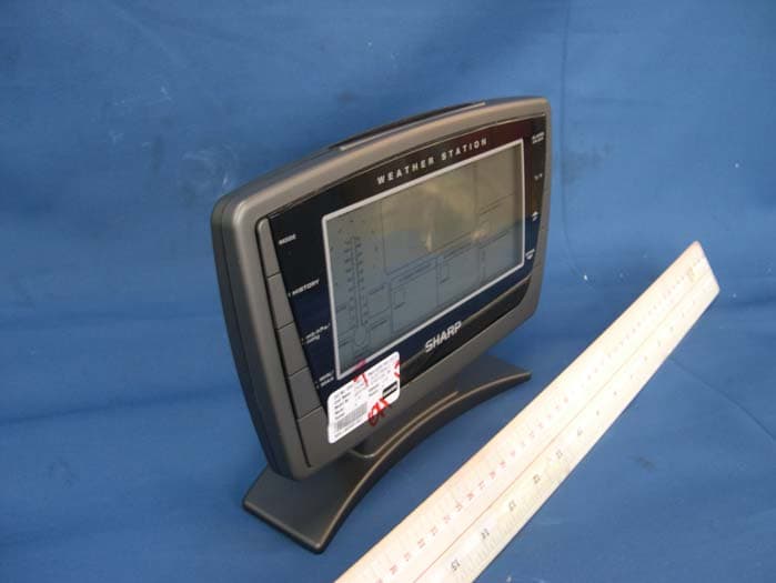
OQH-000000-10-001
Aug 29, 2010Wireless Weather Station
Equipment Class
CYY - Communications Receiver used w/Pt 15 Transmitter
OQH-000000-06-007
Aug 26, 2006Wireless Weather Station (433.9MHz Tx)
Equipment Class
DSC - Part 15 Security/Remote Control Transmitter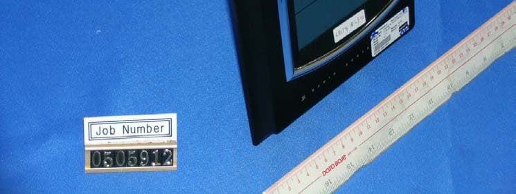
OQH-CHUNGS-05-004
Aug 29, 2005Wireless Weather Station (Receiver)
Equipment Class
CRR - Superregenerative Receiver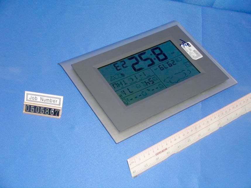
OQH-CHUNGS-05-003
Aug 29, 2005Wireless Weather Station (Receiver)
Equipment Class
CRR - Superregenerative Receiver