OQKSAT551
Telit Mobile Terminals S.p.A.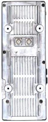
Click to zoom
Application Details
- Equipment Class
- AMP - Amplifier
- Date of Grant
- Jun 11, 2002
- Application Purpose
- Original Equipment
- Date of Application
- Mar 14, 2002
- Frequency Range
- 1610.00000000 - 1626.50000000
- Country
- Italy
Documents & Files
Document Text
Text extracted from the exhibit documents filed with the FCC. Open a document above to read the original.
Users Manual
1 Telit Sat 551 Car Kit for Telit Sat 550 Installation and Operation Guide 2 3 Contents Contents _______________________________________________3 Introduction _____________________________________________5 Safety Information _______________________________________6 Basic Pack ______________________________________________9 Cradle _________________________________________________11 Amplifier _______________________________________________11 Micro telephone _________________________________________11 Loudspeaker and microphone ______________________________11 Connecting wires for the vehicle IO devices ___________________12 Stereo mute feature ______________________________________12 Indication of switching on __________________________________13 Globalstar wire __________________________________________13 Globalstar magnetic external antenna ________________________13 GSM external antenna (optional) ____________________________14 Data connector __________________________________________14 Installation precautions __________________________________15 Installation example _____________________________________16 Installing the car kit _____________________________________17 Installing the amplifier (ODU) _______________________________17 Installing the cradle _______________________________________19 Connectors and keys on the cradle __________________________23 4 Installing the micro telephone ______________________________24 Installing the microphone __________________________________25 Installing the speaker _____________________________________26 Connecting to vehicle IO devices ____________________________27 Advice for wire routing ____________________________________28 Using the car kit ________________________________________29 Placing the Sat 550 in the cradle and removing it _______________29 Switching on the telephone and the car kit ____________________30 Hands-free mode ________________________________________30 Adjusting the volume in hands-free mode _____________________31 Using the micro telephone _________________________________31 Adjusting the volume on the micro telephone __________________32 Connecting to a Personal Computer _________________________32 Technical information ___________________________________33 5 Introduction This manual contains instructions for the correct installation and subsequent use of the car kit especially developed for the Telit Globalstar/GSM, Sat 550 model telephone. The main functions of the car kit comprise: t "hands free" function: enables to use the telephone while driving, in compliance with road safety laws; t option of conversation privacy by means of the included receiver; t telephone battery recharge function and stored power maintained during recharge; t option for connection to a portable computer by means of the standard serial port RS232. Please, read all instructions in this manual carefully to ensure correct installation of the car kit and exploit all device potential. In accordance with ongoing improvements, specifications, design and other descriptions in the present manual are subject to modifications without prior notice. The Manufacturer declines all liability for direct and/or indirect damage deriving from installation of this accessory. © Telit Mobile Terminals S.p.A. All rights reserved. EC Conformity Mark This car kit complies with European Community Standards ETS 300342 and ETS 300831; EN 60950 in terms of the provisions of European Directives: 99/5/EC 89/336/EEC 73/23/EEC and USA standards: FCC part 15 FCC part 25 6 Safety information In your car Always check on the laws and regulations governing the use of cellular telephones in force in the country in which you are driving. Should you use the telephone while driving, the following should always be adhered to: t Always pay maximum attention to your driving. t Only use your automobile kit where available. t Do not stop your car in the emergency lanes on a motorway to make or receive calls, only stop the vehicle in parking areas provided. Electronic devices Most electronic devices are protected by RF signals. Some electronic apparatus may not be sufficiently protected against RF signals emitted by the cellular telephone. Pacemakers t When the telephone is switched on always keep it at least 30 cm from pacemakers. t Do not keep the telephone in pockets near the thorax. t Use the ear on the opposite side from the pacemaker when using the telephone. t If you suspect any interference with the pacemaker, switch the telephone off immediately. Other medical devices If you are using the telephone near medical equipment, consult the manufacturer to ensure that it is adequately protected from RF signals. The telephone must be switched off in medical centres where this is expressly indicated. It is possible that medical equipment in use in hospitals and medical centres may be sensitive to RF signals. 7 Vehicles The use of cellular telephones inside vehicles may have a negative effect on their functioning, where these have not been correctly installed, and where RF signals emitted by the cellular phone have not been sufficiently shielded. Where there are warnings Always keep your telephone switched off wherever notices are posted expressly requesting this. Aircraft Standards set by aeronautical authorities forbid the use of telephones while an aircraft is flying. Telephones must always be switched off before boarding an aircraft. Locations where there is a danger of explosion The telephone must be switched off, and the battery must not be removed wherever there is a danger of explosion. Always comply with warnings and instructions. In such locations the smallest spark may cause explosion or fire. Areas that are subject to the danger of explosion are usually, but not always, clearly marked. These include, but are not limited to: filling stations like petrol garages, between decks on ships, depots or transhipment areas for fuels or chemicals, areas subject to the emission of fuel va…
Text truncated - open the document above for the full version.
Attestation Statements
34010 SGONICO (TRIESTE) – Viale Stazione di Prosecco, 5/b – tel. 040 / 41.92.111 – fax 040 / 25.11.11 MOBILE TERMINALS S.p.A. Sgonico, 29 th September 2000 Declarations for SAT551 Myself Paolo Giachin declares on behalf of Telit Mobile terminals S.P.A. that the product has changed his name during the final project phase from SV550 to SAT551. Therefore please consider the documentation related to the SV550 as for the SAT551. Sincerely, Paolo Giachin Product Development Manager Telephone Number +39 / 040 / 4192244 Fax Number +39 / 040 / 251257
Cover Letter(s)
FCC Laboratory Equipment Authorization Branch Examiners 7435 Oakland Mills Rd Columbia, MD 21036 Gentlemen: Submitted herewith is an application for a Part 25 car kit for a mobile handset transmitting on a frequency in the band 1610 to 1616 MHz. This rf amplifier allows hands free operation within a motor vehicle. The receiver system operates on a frequency of 2483.5 to 2500 MHz receiving signals for a series of LEO satellites. Antenna is roof mounted. If any additional information is needed, please let me know. Regards, Phil Inglis TRP/Cetecom bvba
Cover Letter(s)
34010 SGONICO (TRIESTE) – Viale Stazione di Prosecco, 5/b – tel. 040 / 41.92.111 – fax 040 / 25.11.11 MOBILE TERMINALS S.p.A. Sgonico, September 25, 2000Chief, Equipment Approval Services Federal Communications Commission P.O. Box 358315 Pittsburgh, PA 15251-5315 Agent Authorization Letter Dear Sir or Madam: We, Telit Mobile Terminals S.P.A., hereby authorize CETECOM ICT Services GmbH, Untertürkheimer Strasse 6 – 10, D-66117 Saarbrücken tel. +49/681/598-0 Germany to act as our agent in all matters relating to applications for equipment authorization, including the signing of all documents relating to these matters. This authorization expires on September 24, 2001. Sincerely, Paolo Giachin Product Development Manager Telephone Number +39 / 040 / 4192244 Fax Number +39 / 040 / 251257
Cover Letter(s)
34010 SGONICO (TRIESTE) – Viale Stazione di Prosecco, 5/b – tel. 040 / 41.92.111 – fax 040 / 25.11.11 MOBILE TERMINALS S.p.A. Sgonico, September 11, 2000Federal Communications Commission Authorization and Evaluation Division 7435 Oakland Mills Road Columbia, MD 21046 Confidentiality Request Letter Re: Request of Confidentiality Pursuant to Sections 0.457(d)(1)(ii) and 0.459 of the Commission’s Rules, the Applicant hereby requests confidential treatment of information accompanying as outlined below: Schematics, Technical Description, Block Diagram, Parts list The above materials contain trade secrets and proprietary information not customarily released to the public. The public disclosure of these matters might be harmful to the Applicant and provide unjustified benefits to its competitors. The Applicant understands that pursuant to Rule 0.457(d)(1)(ii), disclosure of this Application and all accompanying documentation will not be made before the date of the Grant for this Application. Sincerely, Paolo Giachin Product Development Manager Telephone Number +39 / 040 / 4192244 Fax Number +39 / 040 / 251257
Cover Letter(s)
Page 2 of 3 2.Manufacturers Declarations 2.1Antenna Port (Is a passive or temporary antenna port available?) Refer to Table A.2 from TBR 41:-Temporary antenna port is available 2.2Maximum antenna gain (if applicable). Attach gain results if necessary for outband peak measurements (see Annex D2 (d) from TBR 41):- 2.3Host equipment declaration (Is a host equipment required for the testing? If so, are repeat measurements on other set ups necessary?) All required host equipment must be supplied with the test sample. Refer to clause B4 from TBR 41:- SAT551 G* Antenna TX Gain -4 -3 -2 -1 0 1 2 3 4 5 6 151815281538154815581568157815881598160816181628163816481658166816781688169817081718 Frequency [MHz] Gain [dBi]
Cover Letter(s)
Mr. Dichoso: This is to follow up on the discussion with you on June 6 regarding the radiated test data for the SAT 551 car kit amplifier system from Telit. As you know, the radiated emissions testing was done as part of the European testing of the unit according to TBR 41 requirements. You indicated this was acceptable for measuring the levels of the radiated emissions, however, you asked for specific clarification of the equipment setup and for calculations of the radiated spurious levels of harmonics that would allow comparison of the levels with the Part 25 requirements. The radiated data covers the emissions outside the band of operation (1610 to 1626 MHz) over the range from 30 MHz to 12.75 GHz. During our conversation, the issue of radiated in band emission and the acceptance of the conducted data previously submitted for showing compliance was discussed. It was agreed that based on the conducted data, compliance with radiated in band requirements was shown. It was noted that in band emissions during normal operation would be connected to the supplied antenna and that the antenna gain would be applicable to emissions within the band of operation. Since compliance ratios between the fundamental emission and the modulation sidebands would be the same irrespective of whether the measurements were made on a conducted or radiated basis, actual radiated emissions in the band would not be required in this instance. The conducted ratios shown in the test report confirm compliance with in band emissions attenuation requirements. I have downloaded those pages out of the TBR41 test report (approximately 15 of the 233 pages) that pertain to the radiated emissions test to show compliance with the emissions requirements of Section 25.202(f) outside the 1.610 to 1.626 GHz band. According to Section 25.202(f)(3), the attenuation requirement for emissions in a 4 kHz band, the center frequency of which is removed from the assigned frequency by more than 250% of the authorized bandwidth is given by the formula 43 + 10log(power of the transmitter in watts). Transmit power for this system is 2 watts. 43 + 10 log(2) is equal to 46 dB. Thus the attenuation required is 46 dB below the power of the amplifier. The test setup is shown in Section 2 of the report. Configurations 2.1 and 2.2 show the basic set up in an anechoic chamber. Antennas were the EMCO series of biconnical, log periodic, and Model 3115 horn with an attached cable connecting to the spectrum analyzer. From the scan data as shown in Annex 3 charts 63 - 70, the only emissions of concern were the 2 nd and 3 rd harmonics. Based on your recommendation, I have computed the field strengths of these harmonics using the appropriate antenna factor, cable loss, and measured level of the signal based on the spectrum scan levels shown in the charts. The field strength was then used to compute the EIRP of the signal and serves as a basis for comparison with the fundamental EIRP power level. The data was scanned with a measurement separation distance of 0.5 meter to insure any low level emissions were captured. This allowed using a resolution bandwidth of 1 MHz while maintaining a sufficient signal to noise ratio. Since the levels were measured in a 1 MHz bandwidth, and the compliance requirement specifies an attenuation requirement for a 4 kHz bandwidth, the measured levels must be adjusted based on the ratios of the resolutions bandwidths according to 10log(4kHz/1MHz). This correction is applied to the measured levels and equals -24 dB. For the 2 nd harmonic, using the corrected reading as would be measured at 0.5 meter, the antenna factor and cable loss, the field strength is calculated according to -41 + 107 + 31 = 97 dBuV/m or 0.071 V/m at 0.5 meter. Using the formula E = Square root (30 x P)/R the calculated EIRP is 0.000042 watts equivalent to -44dBW or -14 dBm. For the 3 rd harmonic, using the same procedure as for the 2 nd harmonic, we calculate an EIRP level of 0.000017 watts equivalent -48 dBW or -18 dBm. As indicated in your correspondence dated May 23, 2002, the comparison for compliance is based on a radiated comparison with the antenna connected. With the antenna connected, the effective isotropic radiated power of the RF amplifier is +7.5 dBW or +37.5 dBm. From the above, 46 dB below +37.5 dBm is equivalent to: -46 + 37.5 = -8.5 dBm. Thus the power in any 4 kHz bandwidth cannot exceed -8.5 dBm. The tabulated levels follow: Frequency, MHzScan Level, @ 0.5 meter, 1MHz BW Corrected reading for 4 kHz BW Ant. Factor + cable loss, dB EIRP, dBm Limit, dBm Delta, dB 3236-17 dBm-41 dBm31 dB-14-8.55.5 4859-25 dBm-49 dBm35 dB-18-8.512.5 The above shows the RF amplifier meets the emissions levels as specified in Part 25 of the FCC rules on radiated basis by a margin of compliance of approximately 6 dB. Compliance on a conducted basis was shown in the previously submitted test report. A SAT 550 mobile satellite phone was used to provide the input signal to the RF amplifier. In previous correspondence it was indicated that use of the SAT 550 was acceptable for testing but the FCC would need to place a note on the grant limiting use of the RF amplifier to the SAT 550 satellite phone. Telit accepts that the grant will have a note restricting the RF amplifier car kit to use with the SAT 550 phone only. As a point of clarification, the SAT 550 phone has been previously certified under FCC ID: OQKSAT550. Regards, Phil Inglis, Cetecom bvba
External Photos
Rev. 0Telit Mobile Terminals S.p.A. TECHNICAL MANUAL Telit SV550 CAR KIT Page 1 of 9 Telital SV550 Car Kit final assembly front and rear view Rev. 0Telit Mobile Terminals S.p.A. TECHNICAL MANUAL Telit SV550 CAR KIT Page 2 of 9 Telital SV550 Car Kit final assembly lateral view Rev. 0Telit Mobile Terminals S.p.A. TECHNICAL MANUAL Telit SV550 CAR KIT Page 3 of 9 Out Door Unit for SV550 Car kit assembly front and rear view
External Photos
CETECOM ICT Services GmbH Test report no.: 2-1601-02-04/99 Photo no.: 26
ID Label/Location Info
ITEMS REQUIRED FOR AN FCC CERTIFICATION SUBMITTAL FCC Part 2, Paragraph 2.1033 Page 14 of 14 LABEL Scale 1:2 The label will be placed on the lower side of the cradle. The compliance statement appears in the User Manual. 16) Photographs* of the equipment clear enough to reveal: Equipment construction and layout, including meters, and labels for controls and meters; Internal construction defining component placement and chassis assembly. The photographs and other information required at this point are available in the Technical manual and in the Test reports. 17) If equipment is an AM broadcast sterophonic exciter-generator intended for interfacing with existing certified, or formerly type accepted or notified transmitters must include measurements made on a complete stereophonic transmitter. The instruction book must include complete specifications and circuit requirements. For interconnecting with existing transmitters. The instruction book must also provide a full description of the equipment and measurement procedures to monitor modulation and to verify that the combination of stereo exciter-generator and transmitter meet the emission limitation of 73.44. The equipment is not an AM broadcast sterophonic exciter
RF Exposure Info
RF exposure instructions Pursuant to 47 CFR § 25.200(d) of the FCC Rules and Regulations, this equipment is subject to the radio frequency radiation exposure requirements specified in § 1.1307(b), § 2.1091 and § 2.1093, as appropriate. The Telit car kit adapter is intended to provide a means of using a handset in a cradle for the purpose of communicating with a satellite from inside an automobile. The car kit system is an rf amplifier unit, trunk mounted, with a cradle that accepts the handset unit that is normally used by the individual for communicating via the satellite with other ground based users of the telecom network. RF signals from the handset are routed by the cradle to the rf amplifier unit which uses a roof top magnetic mount antenna (this is the antenna supplied by Telit) for transmission and reception. The device transmits in the 1610 to 1626.5 MHz band and receives in the 2483.5 to 2500 MHz band and uses the external magnetic mount antenna for roof top mounting. Telit certifies that it has determined that the rf amplifier unit with car top antenna complies with the RF hazard requirements applicable to this equipment operating under the authority of 47 CFR Part 25 of the FCC Rules and Regulations. This determination is dependent upon installation, operation and use of the equipment in accordance with all instructions provided. The Telit system configured with the car kit external amplifier is defined by the FCC Rules as a mobile device which according to FCC definitions means that the device is designed to be used in other than fixed locations and generally in such a way that a separation distance of at least 20 cm (8 inches) is normally maintained between the transmitter's antenna and the body of the user or nearby persons. The car kit amplifier is not designed for or intended to be used in portable applications (within 20 cm of the body of the user) and such uses are strictly prohibited. To ensure that the car kit complies with current FCC regulations limiting both maximum RF output power and human exposure to radio frequency radiation, a separation distance of at least 20 cm must be maintained between the unit's antenna and the body of the user and any nearby persons at all times and in all applications and uses. Further, when installed as directed with the magnetic roof mount antenna, there will be additional shielding of the radiation by the metallic roof of the vehicle in which the car kit is installed. In addition, the antenna pattern from the roof mount antenna is directed upward towards the nominal satellite position overhead away from anyone inside the automobile. MPE calculated energy level: Using 7.5 Watts EIRP, 20 cm separation distance, the calculated power distance computed by dividing the EIRP by the surface area of a sphere of 20 cm diameter is 1.49 mW/cm 2 . From the above, there is an intervening metallic plate to reduce the electric field by virtue of the magnetic base in the antenna and further, the antenna design is such to radiated the energy upward away from the passenger compartment of an automobile. Based on the above, Telit certifies that the FCC requirements for mobile MPE limits for RF Exposure are met by their product.
RF Exposure Info
RF exposure instructions Pursuant to 47 CFR § 25.200(d) of the FCC Rules and Regulations, this equipment is subject to the radio frequency radiation exposure requirements specified in § 1.1307(b), § 2.1091 and § 2.1093, as appropriate. The Telit car kit adapter is intended to provide a means of using a handset in a cradle for the purpose of communicating with a satellite from inside an automobile. The car kit system is an rf amplifier unit, trunk mounted, with a cradle that accepts the handset unit that is normally used by the individual for communicating via the satellite with other ground based users of the telecom network. RF signals from the handset are routed by the cradle to the RF amplifier unit, which uses a roof top magnetic mount antenna (this is the antenna supplied by Telit) for transmission and reception. The device transmits in the 1610 to 1626.5 MHz band and receives in the 2483.5 to 2500 MHz band and uses the external magnetic mount antenna for roof top mounting. Telit certifies that it has determined that the rf amplifier unit with car top antenna complies with the RF hazard requirements applicable to this equipment operating under the authority of 47 CFR Part 25 of the FCC Rules and Regulations. This determination is dependent upon installation, operation and use of the equipment in accordance with all instructions provided. The Telit system configured with the car kit external amplifier is defined by the FCC Rules as a mobile device which according to FCC definitions means that the device is designed to be used in other than fixed locations and generally in such a way that a separation distance of at least 20 cm (8 inches) is normally maintained between the transmitter's antenna and the body of the user or nearby persons. The car kit amplifier is not designed for or intended to be used in portable applications (within 20 cm of the body of the user) and such uses are strictly prohibited. To ensure that the car kit complies with current FCC regulations limiting both maximum RF output power and human exposure to radio frequency radiation, a separation distance of at least 20 cm must be maintained between the unit's antenna and the body of the user and any nearby persons at all times and in all applications and uses. Further, when installed as directed with the magnetic roof mount antenna, there will be additional shielding of the radiation by the metallic roof of the vehicle in which the car kit is installed. In addition, the antenna pattern from the roof mount antenna is directed upward towards the nominal satellite position overhead away from anyone inside the automobile. MPE calculated energy level: Using 7.5 Watts EIRP, 20 cm separation distance, the calculated power distance computed by dividing the EIRP by the surface area of a sphere of 20 cm diameter is 1.49 mW/cm 2 . From the above, there is an intervening metallic plate to reduce the electric field by virtue of the magnetic base in the antenna and further, the antenna design is such to radiated the energy upward away from the passenger compartment of an automobile. Based on the above, Telit certifies that the FCC requirements for mobile MPE limits for RF Exposure are met by their product. RF EXPOSURE ISSUES AND CALCULATION Joe, the calculation is to be based on the following analysis. The test report lists an ERIP level of 7.5 dBW based on a measured conducted power of 33 dBm with an antenna gain of 4.5 dB. 7.5 dBW EIRP is equivalent to a power level of 5.62 watts EIRP. Substituting in the equation, P (watts)/A (surface area of a sphere with radius 20 cm)), yields a power density of 1.12 mW/cm 2 in the direction of maximum antenna gain at a distance of 20 cm. However, this power density only occurs in the direction of maximum gain, which for a mobile antenna used in a mobile to satellite communication system would be in the vertical direction skyward away from the operator in the vehicle. Twenty centimeters was used in the above calculation because this is the minimum distance that defines a mobile device. For any normal installation there would be more than 20 cm (8 inches) separating the operator or the public from the roof mounted antenna, (see the user manual, Page 16). This figure shows a typical installation with the antenna approximately mid point mounted on the roof of the car. A metallic roof is required since the antenna would not hold on any other surface. As previously explained the antenna pattern is directed upward away from the operator or any pedestrian along side the car. With a mid point roof mount, the distance to the edge of the car would be approximately 24 inches or greater. With a magnetic mount antenna on the roof of a car, the main lobe of the antenna directed vertically into the sky, and a metallic plate between the operator and the antenna, it is reasonable to conclude that an operator in the car could not under any circumstances be subjected to a field that approached the 1 mW/cm 2 limit. As for a pedestrian adjacent to the car, with the antenna mounted on the roof at its mid point as shown, the distance would between the antenna and a pedestrian would be at least of the order of 25 cm or 10 inches. Recalculating for a separation distance of 25 cm, we get a power density of 0.715 mW/cm 2 at 25 cm. At 61 cm (24 inches) the power density will be much lower or 0.12 mW/cm 2 . Based on the above, it is reasonable to conclude that a pedestrian adjacent to the car will not be exposed to fields exceeding the MPE limit of 1 mW/cm 2 . A statement will be added to the instruction manual as follows: "The roof mount antenna should be mounted near the center of the roof of the vehicle, but in no instance closer than 25 cm (approximately 10 inches) from the edge of the roof."
Test Report
CETECOM ICT Services GmbH Test report no.: 2-1601-02-04/99 date: 07.07.2000 page 1 (60) Test report no.: 2-1601-02-04/99 SV550 Accredited testing laboratory DAR-Registration number: TTI-P-166/98 CETECOM ICT Services GmbH Test report no.: 2-1601-02-04/99 date: 07.07.2000 page 2 (60) Table of contents 1 General Information ......................................................................................................................................................... 3 1.1 Notes......................................................................................................................................................................... 3 1.2 Test laboratory.......................................................................................................................................................... 4 1.3 Applicant ́s details .................................................................................................................................................... 4 1.4 Details of application ................................................................................................................................................ 4 1.5 Test item ................................................................................................................................................................... 5 1.5.1 General description............................................................................................................................................... 5 1.5.2 Operating conditions............................................................................................................................................. 7 1.6 Test standard(s) ........................................................................................................................................................ 7 2 Technical test.................................................................................................................................................................... 9 2.1 Summary of test results ............................................................................................................................................ 9 2.2 Test environment ...................................................................................................................................................... 9 2.3 Measurement and test setup, measurement uncertainties ......................................................................................... 9 2.4 Test equipment utilized ............................................................................................................................................ 9 2.5 Test results.............................................................................................................................................................. 11 2.5.1 Test result overview............................................................................................................................................ 11 2.5.2 Test documentation............................................................................................................................................. 12 Enclosure Annex 1: Measurement and test setups - schematic diagrams Annex 2: Measuring equipment used (statement of inventory) Annex 3: Measurement results Annex 4: Data of correction Annex 5: Photographs Annex 6: Technical description(s) of the test item CETECOM ICT Services GmbH Test report no.: 2-1601-02-04/99 date: 07.07.2000 page 3 (60) • General Information • Notes The test results of this test report relate exclusively to the test item specified in subclause 1.5. ́CETECOM ICT Services GmbH ́ does not assume responsibility for any conclusions and generalizations drawn from the test results with regard to other specimens or samples of the type of the equipment represented by the test item. The test report may only be reproduced or published in full. Reproduction or publication of extracts from the report requires the…
Text truncated - open the document above for the full version.
Contact Information
Applicant
Mario Fragiacomo(Technical Director)
39 040 4192244Fax: 39 040 251257
Technical Contact
TRP/Cetecom bvbaPhillip Ingilos
[email protected]410 531 3439
14085 Howard Rd · Dayton, Maryland · United States
Non-Technical Contact
TRP/Cetecom bvbaPhillip Inglis
[email protected]410 531 3439
Test Firm
Cetecom ICT Services GmbHRalf Hoehn
Technical Specifications
| # | Rule Parts | Frequency Range | Power Output | Emission | Tolerance |
|---|---|---|---|---|---|
| 1 | 25 | 1.61 GHz - 1.63 GHz | 2 W | 1M45G9W | 2.5000000000 ppm |
Other Applications from Telit Mobile Terminals S.p.A.
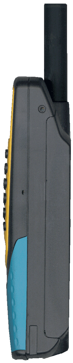
OQKSAT600
May 27, 2002Mobile Phone for Satellite Reception
Equipment Class
TNE - Licensed Non-Broadcast Transmitter Held to Ear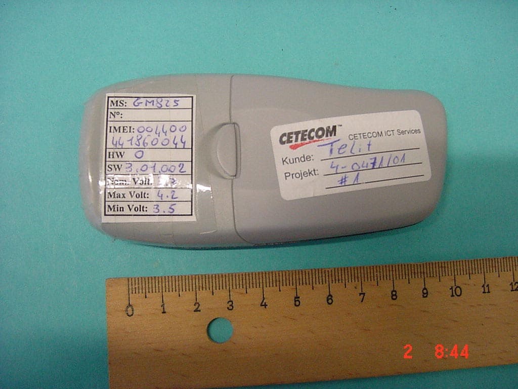
OQKGM825
Feb 25, 2002Licensed Portable
Equipment Class
PCE - PCS Licensed Transmitter held to ear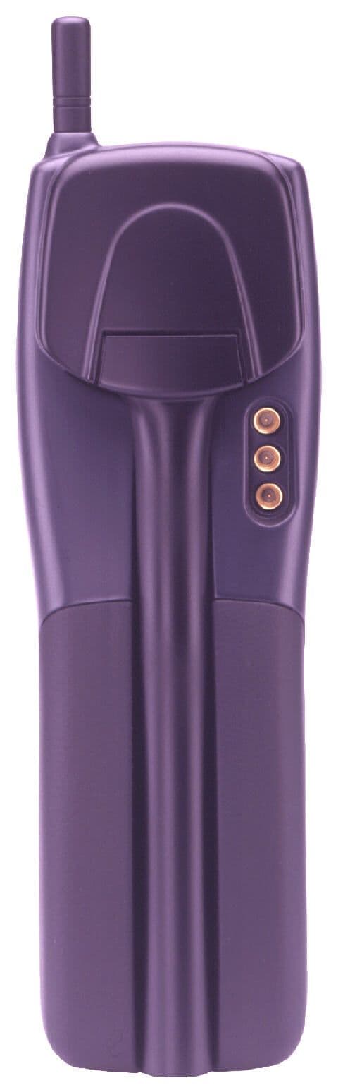
OQKSAT550
Apr 04, 2000TELITAL SAT 550 DUAL MODE PORTABLE MOBILE EARTH ST
Equipment Class
TNE - Licensed Non-Broadcast Transmitter Held to Ear