OR7GL3001Free Board 2FT
Globlink Technology Inc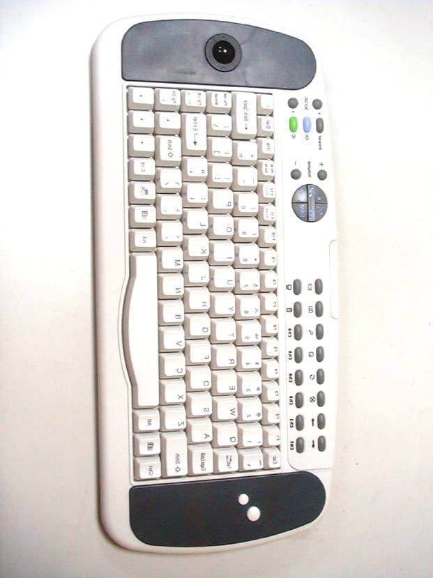
Click to zoom
Application Details
- Equipment Class
- DXX - Part 15 Low Power Communication Device Transmitter
- Date of Grant
- Jun 27, 2001
- Application Purpose
- Original Equipment
- Date of Application
- May 01, 2001
- Equipment Note
- Free Board 2FT
- Frequency Range
- 26.98500000 - 27.26000000
- Company
- Globlink Technology Inc
- Country
- Taiwan
Documents & Files
Document Text
Text extracted from the exhibit documents filed with the FCC. Open a document above to read the original.
ID Label/Location Info
LABEL Format: This device complies with Part 15 of the FCC Rules Operation is subject to the following two conditions: (1) This device may not cause harmful interference, and (2) This device must accept any interference received, including interference that may cause undesired operation Model No.:GL3001 FCC ID:OR7GL3001 LABEL Size: 60 x 30 mm LABEL Position:
Operational Description
88 KBT system description Define by Panny Tam 01/06/26 11:31 AM Free board 2FT transmitter 1. MCU will scan the key matrix, ID key, channel key and the movement of track ball. If any signal change come from above mention. It will turn convert the data package with checking the low battery status data, and prepare for modulate to the VCO directly. 2. When MCU received the signal of any key, or from track ball. Firstly, MCU will turn on the RF power, program the synethizer code of PLL( phase lock loop), PLL will lock the exact frequency.( eg. 26.985MHz) 3. The reference LO( local oscillator) will support the exact 10.24MHz to the PLL and VCO, to compare the phase to let VCO to lock the exact frequency(e.g. 26.985MHz) 4. Buffer amplifier is to change the impedance between VCO (high impredance) to low impredance 5. (PA)Power amplifier is to support enough current to drive the antenna 6. Matching circuit is to match the impredance between PA and antenna. Free board 2FT receiver 1. When the PC power on, the receiver will start the PnP process. No-matter the interface is PS2 or USB 2. MCU will program the synethizer code of PLL( phase lock loop), PLL will lock the exact frequency.( eg. 37.680MHz) of VCO 3. When the RF signal comes(e.g. 26.985MHz), the low noise amplifier (LNA) will amplify the signal about 14 dB. 4. The adding signal to pass through mixer 1 will generate 10.695MHz intermediate frequency(IF). It means that the original signal (26.985MHz) will down convert to 10.695MHz 5. IF1 filter is perform a filtering function of 10.695MHz (IF1) 6. Reference crystal not only perform the reference function, and also with the local oscillator (LO)function 7. When the IF signal pass through the second mixer, it will generate the second IF2 455KHz. 8. After the IF2 amplifier will work for a AGC (auto gain control) function, and the signal more stable 9. A 455KHz resonator will perform the LO function. 10. When the IF2(455KHz) pass through discriminator, the demodulating signal will come out. We called it base band signal. 11. AF AMP will work as a data slicer, it amplify the signal to square wave digital signal. 88 KBT system description Define by Panny Tam 01/06/26 11:31 AM 12. This digital signal will send to MCU. MCU will sample the signal to check it is valid or not. 13. If the signal it valid, MCU will convert the signal of the interface to PC. No- matter is PS2 or USB and let PC to do their exact activity. 14. MCU also scan the reset lock key to check user has to press this key or not.
Test Report
Test Report -------------------------------------------------------------------------------- 2/14 Report No.: G2815148T Training Research Co., Ltd., TEL: 886-2-26935155, Fax: 886-2-26934440 Contents Chapter 1 Introduction Description of EUT...................................................................................................................3 Configuration of Test Setup......................................................................................................4 List of Support Equipment........................................................................................................5 Chapter 2 Conducted Emission Test Test Condition and Setup..........................................................................................................6 Chapter 3 Radiated Emission Test Test Condition and Setup..........................................................................................................7 Radiated Test Placement...........................................................................................................9 Appendix A : Radiated test result...................................................................................................................10 Appendix B : Band Edge of Measurement.....................................................................................................13 Test Report -------------------------------------------------------------------------------- 3/14 Report No.: G2815148T Training Research Co., Ltd., TEL: 886-2-26935155, Fax: 886-2-26934440 Chapter 1Introduction Description of EUT: EUT:Free Board 2FT Model No.:GL3001 FCC ID:OR7GL3001 Frequency Range:26.96 – 27.28 MHz Power Type:Powered by two 1.5VDC batteries This wireless keyboard with track ball use advanced transmission technology to allow comfortable use. However, occasionally outside sources may cause interference. Test method: All measurements contained in this report were performed according to the techniques described in Measurement procedure ANSI C63.4 – 1992. Pretest was found that the emission of operating mode is worse than standby mode. So, The final test is made at the operating mode. While testing, the EUT was made to transmit continuously and adjusted at a position, which transmitted the maximum emission. The test placement as the photographs showed is the worst case emission placed. (If the emission is close to the ambient, the resolution BW and view resolution will be reduced and the data will be recorded by detection of maximum hold peak mode.) The testing configuration of test setup is showing in the next page. Test Report -------------------------------------------------------------------------------- 4/14 Report No.: G2815148T Training Research Co., Ltd., TEL: 886-2-26935155, Fax: 886-2-26934440 Configuration of Test Setup Connections: EUT: Put two AAA size, 1.5V battery into the battery cell of EUT, powers the subject device. The EUT does not be connected with any product. EUT (Tx) Support Equipment Located Remotely PC Monitor Power (Rx) Test Report -------------------------------------------------------------------------------- 5/14 Report No.: G2815148T Training Research Co., Ltd., TEL: 886-2-26935155, Fax: 886-2-26934440 List of Support Equipment: Conducted (Radiated) test: PC:HP Brio 85xx 6/350 Model No.:D6928A Serial No. :TW90400174 FCC ID:N/A, Doc Approved :3872H013 Power type:100 ~ 230VAC / 50 ~ 60Hz, 5A, Switching Power cord :Non-shielded, 2.33m long, Plastic, No ferrite core Monitor :HP 15’ Color Monitor Model No.:D2832A Serial No.:MY90615892 FCC ID:N/A, Doc Approved :4872A167 Power type:100 ~ 240 VAC / 50 ~ 60 Hz, Switching Power cord:Shielded, 1.80m long, No ferrite core Data cable :Shielded, 1.50m long, with two ferrite cores Rx:GLOBLINK TECHNOLOGY INC. Model No.:GL3001 FCC ID:N/A, Doc Approved Power type:Powered by PC Data cable :Non-shielded, 1.50m (Keyboard) and 1.90m (Mouse) long, no ferrite core Test Report -------------------------------------------------------------------------------- 6/14 Report No.: G2815148T Training Research Co., Ltd., TEL: 886-2-26935155, Fax: 886-2-26934440 Chapter 2Conducted Emission Test Test Condition and Setup: All the equipment is placed and setup according to the ANSI C63.4 – 1992. The EUT is assembled on a wooden table, which is 80 cm high, is placed 40 cm from the back-wall, which is a vertical conducting plane. One LISN is for EUT, the other LISN is for support equipment. They are all placed on the conductive ground. The EUT’s LISN connect a line switch box for selecting L1 or L2, then connect to a preamplifier and spectrum. The spectrum scans from 150KHz to 30MHz. Conducted emission levels are detected at max. peak mode . But if the max. peak mode failed or over average limit, it will be measured by average detection mode. While testing, there is the worst-emission plot printed at peak detection mode, and there are more than 6 highest emissions relative to limit recorded. The plot is kept as the original data, not included in test report. List of test Instrument: Calibration Date Instrument Name Model No. Brand Serial No. Last time Next time Spectrum analyzer8591EMH P 3619A0120302/22/0102/22/02 Pre-selector (<30MHz)AMP-01TRCREP-00108/09/0008/09/01 LISN (EUT)TRC LISN01TRCLISN-0108/21/0008/21/01 LISN (Support E.)LISN01TRC9912-01, 0212/02/0012/02/01 The level of confidence of 95%, the uncertainty of measurement of conducted emission is ± 2.4 dB. Test Result: N/A Test Report -------------------------------------------------------------------------------- 7/14 Report No.: G2815148T Training Research Co., Ltd., TEL: 886-2-26935155, Fax: 886-2-26934440 Chapter 3 Radiated Emission Test Test Condition and Setup: Pretest : Prior to the final test ,the EUT is placed in an anechoic chamber, and scan from 30MHz to 1GHz. The devices rotated through three orthogonal axes to determine which attitude and configuration produces the highest emission relative to the limit. This is done …
Text truncated - open the document above for the full version.
Contact Information
Applicant
Eric Weng(Manager)
Technical Contact
TRAINING RESEARCH CO., LTD.JACK TSAI
[email protected]886-2-26935155
NO. 2, LANE 194, HUAN HO STREET, · TAIPEI HSIEN, · Taiwan
Non-Technical Contact
TRAINING RESEARCH CO., LTD.JACK TSAI
Test Firm
Training Research Co., Ltd.Jack Tsai
Technical Specifications
| # | Rule Parts | Frequency Range | Power Output |
|---|---|---|---|
| 1 | 15C | 26.985 MHz - 27.26 MHz | - |
Other Applications from Globlink Technology Inc

OR7GM521
Feb 24, 2008Wireless Ring Mouse
Equipment Class
DXX - Part 15 Low Power Communication Device Transmitter
OR7GM322
Sep 15, 2007Wireless Free Wheel Mouse
Equipment Class
DXX - Part 15 Low Power Communication Device Transmitter
OR7GM323
Sep 15, 2007Wireless Free Wheel Mouse
Equipment Class
DXX - Part 15 Low Power Communication Device Transmitter
OR7GM520
Sep 11, 2007Wireless Big Optical Trackball Mouse
Equipment Class
DXX - Part 15 Low Power Communication Device Transmitter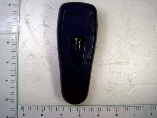
OR7GP300
Dec 11, 20062.4 GHz RF Wireless Optical Presentation Mouse
Equipment Class
DXX - Part 15 Low Power Communication Device Transmitter