OR7GT920Wireless Key Pad
Globlink Technology Inc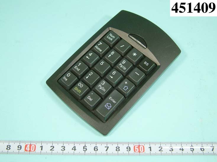
Click to zoom
Application Details
- Equipment Class
- DXX - Part 15 Low Power Communication Device Transmitter
- Date of Grant
- Jun 07, 2004
- Application Purpose
- Original Equipment
- Date of Application
- Jun 07, 2004
- Equipment Note
- Wireless Key Pad
- Frequency Range
- 27.12000000 - 27.12000000
- Company
- Globlink Technology Inc
- Country
- Taiwan
Documents & Files
Document Text
Text extracted from the exhibit documents filed with the FCC. Open a document above to read the original.
Users Manual
EUROPEAN STATEMENT Hereby, Globlink Technologies Inc., declares that this 27 MHz Wireless keyboard is in compliance with the essential requirements and other relevant provisions of the R&TTE Directive 1999/5/EC. This device will be sold in the following EEA countries: Austria, Italy. Belgium, Liechtenstein. Denmark, Luxembourg. Finland, Netherlands. France, Norway. Germany, Portugal. Greece, Spain. Iceland, Sweden. Ireland, United Kingdom. FEDERAL COMMUNICATIONS COMMISSION This device complies with Part 15 of the FCC Rules. Operation is subject to the following two conditions:(1) this device may not cause harmful interference, and (2) this device must accept any interference received, including interference that may cause undesired operation. NOTE This equipment has been tested and found to comply with the limits for a Class B digital device, pursuant to Part 15 of the FCC Rules. These limits are designed to provide reasonable protection against harmful interference in a residential installation. This equipment generates, uses and can radiated radio frequency energy and, if not installed and used in accordance with the instructions, may cause harmful interference to radio communications. However, there is no guarantee that interference will not occur in a particular installation If this equipment does cause harmful interference to radio or television reception, which can be determined by turning the equipment off and on, the user is encouraged to try to correct the interference by one or more of the following measures: -Reorient or relocate the receiving antenna. -Increase the separation between the equipment and receiver. -Connect the equipment into an outlet on a circuit different from that to which the receiver is connected. -Consult the dealer or an experienced radio/TV technician for help. Changes or modifications not expressly approved by the party responsible for compliance could void the user‘s authority to operate the equipment. This device and its antenna(s) must not be co-located or operating in conjunction with any other antenna or transmitter. The manufacturer is not responsible for any radio or TV Interference caused by unauthorized modifications to this equipment. Such modifications could void the user's authority to operate the equipment. Key Pad Remove the battery cover and insert the alkaline batteries ID Code Configuration: 1. Press the setup key on the RECEIVER to unlock the receiver, the “Lock LED” light turns off. Press the setup key on the bottom of the MOUSE. when the Lock light on the receiver is lit, the mouse is set up with a random ID well and the receiver is locked. 2. Please unlock the receiver again. Press the setup key on the KEY PAD, when the Lock light on the receiver is lit, the KEY PAD is set up with a random ID well and the receiver is locked. RF mini optical mouse and Key pad are assigned with 4096 ID’s: To avoid potential interference, the receiver is automatically locked after configuration. Ensure the receiver is unlocked before configuration or the product will not function. ID KEY Lock LED Setup key Reciver Battery insert Key Pad Re-install or re-insert the batteries: Please configure ID code again every time you re-insert the batteries. Program Resolution: The default resolution of mini optical mouse is 800CPI, it can be programmed to 400CPI by re-inserting the batteries while pressing the wheel button of the mouse. If go back to default 800CPI, just re-insert the batteries again without pressing the wheel button of the mouse Software Installation: Insert the attached CD driver in your CD-Rom drive. Execute the “setup.exe” to complete the installation. After installation, please re-start your PC. Battery low checking: Please point the sign showed on your computer screen to check the power situation of the battery for Mouse and Key Pad Num 7 8 45 1 2 0 /* BS + ON/OFF SW De/Activate Number Lock of Key pad: 1. Activate “Number Lock” ● Noted: The factory default is to activate “Number Lock” function Definition of the keys Num Lock / * BS 7 8 9 - 4 5 6 + 1 2 3 0 00 . Enter 2. De-activate Number Lock Definition of the keys Num Lock * BS HOME PgUp - + END PgDn INS Shift DEL Enter 3. Deactivate “Num Lock”, press “Shift” and one of the key simultaneously, the definition of the keys becomes: Num Lock & % BS ( : ) $ < , > Web/Home TAB Ins Space Shift = Email Warning: There is a risk of explosion if you use different types of batteries at the same time ( Such as alkaline battery plus rechargeable battery )
External Photos
APPENDIX A. Photographs of EUT
ID Label/Location Info
FCC ID: OR7GT920 Label Location
Internal Photos
REPORT NO. : F451409 SPORTON International Inc. PAGE NUMBER : A1 OF A1 TEL : 886-2-2696-2468 ISSUED DATE : Jun. 03, 2004 FAX : 886-2-2696-2255 REPORT NO. : F451409 SPORTON International Inc. PAGE NUMBER : A2 OF A2 TEL : 886-2-2696-2468 ISSUED DATE : Jun. 03, 2004 FAX : 886-2-2696-2255 REPORT NO. : F451409 SPORTON International Inc. PAGE NUMBER : A3 OF A3 TEL : 886-2-2696-2468 ISSUED DATE : Jun. 03, 2004 FAX : 886-2-2696-2255 REPORT NO. : F451409 SPORTON International Inc. PAGE NUMBER : A4 OF A4 TEL : 886-2-2696-2468 ISSUED DATE : Jun. 03, 2004 FAX : 886-2-2696-2255
Operational Description
FCC ID: OR7GT920 Description of Operation EUT is a Wireless Key Pad with hot Key Function. This device provided transmitting data rate up to 5Kbps. The device optimized for 27MHz worldwide wireless application and RF carrier is FSK. The antenna is Printed Antenna, and there is no antenna connector. This Wireless Key Pad is a Wireless FSK adapter. It allows you to connect to your computer and other USB interface resources. This device has excellent operating performance with Notebook PC & desktop PC. Especially under less interference environment, the operating distance will be more perfect without any angel limit. The EUT is a Wireless Key Pad can Remote to Computer And other the USB interface of solution.
Test Report
FCC ID: OR7GT920 Issued on Jun. 03, 2004 Report No.: F451409 SPORTON International Inc. TEL : 886-2-2696-2468 FAX : 886-2-2696-2255 FCC TEST REPORT CATEGORY: Mobile End Product PRODUCT NAME: 27MHz Wireless keyboard FCC ID.: OR7GT920 FILING TYPE: Certification MODEL NAME: GT-920 for keyboard GT-910 for receiver BRAND NAME: Globlink, TRUST, CENTRIOS, RADIOSHACK, NEXXTECH APPLICANT: Globlink Technology Inc. 2Fl., 101 Rui-hu Street Nei-hu(114), Taipei , Taiwan MANUFACTURER: Same as Applicant ISSUED BY: SPORTON INTERNATIONAL INC. 6F, No. 106, Sec. 1, Hsin Tai Wu Rd., His Chih, Taipei Hsien, Taiwan, R.O.C. Statements: The test result in this report refers exclusively to the presented test model / sample. Without written approval of SPORTON International Inc., the test report shall not be reproduced except in full. Certificate or Test Report could not be used by the applicant to claim the product endorsement by CNLA, NVLAP or any agency of U.S. government. The test equipment used to perform the test are calibrated and traceable to NML/ROC or NIST/USA. Dr. Alan Lane Vice General Manager SPORTON International Inc. Lab Code: 200079-0 FCC ID: OR7GT920 Issued on Jun. 03, 2004 Report No.: F451409 SPORTON International Inc. FCC ID. : OR7GT920 TEL : 886-2-2696-2468 Page No. : i FAX : 886-2-2696-2255 Issued Date : Jun. 03, 2004 Table of Contents History of this test report....................................................................................................................................ii 1. General Description of Equipment Under Test ............................................................................................1 1.1. Applicant..........................................................................................................................................................................................1 1.2. Manufacturer ...................................................................................................................................................................................1 1.3. Basic Description of Equipment under Test ....................................................................................................................................1 1.4. Features of Equipment under Test..................................................................................................................................................1 2. Test Configuration of the Equipment Under Test ........................................................................................2 2.1. Description of the Test ....................................................................................................................................................................2 2.2. Frequency Range Investigated .......................................................................................................................................................2 2.3. Details of the Supporting Units........................................................................................................................................................2 2.4. Connection Diagram of Test System ..............................................................................................................................................2 3. Test Software ...................................................................................................................................................3 4. Test Location and Standards .........................................................................................................................4 4.1. Test Location...................................................................................................................................................................................4 4.2. Test Standards ................................................................................................................................................................................4 5. Band Edge ........................................................................................................................................................5 5.1. Measuring Instruments....................................................................................................................................................................5 5.2. Test Procedures ..............................................................................................................................................................................5 5.3. Test Setup Layout ...........................................................................................................................................................................6 5.4. Test Results ....................................................................................................................................................................................7 6. Carrier Field Strength......................................................................................................................................8 6.1. Measuring Instruments....................................................................................................................................................................8 6.2. Test Procedures ..............................................................................................................................................................................8 6.3. Test Setup Layout ...........................................................................................................................................................................9 6.4. Test Results and Limit...................................................................................................................................................................10 7. Conducted Emission Measurement .........................................…
Text truncated - open the document above for the full version.
Test Setup Photos
1.1. Photographs of Radiated Emission Test Configuration z The photographs show the configuration that generates the maximum emission. FRONT VIEW REAR VIEW
Contact Information
Applicant
Eric Weng(Manager)
Technical Contact
Sporton International Inc.Alan Lane
[email protected]+883-3-327-3456
No. 52 Hwa ya First Road, Hwa Ya Technology Park · Taoyuan · Taiwan
Test Firm
SPORTON International IncKathy Lin
Technical Specifications
| # | Rule Parts | Frequency Range | Power Output |
|---|---|---|---|
| 1 | 15C | 27.12 MHz - 27.12 MHz | - |
Other Applications from Globlink Technology Inc

OR7GM521
Feb 24, 2008Wireless Ring Mouse
Equipment Class
DXX - Part 15 Low Power Communication Device Transmitter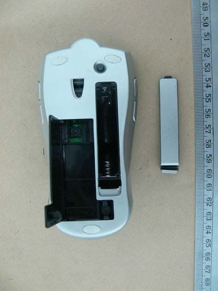
OR7GM322
Sep 15, 2007Wireless Free Wheel Mouse
Equipment Class
DXX - Part 15 Low Power Communication Device Transmitter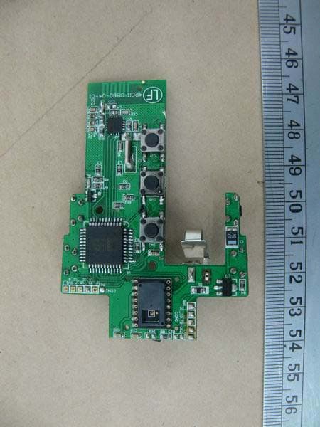
OR7GM323
Sep 15, 2007Wireless Free Wheel Mouse
Equipment Class
DXX - Part 15 Low Power Communication Device Transmitter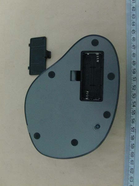
OR7GM520
Sep 11, 2007Wireless Big Optical Trackball Mouse
Equipment Class
DXX - Part 15 Low Power Communication Device Transmitter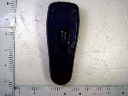
OR7GP300
Dec 11, 20062.4 GHz RF Wireless Optical Presentation Mouse
Equipment Class
DXX - Part 15 Low Power Communication Device Transmitter