ORFWAYNETRAC
Wayne Fueling Systems LLC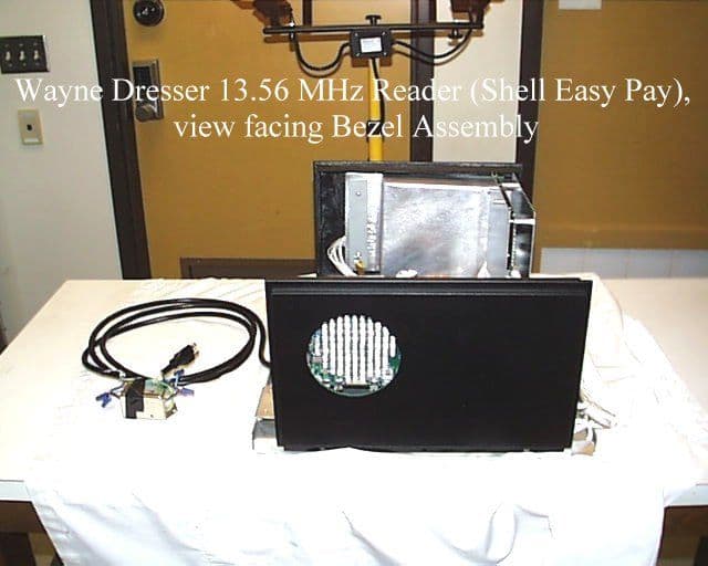
Click to zoom
Application Details
- Equipment Class
- DXX - Part 15 Low Power Communication Device Transmitter
- Date of Grant
- Feb 16, 2000
- Application Purpose
- Original Equipment
- Date of Application
- Oct 28, 1999
- Frequency Range
- 13.56000000 - 13.56000000
- Company
- Wayne Fueling Systems LLC
- Country
- United States
Documents & Files
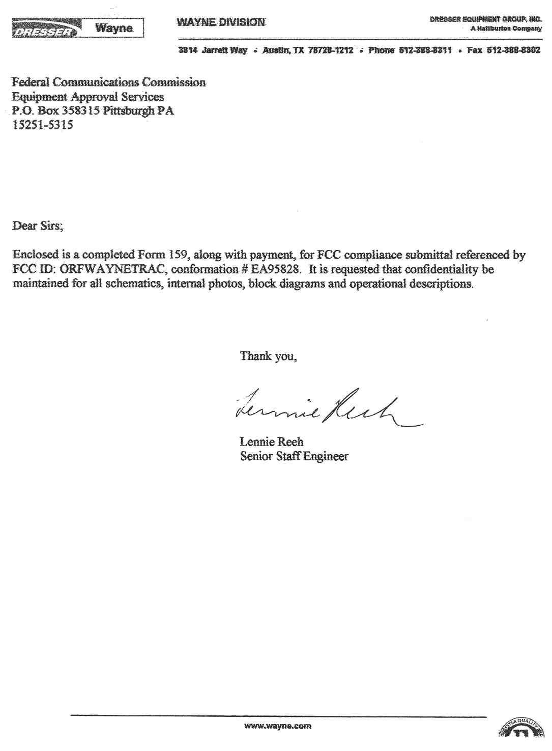
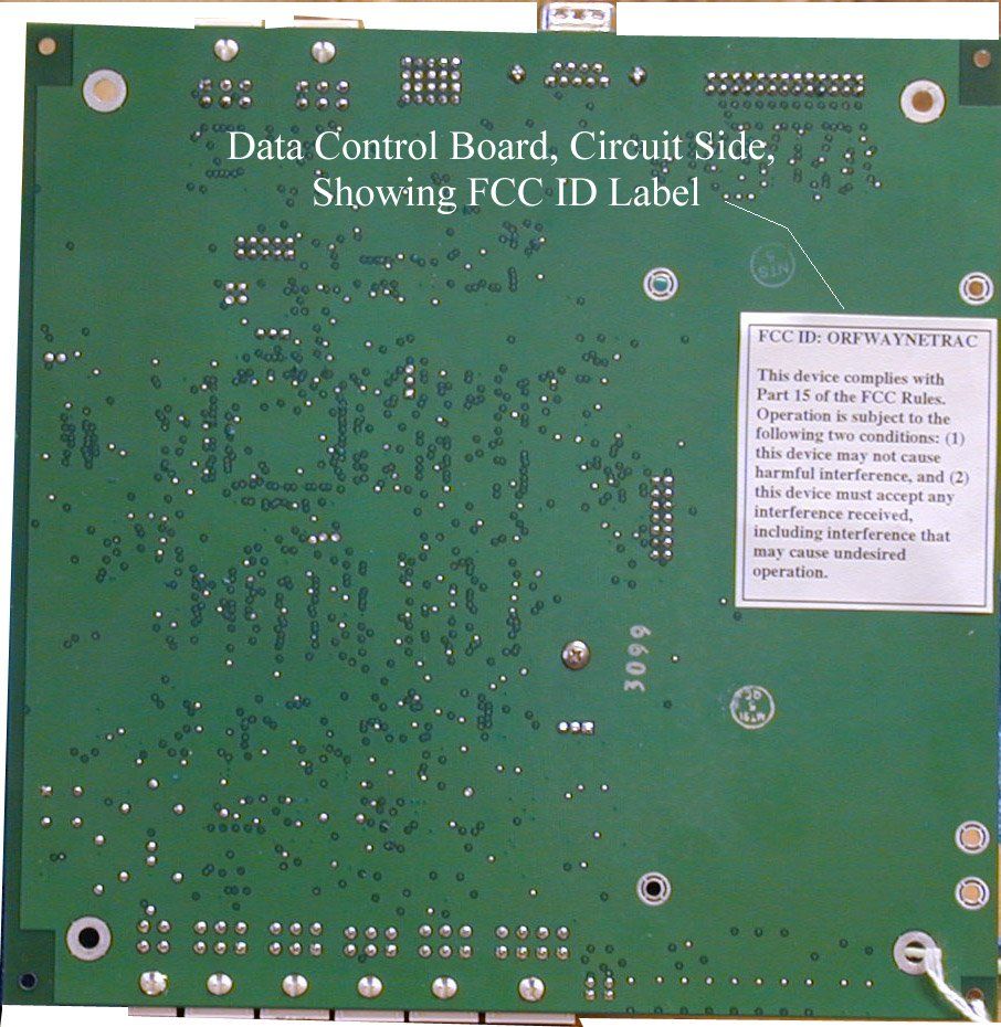
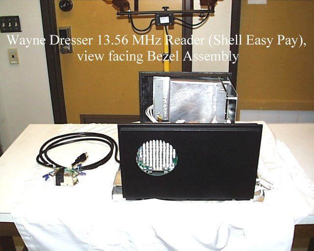
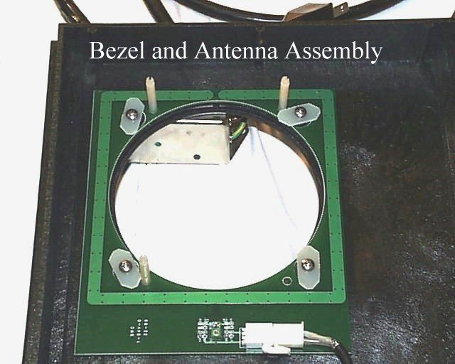
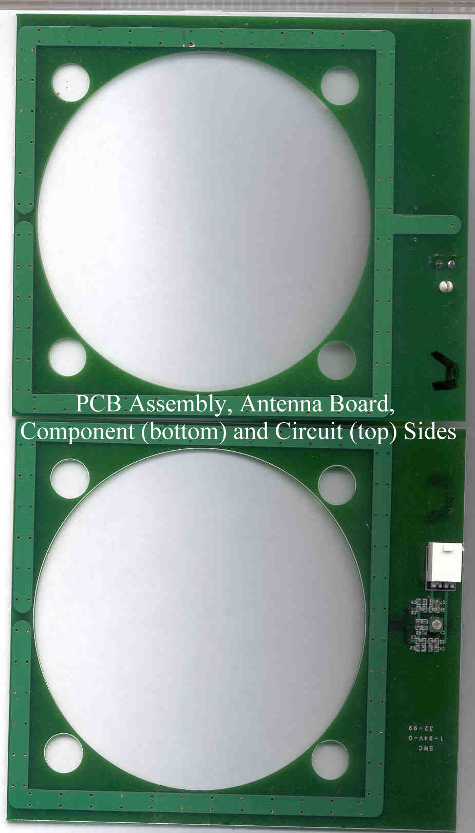
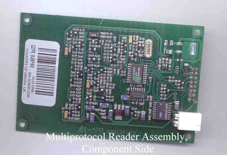
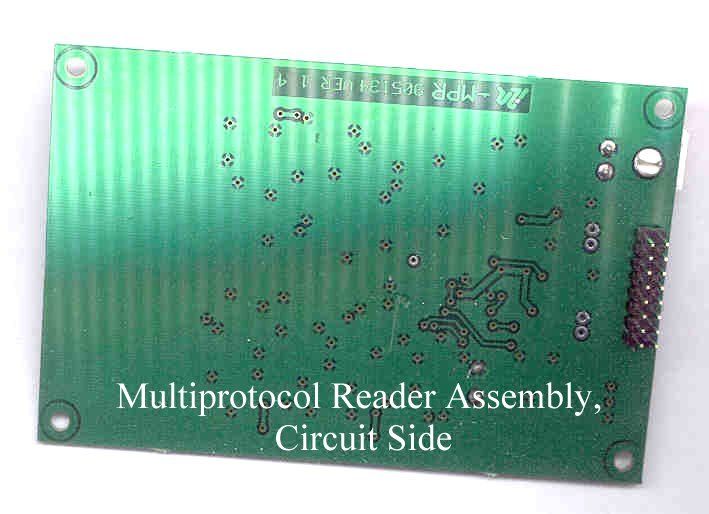
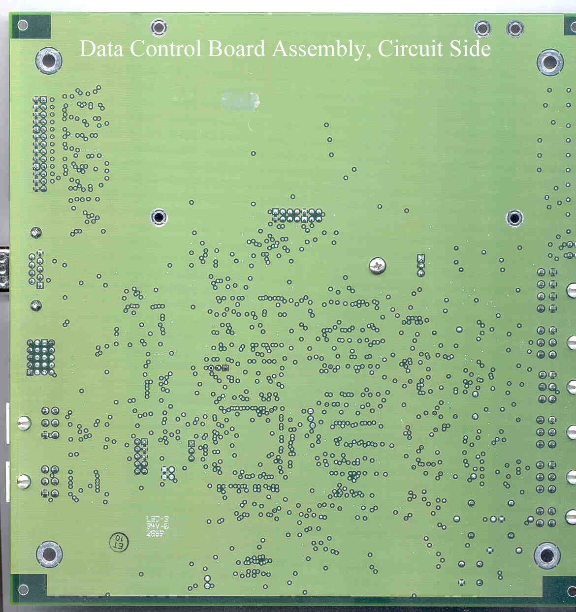
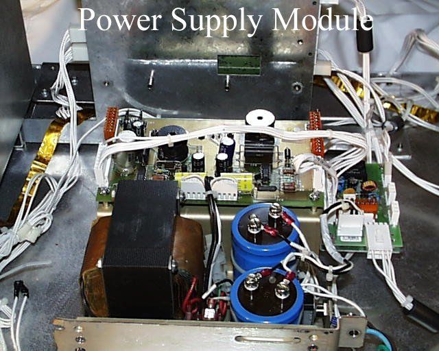
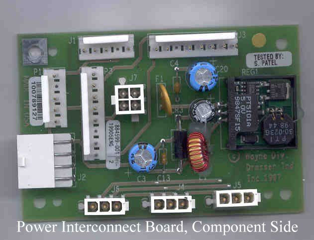
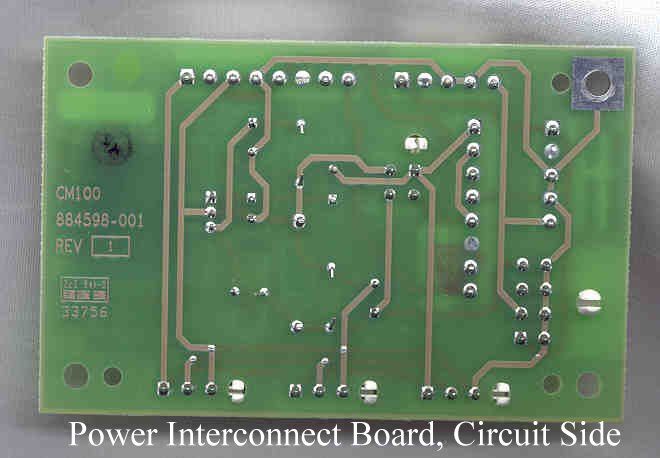
Document Text
Text extracted from the exhibit documents filed with the FCC. Open a document above to read the original.
Users Manual
INSTALLATION Wayne EasyPAY TM for Vista Dispensers Preliminary Draft Limited Distribution WAYNE LiftForReceipt Installation Manual EasyPAY TM for Vista Dispensers Copyright 1999 Dresser Industries, Inc. All rights reserved. Printed in the United States of America EasyPay is a trademark of Wayne Division/Dresser Equipment Group, a Halliburton Company. No part of this publication may be electronically or mechanically reproduced, stored in a retrieval system, or transmitted, in any form or by any means without express written permission of Dresser Industries. Translation of this material to another language without express written permission of Dresser Industries is prohibited. The information in this publication is for informational use only and is subject to change without notice. The contents should not be construed as a commitment by Dresser Industries, Inc. who assumes no responsibility or liability for in- accuracies that may appear in this publication. Wayne Division / Dresser Industries, Inc. 3814 Jarrett Way, Austin, TX 78728 Telephone: (512) 388-8311 Fax: (512) 388-8355 vii October 1999Part No. 920472 Rev. 3 (A) Table of Contents 1Before You Start Introduction 1-1 Unpacking and Inspection 1-2 Returning Damaged Components 1-2 Required Tools 1-3 Power Ratings 1-3 2Vista EasyPAY Kit Installation Introduction 2-1 Removing Dispenser Power 2-1 Removing the Bezels 2-1 Lowering the DEMs 2-3 Installing the Authorization Light Assembly (PN887124) 2-4 Relocating Wayne Vac Control Board 2-6 Installing EMI Filter2-7 Installing Power Distribution Board 2-7 Installing Power Supply Cables 2-8 Installing the DCB (PN 887123-001) in Electronic Head 2-9 Installing DCB Assembly in Electronic Heads Equipped with Printer Base PN 883727-001 2-9 Installing DCB Assembly in Electronic Heads Equipped with Printer Base PN 886208-001 2-10 Installing Cables in Electronic Head 2-12 viii Part No. 920472 Rev. 3 (A)October 1999 About This Manual Installing Power and DCB Assembly Cables 2-12 Modifying and Connecting Product Relay Cables (New Installations Only) 2-13 Addressing Lightboards2-14 Connecting Bezel Wiring and Reinstalling the Bezels 2-14 Reapplying Power 2-15 Installing Patent and Serial Number Decal 2-15 System Power-Up 2-16 3Subpump Controller Installation Introduction 3-1 Power Rating 3-1 4System Test Introduction 4-1 Light Panel Functionality Test 4-1 EasyPAY Functionality Test 4-2 AWiring Diagrams Introduction A-1 vii October 1999Part No. 920472 Rev. 3 (A) How To Use This Manual This manual explains how to install the EasyPAY™ Vista retrofit. This includes Models V390, V395, V490, and V590. Important:By following this instruction manual from chapter 1 through chapter 4 in the sequences presented, you will be assured of a successful install. For best results, do not perform the steps out of the sequence shown. Section 1 includes unpacking and inspection procedures, component return procedures, and a list of tools required to install the retrofit kit. Section 2 provides instructions for installing the EasyPAY™ hardware in the dispenser head. Section 3 explains how to install the master installation kit. Section 4 shows how to test the EasyPAY™ hardware after installation. Appendix A includes interconnection wiring diagrams for the complete installation. viii Part No. 920472 Rev. 3 (A)October 1999 About This Manual 1-1 October 1999Part No. 920472 Rev. 3 (A) Section 1 Before You Start 1.1Introduction This manual explains how to install the EasyPAY™ retrofit kit in Wayne™ Vista 90 series dispensers. This includes Models V390, V395, V490, and V590. By following this instruction manual in the sequences presented, you will be assured of a successful in- stall. For best results, perform the steps in the sequence given for the particular kit or kits that are being installed. Important:These retrofit kits require installation of several wiring and hardware assemblies. Any installation or modification must comply with the requirements of the National Electrical Code (NFPA 70), the Automotive and Marine Service Station Code (NFPA 30A) and any other applicable codes. Refer to the information in Table 1-1 for identification of the EasyPAY™ retrofit kits. 1-2 Part No. 920472 Rev. 3 (A)October 1999 Section 1: Before You Start Important:You must wear a static wrist strap, part number 916962 or equivalent, securely attached to an earth ground, when handling any circuit board, electronic component or assembly, or when reaching into the site controller or dispenser computer enclosure. Do not use power tools. 1.2Unpacking and Inspection Complete the following steps: 1.Before opening any cartons, count the number of cartons and verify the carton count against the supplied packing list. 2.Inspect the cartons for damage made during transit. 3.File claim information with the carrier on the bill of lading. 4.Retain cartons suspected of damage for future claim purposes. Caution:You must wear an anti-static wrist strap, part number 916962 when removing electronic components from static packages. Attach the wrist strap securely to an earth grounding point to prevent possible damage from static electricity. 5.Remove all equipment from the shipping cartons and carefully inspect for visible damage. Note:Any damage should be brought to the attention of the carrier and claims made immediately. Return all equipment to the respective cartons for protection until actual installation is made. Save all cartons until it is certain that return shipments are not required. 6.Check supplied graphics (such as ad panel and dial face graphics) prior to start of installation. 1.3Returning Damaged Components Parts or components returned to the factory under warranty or for repair are subject to damage if not pack- aged properly. Complete the following steps to return parts or components to the factory. 1.Place electronic components in an anti-static bag and in the original shipping cartons for return shipment to the factory. Note:If original shippin…
Text truncated - open the document above for the full version.
ID Label/Location Info
DWN BY Mo Afshar28FEB97 DESIGNER CHK BY N. DeWilde28FEB97 ENGR Mo Afshar28FEB97 ENG MGR Mo Afshar for EGV28FEB97 APPVD CONFIG MGT Carol Hall28FEB97 WAYNE DIVISIONSizeDrawing NumberSheetRev Dresser Industries Inc. Austin, Tx.A884366-XXX1of2? This document contains PROPRIETARY and CONFI- DENTIAL information and is the exclusive property of the Wayne Division of Dresser Industries, Inc. Therefore, neither the drawing nor its content are to be used, reproduced, or disclosed, in whole or in part, without the prior written permission of the Wayne Division; and this drawing and all copies of it shall return to the Wayne Division on demand TITLE: DEACL,FCC,WAYNE TRAC PART NUMBERREVDESCRIPTION 884366-005DECAL,FCC,WAYNE TRAC,EASY PAY,COMP 884366-006DECAL,FCC,WAYNE TRAC,EASY PAY,DISP NOTES: UNLESS OTHERWISE SPECIFIED 1. PRINT LABEL WITH A THERMAL PRINTER 2. REFERENCE THE LABEL, THT, SPEC (883713-001) FOR BLANK LABEL STOCK, RIBBON STOCK AND OTHER COMPATIBILITY INFORMATION AS NEEDED 3. ALL PRINTED INFORMATION IS PRINTED BY LABEL SOFTWARE. THE OPERATOR IS REQUIRED TO ENTER INFORMATION REQUESTED BY THE LABEL SOFTWARE. 4. SIZES: -001.75 X .25 -002, -004, -006 3.00 X 2.00 -003, -0052.00 X 1.5 FCC ID: ORFWAYNETRAC This device complies with Part 15 of the FCC Rules. Operation is Subject to the following two conditions: (1)this device may not cause harmful interference, and (2) this device must accept any interference received, including interferences that may cause undesired operation. -005 APPLICATIONREVISIONS NEXT ASSEMBLYMODELLTRDESCRIPTIONDATEAPPV’D WAYNE TRACACONFIG MGT REL 6MAR97LRM REDRAWN PER ECO WAYNE DIVISIONSizeDrawing NumberSheetRev Dresser Industries Inc. Austin, Tx.A884366-XXX2of2? FCC ID: ORFWAYNETRAC This equipment contains an Intentional Radiator approved by the FCC under the FCC ID number shown above. This device complies with Part 15 of the FCC Rules. Operation is Subject to the following two conditions: (1) this device may not cause harmful interference, and (2) this device must accept any interference received, including interferences that may cause undesired operation. -006
ID Label/Location Info
2-12 Part No. 920473 Rev. 2 (A)October 1999 Section 2: DL EasyPAY Kit Installation 15. Replace any advertisement devices you may have removed. 2.12Reapplying Power 1.Reapply power to dispenser and refer to the test instructions in Chapter 4 and the service manual "System Tests for Dispenser Electronics" (PN 920353). 2.13Installing Patent and Serial Number Decal Refer to Figure 2-12 for the following steps: 1.Remove EasyPAY serial number and FCC decals from kit. 2.Locate the Dispenser ID plate on the lower left corner of side 1 on the chassis frame. 3.Clean area of dirt and oil before you apply decals. 4.Affix decals securely onto dispenser adjacent to existing ID plate. Figure 2-12 Dispenser Decal Location Model ID Plate CID Serial No. Decal FCC Decal EZPay
ID Label/Location Info
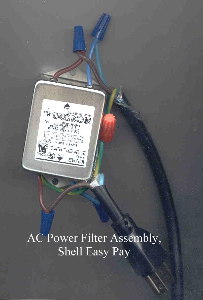
2-8 Part No. 920472 Rev. 3 (A)October 1999 Section 2: Vista EasyPAY Kit Installation Figure 2-7 Installing the Power Distribution Board (PDB) 4.Return the power supply to the operation position after PDB is in place. 2.8.1Installing Power Supply Cables 1.Connect cable PN 880586-001 to P1 on PDB. 2.Connect P3 of cable PN 881984-002 to P3 on PDB. 3.Connect cable PN 886011-001 from J1 on PDB to J1 on power supply board. 4.Connect cable PN 886005-001 from J3 on the PDB to J3 on the power supply board. 2.9Installing the DCB (PN 887123-001) in Electronic Head Important:Before installing the DCB in the Vista dispenser, you must first identify the printer base. If the dispenser is equipped with printer base PN 883727-001, then you equip the dispenser with the EasyPAY assembly PN 887123-001shown in Figure 2-8. If the dispenser is equipped with a printer base PN 886208-001 then you must modify the assembly. To do so, refer to 2.9.2. Power Supply Board Side 2 DEM instpdb.cdr Power Distribution Board Section 2: Vista EasyPAY Kit Installation 2-9 October 1999Part No. 920472 Rev. 3 (A) 2.9.1Installing DCB Assembly in Electronic Heads Equipped with Printer Base PN 883727-001 If you are installing the DCB in a Vista with the "old" printer base PN 883727-001, refer to Figure 2-8. Figure 2-8 EasyPAY Assembly for Use With Old Printer Base PN 883727-001 1.If there are any ground wires attached to the lower DCPT frame, be sure to disconnect them before installing the DCB assembly. Once the DCB is in place, then reconnect. 2.Install the new DCB assembly such that it is facing the heater fan.
Test Report
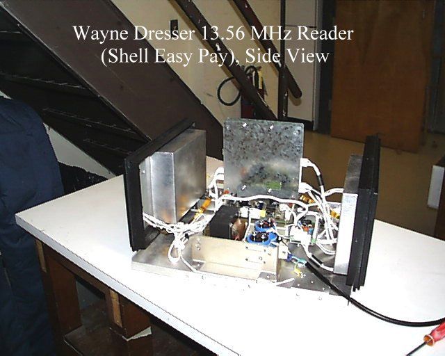
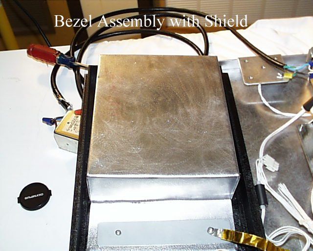
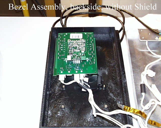
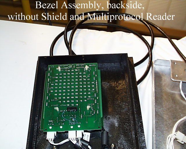
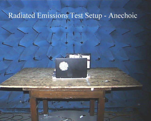
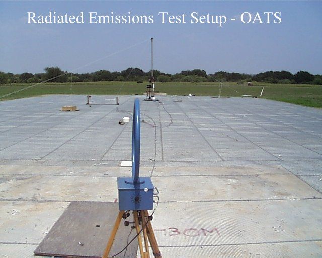
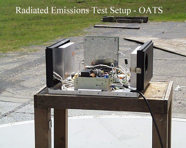
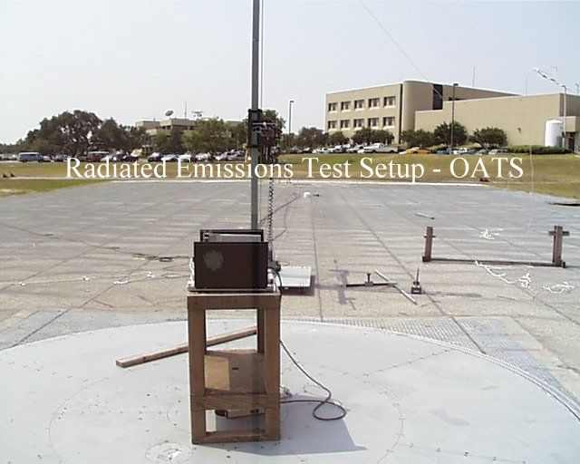
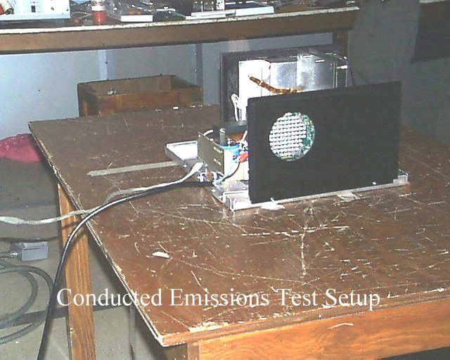
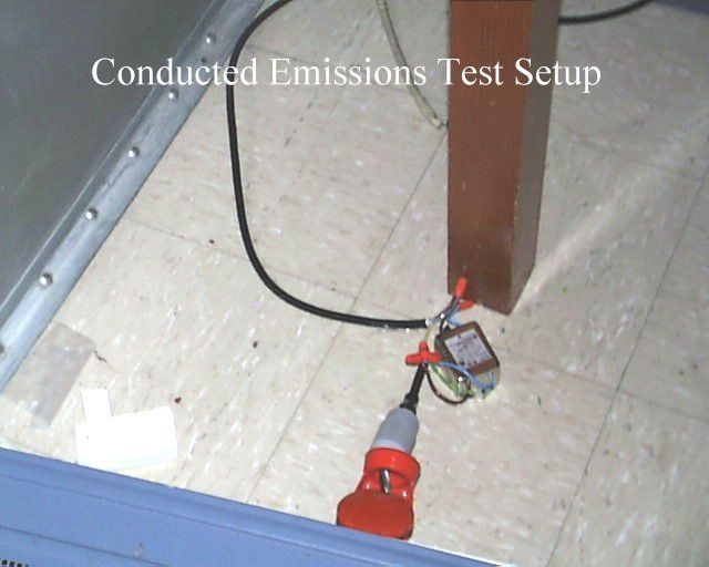
FCC ID: ORFWAYNETRAC 1 of 29 MEASUREMENT AND TECHNICAL REPORT ON THE WAYNE DRESSER 13.56 MHz READER Southwest Research Institute 6220 Culebra Road San Antonio, Texas 78228-0510 Project 10-3169-003 Report Number EMCR 99/117 Prepared for: Wayne Dresser 3814 Jarrett Way Austin, Texas Prepared by: David A. Carmony October 1999 Reviewed by:Approved by: _____________________________________________________________________________ Ismael Martinez, Jr.James J. Polonis Senior Engineering TechnologistManager Electromagnetic Compatibility Research SectionElectromagnetic Compatibility Research Section Communications Engineering DepartmentCommunications Engineering Department FCC ID: ORFWAYNETRAC 2 of 29 FCC ID: ORFWAYNETRAC 3 of 29 TABLE OF CONTENTS Page List of Tables ............................................................................................................................................... 3 1.0General Information ........................................................................................................................ 4 1.1Product Description......................................................................................................................... 4 1.2Related Grants................................................................................................................................. 4 1.3Tested System Details ..................................................................................................................... 4 1.4Test Methodology ........................................................................................................................... 5 1.5Test Facility..................................................................................................................................... 5 2.0Product Labeling ............................................................................................................................. 6 2.1FCC ID Label .................................................................................................................................. 6 2.2Location of Label on EUT .............................................................................................................. 6 2.3Label for the Exterior of Devices Incorporating the EUT .............................................................. 6 2.4Supplemental Information to be in the Reader Manual .................................................................. 6 3.0System Test Configuration.............................................................................................................. 7 3.1Justification ..................................................................................................................................... 7 3.2EUT Exercise ................................................................................................................................. 7 3.3Special Accessories......................................................................................................................... 7 3.4Equipment Modification ................................................................................................................. 7 3.5 Configuration of Tested System ..................................................................................................... 7 3.6Antenna System .............................................................................................................................. 7 4.0Block Diagram of the 13.56 MHz Reader........................................................................................8 5.0Conducted and Radiated Measurement Photos..................................................................... ........ 9 6.0Conducted Emission Data ............................................................................................................. 10 6.1Conducted Measurement Data ...................................................................................................... 10 6.2Conducted Test Instrumentation ................................................................................................... 10 7.0Radiated Emission Data ................................................................................................................ 11 7.1Radiated Measurement Data ......................................................................................................... 11 7.2Test Instrumentation for Radiated Measurements ........................................................................ 15 7.3Field Strength Calculation ............................................................................................................ 15 Appendix A: Conducted Emissions Measurement Plots ........................................................................... 16 Appendix B: Radiated Signature Measurement Plots................................................................................ 19 Appendix C: Test Instrumentation ............................................................................................................. 25 Appendix D: Photos of Tested EUT .......................................................................................................... 27 Appendix E: Photos of Test Setups............................................................................................................ 28 Attachment 1: Functional Description and Block Diagram Attachment 2: Installation Instructions Attachment 3: FCC ID Label Attachment 4: Schematics FCC ID: ORFWAYNETRAC 4 of 29 LIST OF TABLES TablePage 1.1System Components ......................................................................................................................... 4 6.1Worst Case Conducted Emission Levels ....................................................................................... 10 7.1Measurements of Fundamental Frequency .......................................................................…
Text truncated - open the document above for the full version.
Contact Information
Applicant
Phil Katselnik(Lead Regulatory Engineer)
Technical Contact
Wayne Division, Dresser Equipment Group, IncLennie Reeh
[email protected]512-388-8326
3814 Jarrett Way · Austin, Texas · United States
Test Firm
Southwest Research InstituteDavid Carmony
210-684-5111
Technical Specifications
| # | Rule Parts | Frequency Range | Power Output |
|---|---|---|---|
| 1 | 15C | 13.56 MHz - 13.56 MHz | - |
Other Applications from Wayne Fueling Systems LLC

ORF-VISTA
Jun 04, 2006RF ID Tag Reader
Equipment Class
DXX - Part 15 Low Power Communication Device Transmitter
ORF-OVATION
May 29, 2006RF ID Tag Reader
Equipment Class
DXX - Part 15 Low Power Communication Device Transmitter
ORFWAYNETRACII
Feb 28, 2001DXX - Part 15 Low Power Communication Device Transmitter
Equipment Class
DXX - Part 15 Low Power Communication Device Transmitter