ORFWAYNETRACII
Wayne Fueling Systems LLC
Click to zoom
Application Details
- Equipment Class
- DXX - Part 15 Low Power Communication Device Transmitter
- Date of Grant
- Feb 28, 2001
- Application Purpose
- Original Equipment
- Date of Application
- Jun 28, 2000
- Frequency Range
- 13.56000000 - 13.56000000
- Company
- Wayne Fueling Systems LLC
- Country
- United States
Documents & Files
Document Text
Text extracted from the exhibit documents filed with the FCC. Open a document above to read the original.
Users Manual
1-1 July 2000Part No. 920472 Rev. C Section 1 Before You Start 1.1Introduction This manual explains how to install the EasyPAY™ retrofit kit in selected models of Wayne™ Vista 90 series dispensers. This includes all Models V390, V395, V490 and V590 except those with 2/ and 3/ prefix numbers. By following this instruction manual in the sequences presented, you will be assured of a successful in- stall. For best results, perform the steps in the sequence given for the particular kit or kits that are being installed. Important:These retrofit kits require installation of several wiring and hardware assemblies. Any installation or modification must comply with the requirements of the National Electrical Code (NFPA 70), the Automotive and Marine Service Station Code (NFPA 30A) and any other applicable codes. Refer to the information in Table 1-1 for identification of the EasyPAY™ retrofit kits. 1-2 Part No. 920472 Rev. CJuly 2000 Section 1: Before You Start Important:You must wear a static wrist strap, part number 916962 or equivalent, securely attached to an earth ground, when handling any circuit board, electronic component or assembly, or when reaching into the site controller or dispenser computer enclosure. Do not use power tools. No Modifications:Modifications to this device shall not be made without the written consent of Wayne Division, Dresser Equipment Group. Unauthorized modifications may void the authority granted under Federal Communications Commission Rules permitting the operation of this device. 1.2Unpacking and Inspection Complete the following steps: 1.Before opening any cartons, count the number of cartons and verify the carton count against the supplied packing list. 2.Inspect the cartons for damage made during transit. 3.File claim information with the carrier on the bill of lading. 4.Retain cartons suspected of damage for future claim purposes. Caution:You must wear an anti-static wrist strap, part number 916962 when removing electronic components from static packages. Attach the wrist strap securely to an earth grounding point to prevent possible damage from static electricity. 5.Remove all equipment from the shipping cartons and carefully inspect for visible damage. Note:Any damage should be brought to the attention of the carrier and claims made immediately. Return all equipment to the respective cartons for protection until actual installation is made. Save all cartons until it is certain that return shipments are not required. 6.Check supplied graphics (such as ad panel and dial face graphics) prior to start of installation. 1.3Returning Damaged Components Parts or components returned to the factory under warranty or for repair are subject to damage if not pack- aged properly. Complete the following steps to return parts or components to the factory. 1.Place electronic components in an anti-static bag and in the original shipping cartons for return shipment to the factory. Note:If original shipping cartons are not available use a sturdy cardboard container and suitable packing materials such as anti-static polyethylene foam or bubble pack, to ensure the component is firmly packed. 2.Include a Return Parts Tag with the defective component describing the particular problem with the part. Table 1-1 EasyPAY™ Retrofit Kits for Vista Part NumberDescription 887122-001EasyPAY Retrofit Kit, Vista DS Section 1: Before You Start 1-3 July 2000Part No. 920472 Rev. C 3.Make sure adequate insurance is provided when returning parts to the factory. WARNING:If the parts or components arrive at our factory in a damaged condition and it is determined that the damage is a direct result of inadequate or improper packaging, the damage will not be covered under the original warranty and the customer or distributor will be held responsible for the cost of repairs necessary to correct or replace the damaged parts. 1.4Required Tools Refer to Table 1-2 for a list of tools required to install the EasyPAY retrofit kit. 1.5Power Ratings The EasyPAY installation does not change the existing dispenser power rating. Table 1-2 Required Tools QuantityDescription 1Phillips Screwdriver (medium and small) 1Slotted Screwdriver (medium and small) 11/4 inch Nut Driver 13/8 inch Socket Wrench 1Diagonal Cutters 1Anti-static Wrist Strap 1Wire Stripper 1Needle Nose Pliers 1Pin Pusher 1-4 Part No. 920472 Rev. CJuly 2000 Section 1: Before You Start
Users Manual
2-1 July 2000Part No. 920472 Rev. C Section 2 Vista EasyPAY Kit Installation 2.1Introduction The information in this chapter explains how to install the EasyPAY retrofit kit (PN 887122-001). Note:It is necessary to identify Side 1 and Side 2 of the dispenser in order to carry out the instructions that follow. Note that the dispenser ID plate is located on the lower left corner of the chassis frame on Side 1. See Figure 2-16 for illustration. 2.2Removing Dispenser Power Before you begin installing the retrofit kit, perform the following steps to protect the kit assemblies from damage. 1.Close station to fuel purchases. 2.Disconnect the power from dispensers at the power panel. Post a warning sign at the power panel stating that the equipment is being serviced. 2-2 Part No. 920472 Rev. CJuly 2000 Section 2: Vista EasyPAY Kit Installation 2.3Removing the Bezels Complete the following steps to remove the bezels from the dispenser. 1.Remove and save any temporary advertisement or instructional attachments from the bezel face. 2.Place an anti-static wrist strap (PN 916962 or equivalent) on your wrist and attach the other end of the wrist strap to an earth grounding point. 3.Disengage the advertisement (ad) panels. Unsnap the ad panel by pulling forward firmly on the top edge of the panel. Refer to Figure 2-1. Figure 2-1 Removing the Ad Panel 4.If necessary, unlock the function switch door. 5.Turn the wing fasteners on the left and right side of bezel counter clockwise. Refer to Figure 2-2. WAYNE Wayne 11 1 23 2 3 Tilt the ad panel out and down toward you. 1/4 Turn Phillips Head Screws Ad Panel Blank Panel DJR-FH/CD-1302A Lift For Receipt Lift For Receipt Section 2: Vista EasyPAY Kit Installation 2-3 July 2000Part No. 920472 Rev. C Figure 2-2 Wing Fasteners on Bezel 6.Rest the lower edge of the bezel on the dispenser and disconnect the following cables from the back of the bezel. a.If the bezel is equipped with a graphic display, disconnect the graphic display heater cable (PN 882827-001) plugged in the 2-conductor black connector that routes on the right side of the graphic display. See Figure 2-3. Figure 2-3 Disconnecting Cables on Back of Graphic Display Bezel b.Disconnect the cable assembly (PN 881524-001) installed in J5 on the annunciator interface board. Refer to Figure 2-3 and Figure 2-4 for the following steps. c.If the bezel is equipped with a Push-to-Start (PTS) bar, disconnect the cable assembly (PN 881692-01 or 881693-01) plugged in the 13-pin connector on the back of the bezel. d.If the bezel is equipped with a CPM and a DES keypad, disconnect the cable assembly (PN 880963-02) plugged in the 4-pin connector on the DES keypad cable. e.If the bezel is equipped with KDC and a DES keypad is present, disconnect the cable assembly (PN 880963-01) plugged in the 4-pin DES keypad cable. WAYNE 2 2 1 1 3 3 4 4 3 2 PTS Bar Area Ad Panel (lowered) Ad Panel Fasteners Wing FastenersFunction Switch Door Lock DJR-CD-1303A Lift For Receipt Rear View of CPM Bezel J3 JP1 J5 DJR-FH/CD-1304A Graphic Display Adapter Board (Part No. 882440-xxx) DES Keypad 4-Pin DES Keypad Cable Vista Annunciator Interface Board (Part No. 883074-xx) 2-4 Part No. 920472 Rev. CJuly 2000 Section 2: Vista EasyPAY Kit Installation f.Repeat steps 3 through 6 to remove the bezel on the other side of the dispenser. 2.4Lowering the DEMs Perform the following steps to lower the DEM(s) (Display Electronic Modules) to the service position. 1.Use a slotted screwdriver to loosen two ¼ turn screws located at the top of the DEM. Refer to Figure 2-5. 2.Lower the DEM to the service position. 3.Repeat steps 1 and 2 for the DEM on the other side of the dispenser. Figure 2-4 Disconnecting Cables on Bezel Back DJR-FH/CD-1107A Rear View of KDC Bezel Rear View of CPM Bezel J4 J2 J5 J9J3 Captive Screw (5 Places) Rain Catcher J1 J10 Display Board Display Bracket Mounting Screw (4 Places) J4 on Annunciator Interface Board (Part No. 880869-xx) J4 J5 J2 J1 Display Bracket Mounting Screw (4 Places) Display Board Annunciator Interface Board (Part No. 881182-xx or 883072-xx) Section 2: Vista EasyPAY Kit Installation 2-5 July 2000Part No. 920472 Rev. C Figure 2-5 Lowering the DEM into the Service Position 2.5Installing the Authorization Light Assembly (PN887124) Complete the following steps to remove the blank panel from the bezel and install the authorization light assembly (PN 887124-001) in its place. Refer to Figure 2-6. 1.Locate the side 1 bezel removed earlier in paragraph 2.3. 2.Use a ¼ inch nut driver to loosen and remove 3 hex head screws securing the blank panel to the back of the bezel. (See the following figure.) Set the blank panel aside. Retain the hardware for reinstallation later. Note:Examine bezel opening to determine that all material from the old gasket has been removed. DEM 1/4 Screws (2 Places) Dispenser Front View Side 1 DEM Service Position Dispenser Side View DJR-FH/CD-1321A 2-6 Part No. 920472 Rev. CJuly 2000 Section 2: Vista EasyPAY Kit Installation Figure 2-6 Removing the Blank Panels from the Vista Bezel 3.Remove an authorization light assembly (PN 887124-001) from the retrofit kit and examine it to determine if the gasket is in place. 4.With the back of the authorization light panel facing toward you, install the device in the bezel. See Figure 2-7. Blank Panel Back View of Bezel Receiving Slots (3 Places) Mounting Hardware (3 Places) Back View of Bezel Mounting Hardware (3 Places) Receiving Slots (3 Places) Removing the Blank Panel from the VistaCard Bezel Removing the Cash Access Door Panel from the VistaPay Bezel vistabks.cdr Section 2: Vista EasyPAY Kit Installation 2-7 July 2000Part No. 920472 Rev. C Figure 2-7 Installing the Authorization Light Panel (PN 887124-001) 5.Secure the authorization light bezel assembly to the bezel using the mounting hardware set aside in Step 2. Use a ¼ inch nut driver to tighten the hardware. 6.Install authorization side 2 light assembly PN 887124-001 by repeating steps 1 through 5 for the…
Text truncated - open the document above for the full version.
Cover Letter(s)
www.wayne.com WAYNE DIVISION DRESSER EQUIPM ENT GROUP, INC. 3814 Jarrett Way • •• • Austin, TX 78728-1212 • •• • Phone 512-388-8311 • •• • Fax 512-388-8302 A Halliburton Company Federal Communications Commission Equipment Approval Services P.O. Box 358315 Pittsburgh PA 15251-5315 Dear Sirs; Enclosed is a completed Form 159, along with payment, for FCC compliance submittal referenced by FCC ID: ORFWAYNETRACII, conformation # EA98055. It is requested that confidentiality be maintained for all schematics, block diagrams and operational descriptions. Thank you, Lennie Reeh Senior Staff Engineer
Cover Letter(s)
July 12, 2000 TO:FCC FROM:Lennie Reeh, Wayne Division, Dresser Equipment Group, Inc. SUBJECT: Request for Modular Approval A submission for certification was made for Part 15 intentional radiator FCC ID number ORFWAYNETRACII (Form 731 confirmation number EA98055) on June 29, 2000. Today, July 11, 2000, we received Public Notice DA 00-1407, dated June 26, 2000, which states that Part 15 unlicensed modular transmitter approval may only be obtained by request via a cover letter. By this letter, we hereby request modular approval for Part 15 intentional radiator ORFWAYNETRACII. The following items address the eight requirements specified in Public Notice DA 00-1407. 1. Intentional radiator ORFWAYNETRACII has its own RF shielding and, therefore, does not depend upon an external device to provide additional shielding to meet Part 15 requirements. 2. Intentional radiator ORFWAYNETRACII does not have any modulation/data inputs. 3. Intentional radiator ORFWAYNETRACII has its own power supply regulation. 4. The antenna of intentional radiator ORFWAYNETRACII is a printed circuit board antenna and connects to the transmitter output stage via a Tyco (Amp) p/n 172165-1 Mini-Mate-N-Lock plug and a Tyco (Amp) p/n 770966-2 Mini-Mate-N-Lock PCB-mount receptacle. These are non-standard connectors. 5. Intentional radiator ORFWAYNETRACII was tested in a stand-alone configuration. It met the requirements of Section 15.207. 6. Intentional radiator ORFWAYNETRACII will be labeled with its own FCC ID. A separate label will also be provided for display on the outside of the device into which it is installed. These labels can be viewed on the FCC web site under “FCC ID Labels.” 7. Intentional radiator ORFWAYNETRACII meets the requirements of Section 15.225. No special instructions are required to insure the intentional radiator continues to comply with the FCC rules other than the statement that modifications may not be made to this device “without the written consent of Wayne Dresser. Unauthorized modifications may void the authority granted under Federal Communications Commission Rules permitting the operation of this device”. This statement is located in the installation manual. 8. No special RF exposure requirements are specified for the intentional radiator ORFWAYNETRACII. DAC
Cover Letter(s)
ORFWAYNETRACII – Confidentiality Letter 13536 North Central Expressway, MS 457, Dallas, TX 75243 _____________________________________________________ October 19, 2000 Via Electronic Filing Federal Communications Commission EQUIPMENT APPROVAL SERVICES P.O. Box 358315 Pittsburgh, PA 15251-5315 Re:FCC ID No.: ORFWAYNETRACII Confirmation Number: EA98055 Correspondence Reference Number: 16289 Dear Sir or Ma’am: Pursuant to 47 C.F.R. § 0.459, Texas Instruments respectfully requests confidential protection of the following documents submitted electronically in furtherance of the above-reference application for Dresser Industries Inc. as containing proprietary information listed below: FCC Confidentiality • Electrical Schematics for Multiprotocol Reader Board RI-STU-TRDB-XX. (RISTUTRDBsch.pdf, Adobe Acrobat files *.pdf, 32 pages total) The reason for request for confidentiality is that these documents contain Texas Instruments proprietary and internal information and it is critical from a product technology and know-how standpoint (hardware and software) that this information remains confidentia l. Should you have any questions regarding the matters addressed herein, please do not hesitate to contact me at (972) 575-2484 ([email protected]). Respectfully submitted, By:/s/ V. C. Kumar V. C. Kumar Programs Manager
Cover Letter(s)
ORFWAYNETRACII – Confidentiality Letter 13536 North Central Expressway, MS 457, Dallas, TX 75243 _____________________________________________________ October 19, 2000 Via Electronic Filing Federal Communications Commission EQUIPMENT APPROVAL SERVICES P.O. Box 358315 Pittsburgh, PA 15251-5315 Re:FCC ID No.: ORFWAYNETRACII Confirmation Number: EA98055 Correspondence Reference Number: 16289 Dear Sir or Ma’am: Pursuant to 47 C.F.R. § 0.459, Texas Instruments respectfully requests confidential protection of the following documents submitted electronically in furtherance of the above-reference application for Dresser Industries Inc. as containing proprietary information listed below: FCC Confidentiality • Electrical Schematics for Multiprotocol Reader Board RI-STU-TRDB-XX. (RISTUTRDBsch.pdf, Adobe Acrobat files *.pdf, 32 pages total) The reason for request for confidentiality is that these documents contain Texas Instruments proprietary and internal information and it is critical from a product technology and know-how standpoint (hardware and software) that this information remains confidentia l. Should you have any questions regarding the matters addressed herein, please do not hesitate to contact me at (972) 575-2484 ([email protected]). Respectfully submitted, By:/s/ V. C. Kumar V. C. Kumar Programs Manager
ID Label/Location Info
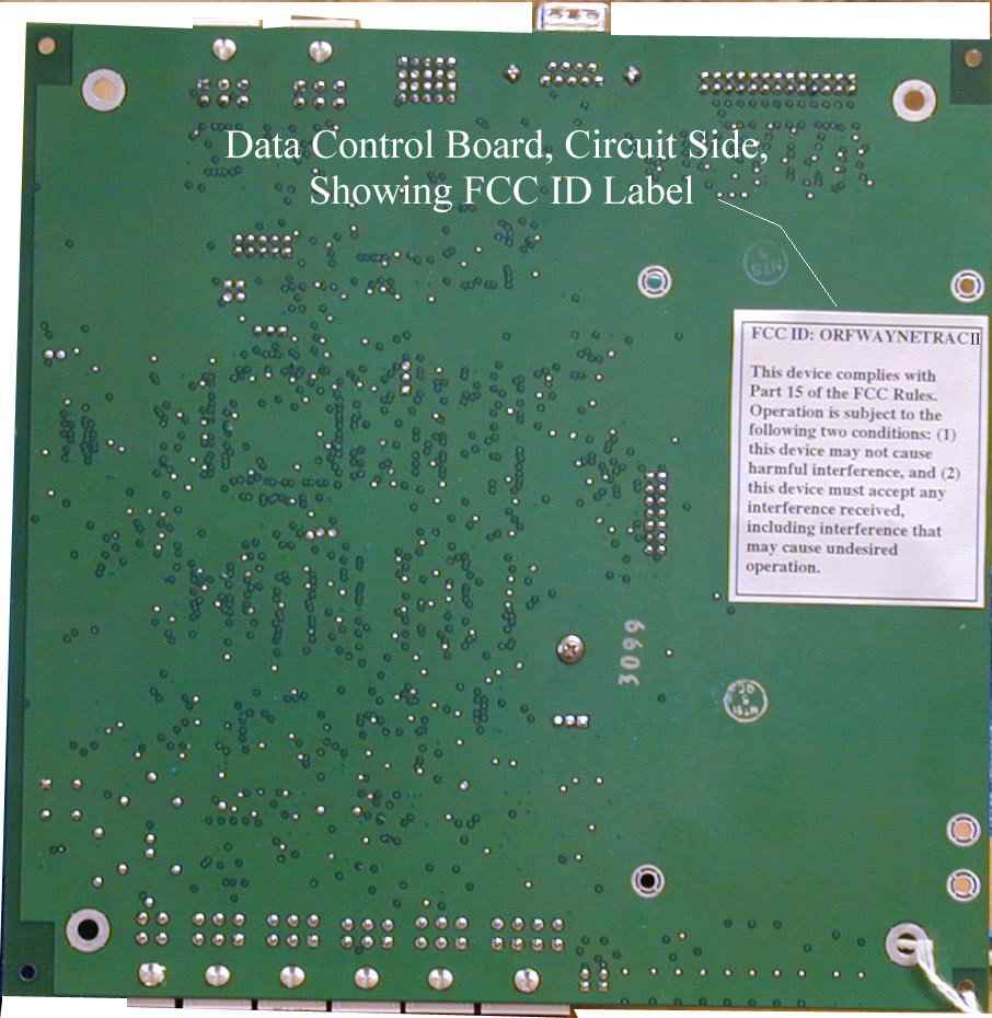
DWN BY Mo Afshar28FEB97 DESIGNER CHK BY N. DeWilde28FEB97 ENGR Mo Afshar28FEB97 ENG MGR Mo Afshar for EGV 28FEB97 APPVD CONFIG Carol Hall28FEB97 WAYNE DIVISIONSizeDrawing NumberSheetRev Dresser Industries Inc. Austin, Tx.A884366-XXX1of2E This document contains PROPRIETARY and CONFI- DENTIAL information and is the exclusive property of the Wayne Division of Dresser Industries, Inc. Therefore, neither the drawing nor its content are to be used, reproduced, or disclosed, in whole or in part, without the prior written permission of the Wayne Division; and this drawing and all copies of it shall return to the Wayne Division on demand TITLE: DECAL,FCC,WAYNE TRAC PART NUMBERREVDESCRIPTION 884366-007DECAL,FCC,WAYNE TRAC,TRAC II,COMP 884366-008DECAL,FCC,WAYNE TRAC,TRAC II,DISP NOTES: UNLESS OTHERWISE SPECIFIED: 1. PRINT LABEL WITH A THERMAL PRINTER 2. REFERENCE THE LABEL, THT, SPEC (883713-001) FOR BLANK LABEL STOCK, RIBBON STOCK AND OTHER COMPAT ABILIT Y INFORMAT ION AS NEEDED 3. ALL PRINTED INFORMATION IS PRINTED BY LABEL SOFTWARE. THE OPERATOR IS REQUIRED TO ENTER INFORMATION REQUESTED BY THE LABEL SOFTWARE. 4. SIZES: -0083.00 X 2.00 -0072.00 X 1.5 FCC ID: ORFWAYNETRACII This device complies with Part 15 of the FCC Rules. Operation is subject to the following two conditions: (1) this device may not cause harmful interference, and (2) this device must accept any interference received, including interferences that may cause undesired operation. -007 APPLICATIONREVISIONS NEXT ASSEMBLYMODELLTRDESCRIPTIONDATEAPPV’D WAYNE TRAC ACONFIG MTG REL6MAR97LRM EREDRAWN PER ECO 13126 CCH 19JUN00 WAYNE DIVISION SizeDrawing NumberSheetRev Dresser Industries Inc. Austin, Tx. A884366-XXX2of2E FCC ID: ORFWAYNETRACII This equipment contains an intentional radiator approved by the FCC under the FCC ID number shown above. This device complies with Part 15 of the FCC Rules. Operation is subject to the following two conditions: (1) this device may not cause harmful interference, and (2) this device must accept any interference received, including interferences that may cause undesired operation. -008
ID Label/Location Info
2-12 Part No. 920473 Rev. 2 (A)October 1999 Section 2: DL EasyPAY Kit Installation 15. Replace any advertisement devices you may have removed. 2.12Reapplying Power 1.Reapply power to dispenser and refer to the test instructions in Chapter 4 and the service manual "System Tests for Dispenser Electronics" (PN 920353). 2.13Installing Patent and Serial Number Decal Refer to Figure 2-12 for the following steps: 1.Remove EasyPAY serial number and FCC decals from kit. 2.Locate the Dispenser ID plate on the lower left corner of side 1 on the chassis frame. 3.Clean area of dirt and oil before you apply decals. 4.Affix decals securely onto dispenser adjacent to existing ID plate. Figure 2-12 Dispenser Decal Location Model ID Plate CID Serial No. Decal FCC Decal EZPay
ID Label/Location Info
2-8 Part No. 920472 Rev. 3 (A)October 1999 Section 2: Vista EasyPAY Kit Installation Figure 2-7 Installing the Power Distribution Board (PDB) 4.Return the power supply to the operation position after PDB is in place. 2.8.1Installing Power Supply Cables 1.Connect cable PN 880586-001 to P1 on PDB. 2.Connect P3 of cable PN 881984-002 to P3 on PDB. 3.Connect cable PN 886011-001 from J1 on PDB to J1 on power supply board. 4.Connect cable PN 886005-001 from J3 on the PDB to J3 on the power supply board. 2.9Installing the DCB (PN 887123-001) in Electronic Head Important:Before installing the DCB in the Vista dispenser, you must first identify the printer base. If the dispenser is equipped with printer base PN 883727-001, then you equip the dispenser with the EasyPAY assembly PN 887123-001shown in Figure 2-8. If the dispenser is equipped with a printer base PN 886208-001 then you must modify the assembly. To do so, refer to 2.9.2. Power Supply Board Side 2 DEM instpdb.cdr Power Distribution Board Section 2: Vista EasyPAY Kit Installation 2-9 October 1999Part No. 920472 Rev. 3 (A) 2.9.1Installing DCB Assembly in Electronic Heads Equipped with Printer Base PN 883727-001 If you are installing the DCB in a Vista with the "old" printer base PN 883727-001, refer to Figure 2-8. Figure 2-8 EasyPAY Assembly for Use With Old Printer Base PN 883727-001 1.If there are any ground wires attached to the lower DCPT frame, be sure to disconnect them before installing the DCB assembly. Once the DCB is in place, then reconnect. 2.Install the new DCB assembly such that it is facing the heater fan.
Parts List/Tune Up Info
INSTALLATION Wayne EasyPAY TM for Vista Dispensers Preliminary Draft Limited Distribution WAYNE LiftForReceipt Installation Manual EasyPAY TM for Vista Dispensers Copyright 1999 Dresser Industries, Inc. All rights reserved. Printed in the United States of America EasyPay is a trademark of Wayne Division/Dresser Equipment Group, a Halliburton Company. No part of this publication may be electronically or mechanically reproduced, stored in a retrieval system, or transmitted, in any form or by any means without express written permission of Dresser Industries. Translation of this material to another language without express written permission of Dresser Industries is prohibited. The information in this publication is for informational use only and is subject to change without notice. The contents should not be construed as a commitment by Dresser Industries, Inc. who assumes no responsibility or liability for in- accuracies that may appear in this publication. Wayne Division / Dresser Industries, Inc. 3814 Jarrett Way, Austin, TX 78728 Telephone: (512) 388-8311 Fax: (512) 388-8355 vii October 1999Part No. 920472 Rev. 3 (A) Table of Contents 1Before You Start Introduction 1-1 Unpacking and Inspection 1-2 Returning Damaged Components 1-2 Required Tools 1-3 Power Ratings 1-3 2Vista EasyPAY Kit Installation Introduction 2-1 Removing Dispenser Power 2-1 Removing the Bezels 2-1 Lowering the DEMs 2-3 Installing the Authorization Light Assembly (PN887124) 2-4 Relocating Wayne Vac Control Board 2-6 Installing EMI Filter2-7 Installing Power Distribution Board 2-7 Installing Power Supply Cables 2-8 Installing the DCB (PN 887123-001) in Electronic Head 2-9 Installing DCB Assembly in Electronic Heads Equipped with Printer Base PN 883727-001 2-9 Installing DCB Assembly in Electronic Heads Equipped with Printer Base PN 886208-001 2-10 Installing Cables in Electronic Head 2-12 viii Part No. 920472 Rev. 3 (A)October 1999 About This Manual Installing Power and DCB Assembly Cables 2-12 Modifying and Connecting Product Relay Cables (New Installations Only) 2-13 Addressing Lightboards2-14 Connecting Bezel Wiring and Reinstalling the Bezels 2-14 Reapplying Power 2-15 Installing Patent and Serial Number Decal 2-15 System Power-Up 2-16 3Subpump Controller Installation Introduction 3-1 Power Rating 3-1 4System Test Introduction 4-1 Light Panel Functionality Test 4-1 EasyPAY Functionality Test 4-2 AWiring Diagrams Introduction A-1 vii October 1999Part No. 920472 Rev. 3 (A) How To Use This Manual This manual explains how to install the EasyPAY™ Vista retrofit. This includes Models V390, V395, V490, and V590. Important:By following this instruction manual from chapter 1 through chapter 4 in the sequences presented, you will be assured of a successful install. For best results, do not perform the steps out of the sequence shown. Section 1 includes unpacking and inspection procedures, component return procedures, and a list of tools required to install the retrofit kit. Section 2 provides instructions for installing the EasyPAY™ hardware in the dispenser head. Section 3 explains how to install the master installation kit. Section 4 shows how to test the EasyPAY™ hardware after installation. Appendix A includes interconnection wiring diagrams for the complete installation. viii Part No. 920472 Rev. 3 (A)October 1999 About This Manual 1-1 October 1999Part No. 920472 Rev. 3 (A) Section 1 Before You Start 1.1Introduction This manual explains how to install the EasyPAY™ retrofit kit in Wayne™ Vista 90 series dispensers. This includes Models V390, V395, V490, and V590. By following this instruction manual in the sequences presented, you will be assured of a successful in- stall. For best results, perform the steps in the sequence given for the particular kit or kits that are being installed. Important:These retrofit kits require installation of several wiring and hardware assemblies. Any installation or modification must comply with the requirements of the National Electrical Code (NFPA 70), the Automotive and Marine Service Station Code (NFPA 30A) and any other applicable codes. Refer to the information in Table 1-1 for identification of the EasyPAY™ retrofit kits. 1-2 Part No. 920472 Rev. 3 (A)October 1999 Section 1: Before You Start Important:You must wear a static wrist strap, part number 916962 or equivalent, securely attached to an earth ground, when handling any circuit board, electronic component or assembly, or when reaching into the site controller or dispenser computer enclosure. Do not use power tools. 1.2Unpacking and Inspection Complete the following steps: 1.Before opening any cartons, count the number of cartons and verify the carton count against the supplied packing list. 2.Inspect the cartons for damage made during transit. 3.File claim information with the carrier on the bill of lading. 4.Retain cartons suspected of damage for future claim purposes. Caution:You must wear an anti-static wrist strap, part number 916962 when removing electronic components from static packages. Attach the wrist strap securely to an earth grounding point to prevent possible damage from static electricity. 5.Remove all equipment from the shipping cartons and carefully inspect for visible damage. Note:Any damage should be brought to the attention of the carrier and claims made immediately. Return all equipment to the respective cartons for protection until actual installation is made. Save all cartons until it is certain that return shipments are not required. 6.Check supplied graphics (such as ad panel and dial face graphics) prior to start of installation. 1.3Returning Damaged Components Parts or components returned to the factory under warranty or for repair are subject to damage if not pack- aged properly. Complete the following steps to return parts or components to the factory. 1.Place electronic components in an anti-static bag and in the original shipping cartons for return shipment to the factory. Note:If original shippin…
Text truncated - open the document above for the full version.
Test Report
FCC ID: ORFWAYNETRACII P:\10-3628\001wd_rpt.doc 1 of 30 MEASUREMENT AND TECHNICAL REPORT ON THE WAYNE DRESSER 13.56 MHz READER Southwest Research Institute 6220 Culebra Road San Antonio, Texas 78228-0510 Project 10-03628-01.001 Report Number EMCR 00/044 Prepared for: Wayne Dresser 3814 Jarrett Way Austin, Texas Prepared by: David A. Carmony June 2000 Reviewed by:Approved by: _____________________________________________________________________________ Ismael Martinez, Jr.James J. Polonis Senior Engineering TechnologistManager Ele ctromagne tic Compatibility Re se arch Se ctionEle ctromagne tic Compatibility Re se arch Se ction Communications Engine e ring De partme ntCommunications Engine e ring De partme nt FCC ID: ORFWAYNETRACII P:\10-3628\001wd_rpt.doc 2 of 30 TABLE OF CONTENTS Page List of Tables ................................................................................................................................... 3 1.0General Information............................................................................................................... 4 1.1Product Description............................................................................................................... 4 1.2Related Grants ...................................................................................................................... 4 1.3Tested System Details........................................................................................................... 4 1.4Test Methodology................................................................................................................. 5 1.5Test Facility......................................................................................................................... 5 2.0Product Labeling................................................................................................................... 6 2.1FCC ID Label ....................................................................................................................... 6 2.2Location of Label on EUT...................................................................................................... 6 2.3Label for the Exterior of Devices Incorporating the EUT .......................................................... 6 2.4Supplemental Information to be in the Reader Manual.............................................................. 6 3.0System Test Configuration..................................................................................................... 7 3.1Justification.......................................................................................................................... 7 3.2EUT Exercise ...................................................................................................................... 7 3.3Special Accessories .............................................................................................................. 7 3.4Equipment Modification ........................................................................................................ 7 3.5 Configuration of Tested System ............................................................................................. 7 3.6Antenna System .................................................................................................................... 7 4.0Block Diagram of the 13.56 MHz Reader................................................................................. 8 5.0Conducted and Radiated Measurement Photos ................................................................…
Text truncated - open the document above for the full version.
Contact Information
Applicant
Phil Katselnik(Lead Regulatory Engineer)
Technical Contact
Wayne Division, Dresser Equipment Group, Inc.Lennie Reeh
[email protected]512-388-8326
3814 Jarrett Way · Austin, Texas · United States
Test Firm
Southwest Research InstituteDavid Carmony
210-684-5111
Technical Specifications
| # | Rule Parts | Frequency Range | Power Output |
|---|---|---|---|
| 1 | 15C | 13.56 MHz - 13.56 MHz | - |
Other Applications from Wayne Fueling Systems LLC

ORF-VISTA
Jun 04, 2006RF ID Tag Reader
Equipment Class
DXX - Part 15 Low Power Communication Device Transmitter
ORF-OVATION
May 29, 2006RF ID Tag Reader
Equipment Class
DXX - Part 15 Low Power Communication Device Transmitter
ORFWAYNETRAC
Feb 16, 2000DXX - Part 15 Low Power Communication Device Transmitter
Equipment Class
DXX - Part 15 Low Power Communication Device Transmitter