ORV-FCGS1.9GHz DECT Student Group Speaker
Lightspeed Technologies Inc.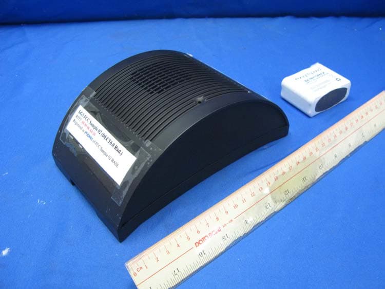
Click to zoom
Application Details
- Equipment Class
- PUB - Part 15 Unlicensed PCS Base Station
- Date of Grant
- Dec 07, 2011
- Application Purpose
- Original Equipment
- Date of Application
- Dec 07, 2011
- Equipment Note
- 1.9GHz DECT Student Group Speaker
- Frequency Range
- 1921.53600000 - 1928.44800000
- Company
- Lightspeed Technologies Inc.
- Country
- United States
Documents & Files
Document Text
Text extracted from the exhibit documents filed with the FCC. Open a document above to read the original.
Users Manual
User Manual Flexible Audio for Group Learning TABLE OF CONTENTS SECTION 1: 4Important Safety Instructions Overview5System Components and Unpacking 6Optional Components 7Charge Base Indicators 8Charge Base Connections 9Student Group Speaker Controls and Connections 12 Teacher Belt-pack Controls and Functions 13Remote Control Functions and Indicators 14Headset Functions SECTION 2:161. Determine Set-up Location Initial Set-up172. Connect the Base Station 183. Charge the FLEXCAT Components 194. Power On All Components 195. Ensure All Components Are Ready 206. Wearing the Headset 217. Determine Placement Location of Desktop Speakers SECTION 3:221. Operating the FLEXCAT Daily Operation23Using the Remote SECTION 4:241. Tips and Tricks to Successful Use Additional Information252. Multimedia Audio Integration 273. Connection to Assistive Listening Devices 284. Using Optional Speakers #5-6 SECTION 5:29Registration of Replacement or Additional Equipment Maintenance & Troubleshooting 30Group Speaker Registration Process 33Belt-Pack Registration 34Remote Registration 36Battery Replacement 39Troubleshooting SECTION 6:41Safety & Specifications Maintenance & Troubleshooting 42Safety Warnings and Certifications 43System Specifications 4 IMPORTANT SAFETY INSTRUCTIONS 1. Read these instructions. 2. Keep these instructions. 3. Heed all warnings. 4. Follow all instructions. 5. Do not use the apparatus near water. 6. Clean only with dry cloth. 7. Do not block any ventilation openings. Install in accordance with the manufacturer’s instructions. 8. Do not install near any heat sources such as radiators, heat registers, stoves, or other apparatus (including amplifiers) that produce heat. 9. Do not defeat the safety purpose of the polarized or grounding-type plug. A polarized plug has two blades with one wider than the other. A grounding- type plug has two blades and a third grounding prong. The wide blade or the third prong is provided for your safety. If the provided plug does not fit into your outlet, consult an electrician for replacement of the obsolete outlet. 10. Protect the power cord from being walked on or pinched particularly at plugs, convenience receptacles, and the point where they exit from the apparatus. 11. Only use attachments/ accessories specified by the manufacturer. 12. Use only with a cart, stand, tripod, bracket or table specified by the manufacturer, or sold with the apparatus. When a cart is used, use caution when moving the cart/ apparatus combination to avoid injury from tip-over. 13. Unplug this apparatus during lightning storms or when unused for long periods of time. 14. Refer all servicing to qualified service personnel. Servicing is required when the apparatus has been damaged in any way, such as power-supply cord or plug is damaged, liquid has been spilled or objects have fallen into the apparatus, the apparatus has been exposed to rain or moisture, does not operate normally, or has been dropped. 15. When the mains plug or appliance coupler used as the disconnect device, it shall remain readily operable. 16. Please keep the unit in a good ventilation environment. 5 1. Overview 2. Initial Set-up 3. DaiIy Operation 4. Additional Information 5. Maintenance & Troubleshooting 6. Safety & Specifications SECTION 1: OVERVIEW SYSTEM COMPONENTS AND UNPACKING The standard configuration of the FLEXCAT will contain: Teacher belt-pack (1) Teacher headset (1) Teacher remote control (1) Charging base station with power supply Student group speakers (x4) POWER REGISTER SPEAKERS LINK REMOTES REGISTER MULTIPACKS REGISTERLINK Vol Vol Mute 6 5 1 All 3 2 4 6 1. Overview 2. Initial Set-up 3. DaiIy Operation 4. Additional Information 5. Maintenance & Troubleshooting 6. Safety & Specifications OPTIONAL COMPONENTS Equipment which may be part of your FLEXCAT: Additional student group speakers Standard Components FCCBFLEXCAT charging base station with power supply FCGSFLEXCAT student group speaker with rechargeable battery pack FCTTFLEXCAT team-teacher kit (belt-pack, headset & remote control) FCBPFLEXCAT teacher belt-pack with rechargeable battery pack FCHRCFLEXCAT handheld remote control with rechargeable battery pack HS-FCOEFLEXCAT over-ear headset NH12V12V NiMH rechargeable battery pack for group speakers NH2.5V2.5V NiMH rechargeable battery pack for belt-pack and remote Optional Accessories CA-16VCCDC charging cable for optional group speakers #5-6 HS-MX500CFLEXCAT under-ear headset CA-MMC35353.5mm-3.5mm stereo audio cable Team teaching kit: 2nd belt-pack, headset and remote control Vol Vol Mute 6 5 1 All 3 2 4 7 1. Overview 2. Initial Set-up 3. DaiIy Operation 4. Additional Information 5. Maintenance & Troubleshooting 6. Safety & Specifications CHARGING BASE INDICATORS 1. Power Switch and LED: turns the FLEXCAT system power on or off. The LED will glow blue when the system is on. 2. Student Group Speaker Register and Link a. Register: press this button if there is a new speaker to be registered. b. Registration in progress: this LED will turn yellow to indicate the base station is searching for a speaker. c. Link established (1-6): these LEDs light up in green to indicate there is an audio link established with the corresponding group speaker. 3. Teacher belt-pack Register and Link a. Register: press this button if there is a new teacher belt-pack to be registered. b. Registration in progress: this LED will turn yellow to indicate the base station is searching for a teacher belt-pack. c. Link established (1-2): these LEDs light up in green to indicate there is an audio link established with the corresponding teacher belt- pack. 4. Teacher Remote Link Button and Indicator a. Register: press this button to search for a new teacher remote. b. Registration in progress: this LED will turn yellow to indicate the base station is searching for a teacher remote. 5. Student group speaker charging slots (1-4): insert each of the group speakers into these slots for daily recharging. 6. Belt-pack/Remote charging s…
Text truncated - open the document above for the full version.
Attestation Statements
UTAA{, Inc. |rffidavit of Participatio4 FCC Section 15 .307(b) Affidavit l, Michael Stima, Managing Director of UTAM, tnc., hereby swear and affirm that: Lightspeed Technologies Inc. is a participating member of UTAM, lnc. in good standing for purposes of Section 15.307(b) of the FCC rules. Subscribed to and sworn this 25th day of luly,2OtL UTAM, lnc. P.O. Box 8126 Bridgewater, New JerseY 08807 Tel: (508) 526-3636 ichael Stima, Managing Director Affidavit #: 1TSP072511
Cover Letter(s)
G Liql:tsp**# The trusted provider in classroom audio so/utions- September 1, 2011 To whom it may concern, Letter of Agency l, an officer of Liqhtspeed Technoloqies lnc. do hereby authorize lnteftek Testing Services (Mr. Ken Sit/Mr. Melvin Nip) to act on our behalf in front of the Federal Communications Commission with respect to all matters relating to cer.tification of equipment under Part 15 and/or Part 95 of the FCC Rules until further notice. I further certify that no party (as defined in S1.2002(b) of CFR 47, 2004) to this application, including myself, is subject to a denial of federal benefits, that includes FCC benefits, pursuant to Section 5301 of the Anti-Drug Abuse Act of 1988, 21 U S.C ., 862. Compliance Engineer Regards, John Chabot LIGHTSPEEDTECHNOLOGIESi ll5O9SWHERfulANROAD/TUALATIN,OR97062 /1WJ32.8999/\ffNA#.LIGHTSPEED-TEK.CCM
Cover Letter(s)
1) FCC ID: ORV-FCCB 2) FCC ID: ORV-FCGS 3) FCC ID: ORV-FCBP 4) FCC ID: ORV-FCHRC
External Photos
INTERTEK TESTING SERVICES External Photos FCC ID: ORV-FCGS IC: 1732B-FCGS external photos - 1 of 2 HK11100115 Job Number HK11100115 Job Number INTERTEK TESTING SERVICES External Photos FCC ID: ORV-FCGS IC: 1732B-FCGS external photos - 2 of 2 HK11100115 Job Number
ID Label/Location Info
1.4647 1.000 Keyed - Lower Right 1.500 0.9647 Model: FCGS DC: 12VDC, 2100 mAh LABEL P/N: 334-0038-00 FCC ID: ORV-FCGS IC : 1732B-FCGS .002 Label Specification Label P/N: Units: 334-0038-00 Inches Date:08/23/11 Dederick LIGHTSPEED TECHNOLOGIES, INC. www.lightspeed-tek.com 800.732.8999 LABEL SPECIFICATIONS 334-0038-00_FCBP_NAMEPLATE LABEL PART: REVISION: DATE: MATERIAL: ADHESIVE: WIDTH: HEIGHT: 334-0038-00 02 8/23/2011 POLYESTER, GLOSS UL APPROVED 1.500 INCHES 1.000 INCHES THICKNESS:2 MIL UL REQUIREMENTS: UL APPROVED PROCESS FOR MAT/ADH COLORS:PANTONE 327-2 BACKGROUND, WHITE TEXT SUBSTRATES: ENVIRONMENT: ABS INDOOR USE APPLICATION: SERIALIZED: SHEETS - APPLIED BY LIGHTSPEED NO REGULATORY REQUIREMENTS: TOLERANCES: UL, RoHS 0.002 INCH MATERIAL: OVERLAY: POLYESTER GLOSS SEMI-GLOSS MATTE TEXTURED LEXAN X Background Color to be: Pantone 327-2 PANTONE 327-2 SWATCH This device complies with Part 15 of the FCC Rules. Operation is subject to the following two conditions: (1) this device may not cause harmful interference, and (2) this device must accept any interference received, including interference that may cause undesired operation. “This Class B digital apparatus complies with Canadian ICES-003” DO NOT SCALE DRAWING PTC NOTES: UNLESS OTHERWISE SPECIFIED. +DFT 8.500 +DFT 5.000 .600 REV REF DESCRIPTION OF CHANGE CHK BY DATE 02 ADDED CUTOUT TN 01JUN11 LightSPEED Technologies, INC. 11509 SW HERMAN ROAD TUALATIN, OR 97062 USA SIGNATURE DATE RELEASED FOR PRODUCTION TOOLING DWN TN DIMENSIONS ARE IN INCHES TOLERANCES: UNLESS OTHERWISE SPECIFIED ENGR TN DEC ANLR CHKR .005 SCALE FIRST USED ON PROD NONE DAS MATERIAL PC/ABS - LIGHTSPEED BLACK FINISH SEE NOTES TITLE CASE, BASE, DAS POD CODE IDENT NO SIZE PART NUMBER REV C 395-0035-00 SH 1OF 1 02 16 FILM NUMBER: LS-104015. ALL OUTSIDE SURFACES: TEXTURE MOLD-TECH MT 1101014. UL REQUIRED MARKINGS & DOCUMENTATION FOR SUBPARTS WITH UL REQUIREMENTS, MUST BE INCLUDED WITH EACH SHIPMENT.13. PARTS MUST BE FABRICATED/MOLDED BY A UL RECOGNIZED FABRICATOR/MOLDER. MATERIAL AND PROCESS MUST BE UL RECOGNIZED.12 MOLD REVISION DATE CODE AND REVISION NUMBER TO BE ENGRAVED IN THIS AREA.11 PLASTIC RECYCLING CODE ">PC/ABS<" THIS AREA. RAISED/RECESSED TEXT HEIGHT .094 X .003/.00610. ALL MATERIALS AND PROCESSES SHALL BE ROHS COMPLIANT 9. MOLD DESIGN TO BE APPROVED BY LIGHTSPEED INC. 8. COSMETIC GRADE B ALL SURFACES 7. UL 94 HB FLAME RATED 6. CORNERS AND FILLETS MODELED SHARP: R .005 MAX 5. SINK: .005MAX 4. FLASH: .008 MAX 3. EJECTOR MARKS: +.xxx/-.yyy MAX 2. DEGATE: +.008/-.008 1. DIMENSIONING AND TOLERANCING PER ASME Y14.5M - 1994 02 16 16 11 12 TRX-FCGS-110603-0021 SN: 1.5 1.00 1.5 0.5 Model: FCGSDC: 12VDC, 2100 mAh LABEL P/N: 334-0038-00 FCC ID: ORV-FCGS IC : 1732B-FCGS This device complies with Part 15 of the FCC Rules. Operation is subject to the following two conditions: (1) this device may not cause harmful interference, and (2) this device must accept any interference received, including interference that may cause undesired operation. “This Class B digital apparatus complies with Canadian ICES-003”
Internal Photos
INTERTEK TESTING SERVICES Internal photos FCC ID: ORV-FCGS IC: 1732B-FCGS internal photos - 1 of 3 Speaker assembly Speaker Main PCB comp side (View 1) INTERTEK TESTING SERVICES Internal photos FCC ID: ORV-FCGS IC: 1732B-FCGS internal photos - 2 of 3 Speaker Main PCB comp side (View 2) Speaker Main PCB solder side INTERTEK TESTING SERVICES Internal photos FCC ID: ORV-FCGS IC: 1732B-FCGS internal photos - 3 of 3 Speaker Oscillator PCB comp side (View 1) Speaker Oscillator PCB comp side (View 2)
RF Exposure Info
INTERTEK TESTING SERVICES FCC ID: ORV-FCGS RF exposure info - 1 of 1 For Maximum Permissible Exposure (MPE) evaluation of the base unit, the maximum power density at 20 cm from this mobile transmitter shall be less than the General Population / Uncontrolled MPE limit in OET Bulletin 65. For the Speaker of tested model of FCGS, the maximum field strength measured (FS) was 100.8 dBμV/m. The distance (D) between the antenna and the equipment under test (EUT) was 3 meters. And the maximum source-based time-averaging duty factor in 1 device operation is 8.3%. From these data, the exposed power density at a distance (R) of 20cm from the center of radiation of the antenna can be calculated according to OET Bulletin 65 as follow: The radiated power (EIRP) = (FS*D) 2 / 30 = 3.61 mW The radiated (EIRP) source-based time-averaging output power = (3.61 * 0.083) mW = 0.30 mW The power density at 20 cm from the antenna = EIRP / 4πR 2 = 0.0001 mW cm -2 In the frequency range of 1,500 - 100,000MHz, the MPE limit is 1.0 mWcm -2 for general population and uncontrolled exposure. As the measured power density at 20cm from the transmitter is lower than the MPE limit, the compliance to the MPE limit can be ensured by indicating the minimum 20cm separation between the transmitter's radiating structures and body of the user or nearby persons. The following RF exposure statement is proposed to be included in the user manual: “ FCC RF Radiation Exposure Statement Caution: To maintain compliance with the FCC’s RF exposure guidelines, place the base unit at least 20cm from nearby persons.”
Test Report
INTERTEK TESTING SERVICES 26dB Emission Bandwidth Plots FCC ID: ORV-FCGS 26bw - 1 of 1 A0 Speaker, Lowest channel, Traffic carrier Speaker, Highest channel, Traffic carrier
Test Report
INTERTEK TESTING SERVICES Unwanted Emission Inside The Sub-Band Plots FCC ID: ORV-FCGS inband - 1 of 1 A0 Speaker, Lowest channel, Traffic carrier Speaker, Highest channel, Traffic carrier
Test Report
INTERTEK TESTING SERVICES Peak Transmit Power Plots FCC ID: ORV-FCGS IC: 1732B-FCGS peaktp - 1 of 2 A0 Speaker, Lowest channel, Traffic carrier Speaker, Middle channel, Traffic carrier INTERTEK TESTING SERVICES Peak Transmit Power Plots FCC ID: ORV-FCGS IC: 1732B-FCGS peaktp - 2 of 2 A0 Speaker, Highest channel, Traffic carrier
Test Report
INTERTEK TESTING SERVICES Power Spectral Density Plots FCC ID: ORV-FCGS psd - 1 of 1 A0 Speaker, Lowest channel, Traffic carrier Speaker, Highest channel, Traffic carrier
Test Report
- The test report only allows to be revised within the retention period unless further standard or the requirement was noticed. - This report is for the exclusive use of Intertek's Client and is provided pursuant to the agreement between Intertek and its Client. Intertek's responsibility and liability are limited to the terms and conditions of the agreement. Intertek assumes no liability to any party, other than to the Client in accordance with the agreement, for any loss, expense or damage occasioned by the use of this report. Only the Client is authorized to permit copying or distribution of this report and then only in its entirety. Any use of the Intertek name or one of its marks for the sale or advertisement of the tested material, product or service must first be approved in writing by Intertek. The observations and test results in this report are relevant only to the sample tested. This report by itself does not imply that the material, product, or service is or has ever been under an Intertek certification program. Intertek Testing Services Hong Kong Ltd. 2/F., Garment Centre, 576 Castle Peak Road, Kowloon, Hong Kong. Tel: (852) 2173 8888 Fax: (852) 2785 5487 Website: www.hk.intertek-etlsemko.com Lightspeed Technologies Inc. Application For 47 CFR Part 15: 2010 Certification RSS-213 Issue 2, December 2005 Equipment Certification Unlicensed Personal Communication Service Devices/ 2 GHz License-exempt Personal Communications Service Devices (Student Group Speaker) FCC ID: ORV-FCGS Model: FCGS IC: 1732B-FCGS Model: FCGS Test Report Number: HK11100115-1 Issue Date: November 01, 2011 MN/ cl INTERTEK TESTING SERVICES Test Report Number: HK11100115-1 Page 1 of 51 FCC ID: ORV-FCGS IC: 1732B-FCGS Table of Contents 1.0 Summary of Test Results........................................................................................ 4 2.0 General Description................................................................................................. 7 2.1 Product Description ................................................................................................. 7 2.2 Technical Description .............................................................................................. 7 2.3 Test Methodology.................................................................................................... 7 2.4 Test Facility............................................................................................................. 7 3.0 System Test Configuration...................................................................................... 9 3.1 Justification ............................................................................................................. 9 3.2 Conducted Emission Test Configuration ................................................................ 10 3.3 Conducted Monitoring and Operational Test Configuration.................................... 10 3.4 EUT Exercising Software....................................................................................... 10 3.5 Details of EUT and Description of Peripherals....................................................... 11 3.6 Measurement Uncertainty ..................................................................................... 11 4.0 Measurement Results............................................................................................ 13 4.1 Antenna Requirement........................................................................................... 13 4.2 Digital Modulation Techniques............................................................................... 13 4.3 Emission Bandwidth.............................................................................................. 14 4.4 Directional Gain of the Antenna ............................................................................. 14 4.5 Peak Transmit Power ............................................................................................ 15 4.6 Power Spectral Density ......................................................................................... 16 4.7 Automatic Discontinuation of Transmission............................................................ 16 4.8 Unwanted Emission Inside the Sub-Band .............................................................. 17 4.9 Emissions Outside the Sub-Band .......................................................................... 18 4.9.1 Radiated Emissions Configuration Photographs ................................................. 19 4.9.2 Radiated Emissions Data ................................................................................... 19 4.9.3 Field Strength Calculation................................................................................... 23 4.9.4 Average Factor Calculation and Transmitter ON Time Measurements ................ 24 4.10 Radiated Emissions from Receiver ...................................................................... 24 4.10.1 Radiated Emission Configuration Photographs ................................................. 25 4.10.2 Radiated Emissions Data ................................................................................. 25 4.11 AC Power Line Conducted Emissions ................................................................. 27 4.12 Radio Frequency Radiation Exposure.................................................................. 28 4.13 Radio Frequency Exposure Compliance.............................................................. 28 4.14 Frame Repetition Stability .................................................................................. 29 4.15 Frame Period and Jitter ...................................................................................... 30 4.16 Carrier Frequency Stability .................................................................................. 31 INTERTEK TESTING SERVICES Test Report Number: HK11100115-1 Page 2 of 51 FCC ID: ORV-FCGS IC: 1732B-FCGS Table of Con…
Text truncated - open the document above for the full version.
Test Setup Photos
INTERTEK TESTING SERVICES The Worst Case Configuration Photographs - Mode: Transmission FCC ID: ORV-FCGS IC: 1732B-FCGS config photos (radiated emission – speaker) - 1 of 1 Radiated Emission - Speaker Front View Rear View
Contact Information
Applicant
Mike Frost(Senior Engineer)
Technical Contact
Intertek Testing Services Hong Kong Ltd.Melvin Nip
[email protected]852-2173-8888
Flat D, 5/F., Garment Centre, · Kowloon · Hong Kong
Non-Technical Contact
Intertek Testing Services Hong Kong Ltd.Melvin Nip
[email protected]852-2173-8888
Test Firm
Intertek Testing Services Hong Kong Ltd.Billy Chow
Technical Specifications
| # | Rule Parts | Frequency Range | Power Output |
|---|---|---|---|
| 1 | 15D | 1.92 GHz - 1.93 GHz | 25.00 mW |
Other Applications from Lightspeed Technologies Inc.

ORV-LSRCT
May 21, 2026DECT base station
Equipment Class
PUB - Part 15 Unlicensed PCS Base Station
ORV-LSTCT
Apr 06, 2026DECT base station
Equipment Class
PUB - Part 15 Unlicensed PCS Base Station
ORV-LSRCN
Jun 01, 2021Redcat
Equipment Class
PUB - Part 15 Unlicensed PCS Base Station
ORV-LSMCN
May 23, 2021Media Connector
Equipment Class
PUB - Part 15 Unlicensed PCS Base Station
ORV-LSTCN
Apr 26, 2021Topcat
Equipment Class
PUB - Part 15 Unlicensed PCS Base Station