ORVACCAVWCAC-CAVWC
Lightspeed Technologies Inc.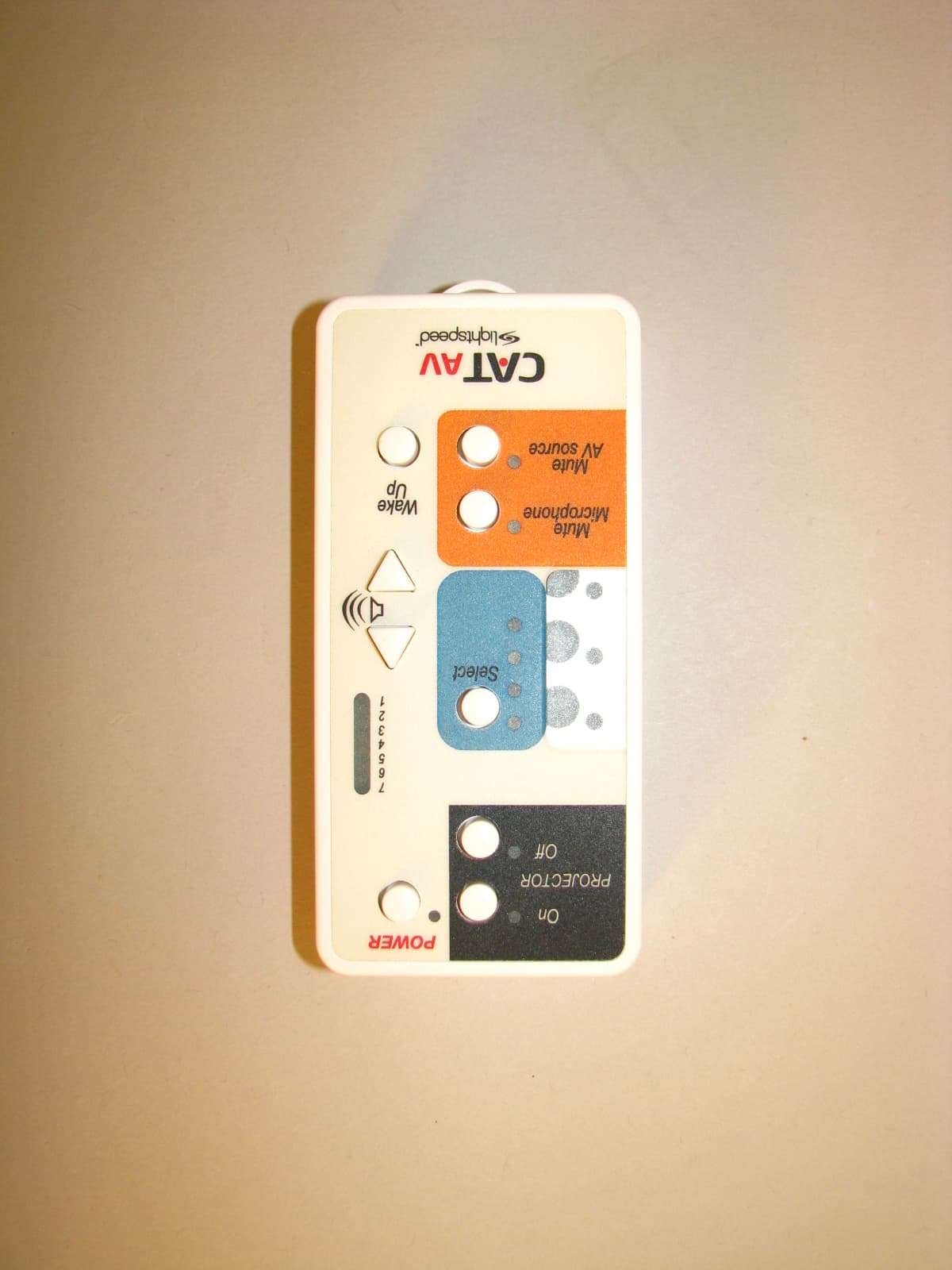
Click to zoom
Application Details
- Equipment Class
- DTS - Digital Transmission System
- Date of Grant
- Jul 28, 2010
- Application Purpose
- Original Equipment
- Date of Application
- Jul 28, 2010
- Equipment Note
- AC-CAVWC
- Frequency Range
- 2425.00000000 - 2475.00000000
- Company
- Lightspeed Technologies Inc.
- Country
- United States
Documents & Files
Document Text
Text extracted from the exhibit documents filed with the FCC. Open a document above to read the original.
Users Manual
TABLE OF CONTENTS SECTION 1: 4System Overview Overview 5System Components and Unpacking 9Applications Diagram 10Wireless Selector Controls 12I/O Switcher Front Panel Connectors & Controls 14Amplifier Controls & Connections 16Video Converter Connectors 17REDMIKE VC Controls & Connections 18RMC Cradle Charger Controls & Connections 19Infrared Sensor/Receiver (ISR) Connections SECTION 2: 20Important Safety Instructions Installation 21Pre-Installation 22System Installation Overview 22On/In Wall (No Enclosure) 25On Wall In Equipment Enclosure 26Switcher On Wall & Amplifier In Enclosure Above Ceiling SECTION 3: 271. Getting Started Set-up & Use 272. Pairing the Wireless Selector to the System 283. Setup Mode 294. Selecting Set-up Function 305. Microphone Volume Setting 316. Equalizer Level Setting 337. Tone Control Setting 348. Auto Power Down Time Setting 359. IR Learn Mode 3710. Set-up Copy Mode 3811. Un-Pair Wireless Selector Mode 3912. Reset to Factory Default Settings Mode 4013. Set-up Summary Chart 4114. Speaker Configuration 4515. IR Sensor/Receiver (ISR) Installation 4816. Charging the REDMIKE VC 4917. Set-up & Operation of REDMIKE VC SECTION 4: 50Troubleshooting Guide Troubleshooting 51Tips to Obtain Optimal Audio Performance SECTION 5: 52Warranty Statement Warranty & Specifications 53Warnings and Certifications 54FCC Statement 55System Specifications 4 1. Overview 2. Installation 3. Setup & Use 4. Troubleshooting 5. Warranty & Specifications 1. Overview 2. Installation 3. Setup & Use 4. Troubleshooting 5. Warranty & Specifications 5 CAT AV is truly the media hub of the classroom supporting speech reinforcement, full range multimedia sound, and video switching and control. The unique wireless control that can be mounted anywhere in the classroom and moved as often as necessary as there are no wires to install or move. You can locate it on your teaching wall or you can take with you for control anywhere in the room. Up to four infrared wireless REDMIKE Volume control microphones provide clear distribution of the teachers voice across the entire classroom. The AV switcher allows up to four audio and video inputs (two VGA and two composite). The switcher directs the selected AV input and sends the Audio via CAT-5 cable to the system amplifier. It also directs the selected video signal to the Video Converter module where it is converted back to its appropriate video connector and signal type to connect with the classroom projector. Designed for the classroom, CAT AV is fast and simple to install. Three CAT-5 twisted pair cables carry audio and video signals, control signals and power between all system modules and plenum rated speaker wire carries the amplified audio to the ceiling speaker(s). This user guide includes all of the information necessary for installation, set up and operation of the CAT AV system. Call Lightspeed Technologies, Inc. at 800- 732-8999 with any questions regarding this system. SECTION 1: OVERVIEW SYSTEM COMPONENTS AND UNPACKING The standard configuration of the CAT AV will contain: Amplifier and Cable Wireless Selector with Wall Mount I/O Switcher and Cable System Power Supply SYSTEM OVERVIEW 6 1. Overview 2. Installation 3. Setup & Use 4. Troubleshooting 5. Warranty & Specifications 1. Overview 2. Installation 3. Setup & Use 4. Troubleshooting 5. Warranty & Specifications 7 Optional WMQ (x 4) Optional DRQ (x 4) MCQ (x 1) SPEAKERS Charging Cradle and Power Supply REDMIKE VC Classroom Microphone iR Receiver and Cable Video Converter with Cables SYSTEM COMPONENTS AND UNPACKING CONT’D Standard Accessories AC-CAVWCWireless Control Panel AV-CAVSWI/O Switcher AV-VCONVideo converter AMP-CAVAmplifier PS-24V-2.5APower Supply RX-ISRIntegrated Sensor Receiver RMVREDMIKE Volume Control, Lavaliere cord, rechargeable AA batteries CA-CAT5e50CAT-5e cable (50 ft) BA-NH2A27Lightspeed AA rechargeable sensing battery BC-RMCCREDMIKE VC cradle charger PS-5V-1.0Cradle charger power supply AC-WCPWMWCP Wall Mount CA-35IREiR emitter to 3.5mm jack CA-VGA-1.518 inch VGA Cable CA-RCA-1.518 inch RCA Cable SPK-MCQCeiling Multimedia Speaker CA-PLSPK50Plenum speaker cable (50 ft) Velcro strip 2 inch AC-ENCSystem Enclosure AC-MNCAVUser Manual SPEAKERSContact Lightspeed at 800.732.8999 for speaker info SYSTEM COMPONENTS AND UNPACKING CONT’D 8 1. Overview 2. Installation 3. Setup & Use 4. Troubleshooting 5. Warranty & Specifications 1. Overview 2. Installation 3. Setup & Use 4. Troubleshooting 5. Warranty & Specifications 9 FEATURES WIRElESS CONTROl CAT AV’s wireless RF selector gives maximum flexibility for the teacher. It can be mounted to a wall or carried to give control anywhere in the classroom. AUdIO INPUTS CAT AV Switcher can select between four multimedia audio inputs (associated with the video inputs). MICROPhONE INPUTS Up to four infrared microphone transmitters can be used for the wireless transmission of the teacher’s voice. Each microphone has it’s own volume control or the wireless control panel can be used to set microphone output level. VIdEO INPUTS CAT AV Switcher can select between four inputs (two VGA and two composite). Ald AUdIO OUTPUT CAT AV outputs a mixed audio output (both multimedia audio and voice) through the ALD output jack located on the Switcher front panel. The output includes an independent volume control. This audio output can be used for connection to a recording or listening device. TWISTEd PAIR OUTPUTS CAT AV switcher outputs Audio to the Amplifier and Video to the Video Converter modules through two RJ-45 connectors. Audio and video signals can be transmitted via CAT-5 cable up to 100 ft away. ChECk AUdIO OUTPUT TO SPEAkERS 16 W per channel (32 W total) output for 1 to 4 speakers PAgEFIRST CAT AV connects to the classroom paging system using an optional paging sensor. When a page is sensed, it mutes all audio output from the CAT AV System during the page. Audio is returned to its normal levels when the page is complete. AUTO PROjECTOR ShUTdOWN To save energy a…
Text truncated - open the document above for the full version.
Cover Letter(s)
Northwest EMC TCB Compliance Opinion Rev. 12/08/09 LITS0005 Information about the Applicant Grantee (Company Name) Lightspeed Technologies, Inc. FCC Contact Person David Jordahl Address 11509 SW Herman Rd City, State, Zip Tualatin, OR 97062 Job Number LITS0005 Model AC-CAVWC FCC ID ORVACCAVWC Agent Approval Type Original Equipment Class DTS Digital Transmission System Rule Part 15.247 Overview This application is for the original approval of Lightspeed Technologies Model AC-CAVWC transceiver with FCC ID: ORVACCAVWC. This transceiver is used in an audio video system as remote controller and is intended to be used in a classroom environment. It is classified, for RF Exposure evaluation, as a portable transmitter. Because of the low power, SAR evaluation is not required. The transmitter operates under FCC rule part 47 Cfr 15.247 as a DTS device and is battery powered only with no connection to AC mains. Confidentiality requested for allowed files. Request is properly addressed and referenced. Recommendation All items have been resolved and completed to my satisfaction; therefore I recommend this application for approval. Signature 7/23/2010 Dave Tolman, TCB Committee
Operational Description
AC-CAVWC Remote Antenna This antenna complies with FCC requirements per 15.203 Gain: 2.8 dBi Description: This is a PCB trace antenna Location for mounting test antenna for EMI testing
RF Exposure Info
Compliance with 47 CFR 15.247(i) “Systems operating under the provisions of this section shall be operated in a manner that ensures that the public is not exposed to radio frequency energy levels in excess of the Commission's guidelines. See § 1.1307(b)(1) of this chapter.” The EUT is a DTS radio module. It can be considered a portable transmitter per 47 CFR 2.1093 because it can be used closer than 20cm to the user. The antenna is PCB trace with a peak gain of 2.8 dBi. . The maximum peak conducted output power is 0.58 mW. The maximum peak radiated power is 1.1 mW (EIRP) for FCC ID: ORVACCAVWC. The transmit frequency is 2425 to 2475 MHz, therefore the EUT does not require routine SAR evaluation because it falls below the low power threshold of 60/f(GHz)mW. Please see this excerpt from KDB 447498D01 Mobile Portable RF Exposure v04, item 2)(a)(i): "a device may be used in portable exposure conditions with no restrictions on host platforms when either the source-based time-averaged output power is <=60/f(GHz)mW or all measured 1-g SAR are <0.4 W.kg." The applicant’s DTS radio module, FCC ID: ORVACCAVWC, is compliant with the requirements of 15.247(i).
Test Report
Lightspeed Technologies, Inc. AC-CAVWC Report No. LITS0005.5 Report Prepared By www.nwemc.com 1-888-EMI-CERT © 2010 Northwest EMC, Inc 22975 NW Evergreen Parkway Suite 400 Hillsboro, Oregon 97124 Certificate of Test Last Date of Test: May 28, 2010 Lightspeed Technologies, Inc. Model: AC-CAVWC Emissions Test Description Specification Test Method Pass/Fail Occupied Bandwidth FCC 15.247 (DTS):2009 ANSI C63.10:2009 Pass Output Power FCC 15.247 (DTS):2009 ANSI C63.10:2009 Pass Band Edge Compliance FCC 15.247 (DTS):2009 ANSI C63.10:2009 Pass Spurious Conducted Emissions FCC 15.247 (DTS):2009 ANSI C63.10:2009 Pass Power Spectral Density FCC 15.247 (DTS):2009 ANSI C63.10:2009 Pass Spurious Radiated Emissions FCC 15.247 (DTS):2009 ANSI C63.10:2009 Pass Pulse Duration FCC 15.247 (DTS):2009 ANSI C63.10:2009 Pass Modifications made to the product See the Modifications section of this report Test Facility The measurement facility used to collect the data is located at: Northwest EMC, Inc. 22975 NW Evergreen Parkway, Suite 400 Hillsboro, OR 97124 Phone: (503) 844-4066 Fax: 844-3826 This site has been fully described in a report filed with and accepted by the FCC (Federal Communications Commission) and Industry Canada (Site filing #2834D-2). Approved By: Don Facteau, IS Manager NVLAP Lab Code: 200630-0 This report must not be used to claim product certification, approval, or endorsement by NVLAP, NIST, or any agency of the federal government of the United States of America. Product compliance is the responsibility of the client, therefore the tests and equipment modes of operation represented in this report were agreed upon by the client, prior to testing. This Report may only be duplicated in its entirety. The results of this test pertain only to the sample(s) tested. The specific description is noted in each of the individual sections of the test report supporting this certificate of test. Northwest EMC Revision History Revision 06/29/09 Barometric Pressure The recorded barometric pressure has been normalized to sea level. Revision Number Description Date Page Number 00 None Accreditations and Authorizations FCC Accredited by NVLAP for performance of FCC radio, digital, and ISM device testing. Our Open Area Test Sites, certification chambers, and conducted measurement facilities have been fully described in reports filed with the FCC and accepted by the FCC in letters maintained in our files. Northwest EMC has been accredited by ANSI to ISO / IEC Guide 65 as a product certifier. We have been designated by the FCC as a Telecommunications Certification Body (TCB). This allows Northwest EMC to certify transmitters to FCC specifications in accordance with 47 CFR 2.960 and 2.962. NVLAP Northwest EMC, Inc. is accredited under the United States Department of Commerce, National Institute of Standards and Technology, and National Voluntary Laboratory Accreditation Program for satisfactory compliance with the requirements of ISO/IEC 17025 for Testing Laboratories. The NVLAP accreditation encompasses Electromagnetic Compatibility Testing in accordance with the European Union EMC Directive 2004/108/EC, and ANSI C63.4. Additionally, Northwest EMC is accredited by NVLAP to perform radio testing in accordance with the European Union R&TTE Directive 1999/5/EEC, the requirements of FCC, and the RSS radio standards for Industry Canada. NVLAP LAB CODE 200629-0 NVLAP LAB CODE 200630-0 NVLAP LAB CODE 200676-0 NVLAP LAB CODE 200761-0 NVLAP LAB CODE 200881-0 Industry Canada Accredited by NVLAP for performance of Industry Canada RSS and ICES testing. Our Open Area Test Sites and certification chambers comply with RSS-Gen, Issue 2 and have been filed with Industry Canada and accepted. Northwest EMC has been accredited by ANSI to ISO / IEC Guide 65 as a product certifier. We have been designated by NIST and recognized by Industry Canada as a Certification Body (CB) per the APEC Mutual Recognition Arrangement (MRA). This allows Northwest EMC to certify transmitters to Industry Canada technical requirements. (Site Filing Numbers - Hillsboro: 2834D-1, 2834D-2, Sultan: 2834C-1, Irvine: 2834B-1, 2834B-2, Brooklyn Park: 2834E-1) CAB Designated by NIST and validated by the European Commission as a Conformity Assessment Body (CAB) to conduct tests and approve products to the EMC directive and transmitters to the R&TTE directive, as described in the U.S. - EU Mutual Recognition Agreement. NEMKO Assessed and accredited by NEMKO (Norwegian testing and certification body) for European emissions and immunity testing. As a result of NEMKO's laboratory assessment, they will accept test results from Northwest EMC, Inc. for product certification (Authorization No. ELA 119). Accreditations and Authorizations Australia/New Zealand The National Association of Testing Authorities (NATA), Australia has been appointed by the ACA as an accreditation body to accredit test laboratories and competent bodies for EMC standards. Accredited test reports or assessments by competent bodies must carry the NATA logo. Test reports made by an overseas laboratory that has been accredited for the relevant standards by an overseas accreditation body that has a Mutual Recognition Agreement (MRA) with NATA are also accepted as technical grounds for product conformity. The report should be endorsed with the respective logo of the accreditation body (NVLAP). VCCI Accepted as an Associate Member to the VCCI, Acceptance No. 564. Conducted and radiated measurement facilities have been registered in accordance with Regulations for Voluntary Control Measures, Article 8. (Registration Numbers. - Hillsboro: C-1071, R-1025, G-84, C-2687, T-1658, and R-2318, Irvine: R-1943, G-85, C- 2766, and T-1659, Sultan: R-871, G-83, C-1784, and T-1511, Brooklyn Park: R-3125, G-86, G-141, C-3464, and T-1634). BSMI Northwest EMC has been designated by NIST and validated by C-Taipei (BSMI) as a CAB to conduct tests as described in the APEC Mutual Recognition Agreement (US0017). License No.SL2…
Text truncated - open the document above for the full version.
Test Setup Photos
NORTHWEST EMC OCCUPIED BANDWIDTH XMit 2010.01.14 NORTHWEST EMC OUTPUT POWER XMit 2010.01.14 NORTHWEST EMC BAND EDGE COMPLIANCE XMit 2010.01.14 NORTHWEST EMC SPURIOUS CONDUCTED EMISSIONS XMit 2010.01.14 NORTHWEST EMC POWER SPECTRAL DENSITY XMit 2010.01.14 NORTHWEST EMC SPURIOUS RADIATED EMISSIONS PSA 2008.07.21 NORTHWEST EMC SPURIOUS RADIATED EMISSIONS PSA 2008.07.21 NORTHWEST EMC SPURIOUS RADIATED EMISSIONS PSA 2008.07.21 NORTHWEST EMC PULSE DURATION XMit 2010.01.14
Contact Information
Applicant
Mike Frost(Senior Engineer)
Test Firm
Northwest EMC, Inc.Greg Kiemel
Technical Specifications
| # | Rule Parts | Frequency Range | Power Output |
|---|---|---|---|
| 1 | 15C | 2.42 GHz - 2.48 GHz | 580.00 µW |
Other Applications from Lightspeed Technologies Inc.

ORV-LSRCT
May 21, 2026DECT base station
Equipment Class
PUB - Part 15 Unlicensed PCS Base Station
ORV-LSTCT
Apr 06, 2026DECT base station
Equipment Class
PUB - Part 15 Unlicensed PCS Base Station
ORV-LSRCN
Jun 01, 2021Redcat
Equipment Class
PUB - Part 15 Unlicensed PCS Base Station
ORV-LSMCN
May 23, 2021Media Connector
Equipment Class
PUB - Part 15 Unlicensed PCS Base Station
ORV-LSTCN
Apr 26, 2021Topcat
Equipment Class
PUB - Part 15 Unlicensed PCS Base Station