OVFKWC-2325
Kyocera International, Inc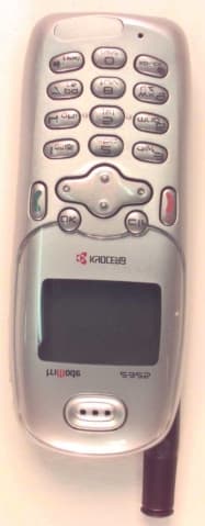
Click to zoom
Application Details
- Equipment Class
- PCE - PCS Licensed Transmitter held to ear
- Date of Grant
- Jun 23, 2002
- Application Purpose
- Original Equipment
- Date of Application
- May 19, 2002
- Frequency Range
- 1851.25000000 - 1908.75000000
- Company
- Kyocera International, Inc
- Country
- United States
Documents & Files
Document Text
Text extracted from the exhibit documents filed with the FCC. Open a document above to read the original.
Users Manual
X4 rëÉêÛë=dìáÇÉ=Ñçê=íÜÉ=hóçÅÉê~=OPOR=éÜçåÉ qÜáë=ã~åì~ä=áë=Ä~ëÉÇ=çå=íÜÉ=éêçÇìÅíáçå=îÉêëáçå=çÑ=íÜÉ=hóçÅÉê~=OPOR=éÜçåÉK=pçÑíï~êÉ=ÅÜ~åÖÉë=ã~ó=Ü~îÉ=çÅÅìêêÉÇ=~ÑíÉê=íÜáë=éêáåíáåÖK=hóçÅÉê~=êÉëÉêîÉë=íÜÉ=êáÖÜí=íç=ã~âÉ=ÅÜ~åÖÉë=áå=íÉÅÜåáÅ~ä=~åÇ=éêçÇìÅí=ëéÉÅáÑáÅ~íáçåë=ïáíÜçìí=éêáçê=åçíáÅÉK=qÜÉ=éêçÇìÅíë=~åÇ=ÉèìáéãÉåí=ÇÉëÅêáÄÉÇ=áå=íÜáë=ÇçÅìãÉåí~íáçå=~êÉ=ã~åìÑ~ÅíìêÉÇ=ìåÇÉê=äáÅÉåëÉ=Ñêçã=nr^i`ljj=fåÅçêéçê~íÉÇ=ìåÇÉê=çåÉ=çê=ãçêÉ=çÑ=íÜÉ=ÑçääçïáåÖ=rKpK=é~íÉåíëWQIVMNIPMT RIMRSINMV RIMVVIOMQ RINMNIRMN RINMPIQRVRINMTIOOR RINMVIPVM RINVPIMVQ RIOOUIMRQ RIORTIOUPRIOSRINNV RIOSTIOSN RIOSTIOSO RIOUMIQTO RIOUPIRPSRIOUVIROT RIPMTIQMR RIPMVIQTQ RIPPTIPPU RIPPVIMQSRIPQNIQRS RIPUPIONV RIPVOIOUT RIPVSIRNS aPRSIRSMRIQMUISVT RIQNQITOU RIQNQITVS RIQNSITVT RIQOSIPVORIQPTIMRR aPSNIMSR RIQQOIPOO RIQQOISOT RIQROIQTPRIQSNISPV RIQSVINNR RIQSVIQTN RIQTNIQVT RIQTRIUTMRIQTVIQTR RIQUPISVS RIQURIQUS RIQUTINTR RIQVMINSRRIQVTIPVR RIQVVIOUM RIRMQITTP RIRMSIUSR RIRMVIMNRRIRMVIMPR RIRNNIMST RIRNNIMTP RIRNPINTS RIRNRINTTRIRNTIPOP RIRNVITSN RIROUIRVP RIRPMIVOU RIRPPIMNNRIRPRIOPV RIRPVIRPN RIRQQINVS RIRQQIOOP RIRQSIQRVRIRQUIUNO RIRRVIUUN RIRRVIUSR RIRSNISNU RIRSQIMUPRIRSSIMMM RIRSSIOMS RIRSSIPRT RIRSUIQUP RIRTQITTPRIRTQIVUT aPTRITQM RIRTSISSO RIRTTIMOO RIRTTIOSRaPTRIVPT RIRUUIMQP aPTSIUMQ RIRUVITRS RIRVMIMSVRIRVMIQMS RIRVMIQMU RIRVOIRQU RIRVQITNU RIRVSIRTMRISMMITRQ RISMOIUPQ RISMOIUPP RISMPIMVS RISMQIQRVRISMQITPM RISMUITOO RISNQIUMS RISNTIMSM RISONITRORISONITUQ RISONIURP RISORIUTS RISOTIURT RISOVIVRRRISOVIVTR RISPUIQNO RISQMIQNQ RISQOIPVU RISQQIRVNRISQQIRVS RISQSIVVN RISROIUNQ RISRQIVTV RISRRIOOMRISRTIQOM RISRVIRSV RISSPIUMT RISSSINOO RISTPIORVRISTRIRUN RISTRISQQ RISUMIPVR RISUTIOOV aPUSINUSRISUVIRRT RISVNIVTQ RISVOIMMS RISVSIQSU RISVTIMRRRITMPIVMO RITMQIMMN RITMUIQQU RITNMIRON RITNMITRURITNMITSU RITNMITUQ RITNRIOPS RITNRIROS RITOOIMQQRITOOIMRP RITOOIMSN RITOOIMSP RITOQIPUR RITOTINOPRITOVIRQM RITPOINPQ RITPOIPQN RITPQITNS RITPTISUTRITPTITMU RITQOITPQ aPVPIURS RITQUINMQ RITRNITORRITRNITSN RITRNIVMN RITRQIRPP RITRQIRQO RITRQITPP RITRTITST RITRTIURU RITRUIOSS RITSNIOMQ RITSQISUTRITTQIQVS RITTTIVVM RITTUIMOQ RITTUIPPU RITUNIRQPRITUNIURS RITUNIUST RITUQIQMS RITUQIRPO RITVMIRUVRITVMISPO RITVPIPPU aPVTINNM RITVVIMMR RITVVIORQRIUMOINMR RIUMRISQU RIUMRIUQP RIUNOIMPS RIUNOIMVQRIUNOIMVT RIUNOIRPU RIUNOISMT RIUNOISRN RIUNOIVPURIUNUIUTN RIUOOIPNU RIUORIORP RIUOUIPQU RIUOUISSNRIUPRIMSR RIUPRIUQT RIUPVIMRO RIUQNIUMS RIUQOINOQRIUQQITUQ RIUQQIUUR RIUQQIUVV RIUQQIVUR RIUQUIMSPRIUQUIMVV RIURMISNO RIUROIQON RIURQIRSR RIURQITUSRIURTINQT RIURVISNO RIURVIUPU RIURVIUQM RIUSNIUQQRIUSOIQTN RIUSOIQTQ RIUSQITSM RIUSQITSP RIUSTIROTRIUSTITSP RIUTMIQOT RIUTMIQPN RIUTMISTQ RIUTOIQUNRIUTOITTQ RIUTOITTR RIUTOIUOP RIUTTIVQO RIUTUIMPSRIUTMISPN RIUUNIMRP RIUUNIPSU RIUUQINRT RIUUQINVPRIUUQINVS RIUVOINTU RIUVOITRU RIUVOITTQ RIUVOIUNSRIUVOIVNS RIUVPIMPR aQMTITMN RIUVUIVOM RIVMPIRRQRIVMPIUSO aQMVIRSN RIVMTINST RIVMVIQPQ RIVNMITRORIVNNINOU RIVNOIUUO aQNMIUVP RIVNQIVRM RIVNRIOPRRIVNTITMU RIVNTIUNN RIVNTIUNO RIVNTIUPT RIVOMIOUQaQNNIUOP RIVOPISRM RIVOPITMR RIVOSINQP RIVOSIQTMRIVOSIRMM RIVOSITUS RIVPMIOPM RIVPMISVO=líÜÉê=é~íÉåíë=éÉåÇáåÖKhóçÅÉê~=áë=~=êÉÖáëíÉêÉÇ=íê~ÇÉã~êâ=çÑ=hóçÅÉê~=`çêéçê~íáçåK=nr^i`ljj=áë=~=êÉÖáëíÉêÉÇ=íê~ÇÉã~êâ=çÑ=nr^i`ljj=fåÅçêéçê~íÉÇK=_êáÅâ=^íí~Åâ=áë=~=íê~ÇÉã~êâ=çÑ=hóçÅÉê~=táêÉäÉëë=`çêéK=`~îÉêå=`ê~ïä=áë=~=íê~ÇÉã~êâ=çÑ=aê~ÖçåiçêÇ=båíÉêéêáëÉëI=fåÅK=qÉíêáë=áë=~=êÉÖáëíÉêÉÇ=íê~ÇÉã~êâ=çÑ=_äìÉ=mä~åÉí=pçÑíï~êÉI=fåÅK=léÉåï~îÉ=áë=~=êÉÖáëíÉêÉÇ=íê~ÇÉã~êâ=çÑ=léÉåï~îÉ=póëíÉãë=fåÅçêéçê~íÉÇK=ÉwáqÉñí=áë=~=êÉÖáëíÉêÉÇ=íê~ÇÉã~êâ=çÑ=wá=`çêéçê~íáçåK=^ää=çíÜÉê=íê~ÇÉã~êâë=~êÉ=íÜÉ=éêçéÉêíó=çÑ=íÜÉáê=êÉëéÉÅíáîÉ=çïåÉêëK`çéóêáÖÜí=«=OMMO=hóçÅÉê~=táêÉäÉëë=`çêéK=^ää=êáÖÜíë=êÉëÉêîÉÇK=mêáåíÉÇ=áå=íÜÉ=råáíÉÇ=pí~íÉë=çÑ=^ãÉêáÅ~K=UOJ_TVPTJNbkI=oÉîK=uQ c``Lf`=kçíáÅÉqÜáë=ÇÉîáÅÉ=ÅçãéäáÉë=ïáíÜ=é~êí=NR=çÑ=íÜÉ=c``=êìäÉëK=léÉê~íáçå=áë=ëìÄàÉÅí=íç=íÜÉ=ÑçääçïáåÖ=íïç=ÅçåÇáíáçåëW=ENF=qÜáë=ÇÉîáÅÉ=ã~ó=åçí=Å~ìëÉ=Ü~êãÑìä=áåíÉêÑÉêÉåÅÉI=~åÇ=EOF=íÜáë=ÇÉîáÅÉ=ãìëí=~ÅÅÉéí=~åó=áåíÉêÑÉêÉåÅÉ=êÉÅÉáîÉÇI=áåÅäìÇáåÖ=áåíÉêÑÉêÉåÅÉ=íÜ~í=ã~ó=Å~ìëÉ=ìåÇÉëáêÉÇ=çéÉê~íáçåK=qç=Åçãéäó=ïáíÜ=c``=ê~Çá~íáçå=ÉñéçëìêÉ=êÉèìáêÉãÉåíëI=ìëÉ=çÑ=íÜáë=ÇÉîáÅÉ=Ñçê=ÄçÇóJïçêå=çéÉê~íáçå~ä=ÅçåÑáÖìê~íáçåë=áë=äáãáíÉÇ=íç=~ÅÅÉëëçêáÉë=íÉëíÉÇ=~åÇ=~ééêçîÉÇ=Äó=hóçÅÉê~=táêÉäÉëë=`çêéK=Eht`FK=líÜÉê=~ÅÅÉëëçêáÉë=ìëÉÇ=ïáíÜ=íÜáë=ÇÉîáÅÉ=Ñçê=ÄçÇóJïçêå=çéÉê~íáçåë=ãìëí=åçí=Åçåí~áå=~åó=ãÉí~ääáÅ=ÅçãéçåÉåíë=~åÇ=ãìëí=éêçîáÇÉ=~í=äÉ~ëí=OOKR=ãã=ëÉé~ê~íáçå=Çáëí~åÅÉ=áåÅäìÇáåÖ=íÜÉ=~åíÉåå~=~åÇ=íÜÉ=ìëÉêÛë=ÄçÇóKqÜáë=ãçÇÉä=éÜçåÉ=ãÉÉíë=íÜÉ=ÖçîÉêåãÉåíÛë=êÉèìáêÉãÉåíë=Ñçê=ÉñéçëìêÉ=íç=ê~Çáç=ï~îÉëKvçìê=ïáêÉäÉëë=éÜçåÉ=áë=~=ê~Çáç=íê~åëãáííÉê=~åÇ=êÉÅÉáîÉêK=fí=áë=ÇÉëáÖåÉÇ=~åÇ=ã~åìÑ~ÅíìêÉÇ=åçí=íç=ÉñÅÉÉÇ=íÜÉ=Éãáëëáçå=äáãáíë=Ñçê=ÉñéçëìêÉ=íç=ê~Çáç=ÑêÉèìÉåÅó=EocF=ÉåÉêÖó=ëÉí=Äó=íÜÉ=cÉÇÉê~ä=`çããìåáÅ~íáçåë=`çããáëëáçå=çÑ=íÜÉ=rKpK=dçîÉêåãÉåíK=qÜÉëÉ=äáãáíë=~êÉ=é~êí=çÑ=ÅçãéêÉÜÉåëáîÉ=ÖìáÇÉäáåÉë=~åÇ=Éëí~ÄäáëÜ=éÉêãáííÉÇ=äÉîÉäë=çÑ=oc=ÉåÉêÖó=Ñçê=íÜÉ=ÖÉåÉê~ä=éçéìä~íáçåK=qÜÉ=ÖìáÇÉäáåÉë=~êÉ=Ä~ëÉÇ=çå=ëí~åÇ~êÇë=íÜ~í=ïÉêÉ=ÇÉîÉäçéÉÇ=Äó=áåÇÉéÉåÇÉåí=ëÅáÉåíáÑáÅ=çêÖ~åáò~íáçåë=íÜêçìÖÜ=éÉêáçÇáÅ=~åÇ=íÜçêçìÖÜ=Éî~äì~íáçå=çÑ=ëÅáÉåíáÑáÅ=ëíìÇáÉëK=qÜÉ=ëí~åÇ~êÇë=áåÅäìÇÉ=~=ëìÄëí~åíá~ä=ë~ÑÉíó=ã~êÖáå=ÇÉëáÖåÉÇ=íç=~ëëìêÉ=íÜÉ=ë~ÑÉíó=çÑ=~ää=éÉêëçåëI=êÉÖ~êÇäÉëë=çÑ=~ÖÉ=~åÇ=ÜÉ~äíÜKqÜÉ=ÉñéçëìêÉ=ëí~åÇ~êÇ=Ñçê=ïáêÉäÉëë=ãçÄáäÉ=éÜçåÉë=Éãéäçóë=~=ìåáí=çÑ=ãÉ~ëìêÉãÉåí=âåçïå=~ë=íÜÉ=péÉÅáÑáÅ=^Äëçêéíáçå=o~íÉI=çê=p^oK=qÜÉ=p^o=äáãáí=ëÉí=Äó=íÜÉ=c``=áë=NKS=tLâÖKG=qÉëíë=Ñçê=p^o=~êÉ=ÅçåÇìÅíÉÇ=ìëáåÖ=ëí~åÇ~êÇ=çéÉê~íáåÖ=éçëáíáçåë=ëéÉÅáÑáÉÇ=Äó=íÜÉ= c``=ïáíÜ=íÜÉ=éÜçåÉ=íê~åëãáííáåÖ=~í=áíë=ÜáÖÜÉëí=ÅÉêíáÑáÉÇ=éçïÉê=äÉîÉä=áå=~ää=íÉëíÉÇ=ÑêÉèìÉåÅó=Ä~åÇëK=^äíÜçìÖÜ=íÜÉ=p^o=áë=ÇÉíÉêãáåÉÇ=~í=íÜÉ=ÜáÖÜÉëí=ÅÉêíáÑáÉÇ=éçïÉê=äÉîÉäI=íÜÉ=~Åíì~ä=p^o=äÉîÉä=çÑ=íÜÉ=éÜçåÉ=ïÜáäÉ=çéÉê~íáåÖ=Å~å=ÄÉ=ïÉää=ÄÉäçï=íÜÉ=ã~ñáãìã=î~äìÉK=qÜáë=áë=ÄÉÅ~ìëÉ=íÜÉ=éÜçåÉ=áë=ÇÉëáÖåÉÇ=íç=çéÉê~íÉ=~í=ãìäíáéäÉ=éçïÉê=äÉîÉäë=ëç=~ë=íç=ìëÉ=çåäó=íÜÉ=éçïÉê=êÉèìáêÉÇ=íç=êÉ~ÅÜ=íÜÉ=åÉíïçêâK=få=ÖÉåÉê~äI=íÜÉ=ÅäçëÉê=óçì=~êÉ=íç=~=ïáêÉäÉëë=Ä~ëÉ=ëí~íáçå=~åíÉåå~I=íÜÉ=äçïÉê=íÜÉ=éçïÉê=çìíéìíK=_ÉÑçêÉ=~=éÜçåÉ=ãçÇÉä=áë=~î~áä~ÄäÉ=Ñçê=ë~äÉ=íç=íÜÉ=éìÄäáÅI=áí=ãìëí=ÄÉ=íÉëíÉÇ=~åÇ=ÅÉêíáÑáÉÇ=íç=íÜÉ=c``=íÜ~í=áí=ÇçÉë=åçí=ÉñÅÉÉÇ=íÜÉ=äáãáí=Éëí~ÄäáëÜÉÇ=Äó=íÜÉ=ÖçîÉêå…
Text truncated - open the document above for the full version.
Attestation Statements
Applicant: KWC Corp. FCC ID: OVFKWC-2325 Request of Confidentiality Federal Communications Commission Authorization and Evaluation Division Re:Request of Confidentiality Pursuant to Sections 0.457 and 0.459 of the Commission’s Rules, the Applicant hereby requests confidential treatment of information accompanying this Application as outlined below: All schematics/block diagrams All parts lists The above materials contain trade secrets and proprietary information not customarily released to the public. The public disclosure of these matters might be harmful to the Applicant and provide unjustified benefits to its competitors. The Applicant understands that pursuant to Rule 0.457, disclosure of this Application and all accompanying documentation will not be made before the date of the Grant for this Application. Kyocera Wireless Corporation Lin Lu EMC Engineer, senior staff
Cover Letter(s)
Applicant: KWC Corp. FCC ID: OVFKWC-2325 1 Cover Letter Federal Communications Commission Authorization and Evaluation Division Re:Application for Cellular and PCS Transceiver Type Acceptance Kyocera Wireless Corporation (KWC) herein submits the Application for Equipment Authorization (FCC Form 731) and Exh ibits for Type Acceptance of a Cellular & PCS Transceiver, FCC ID: OVFKWC-2325. Applicant:Kyocera Wireless Corporation 10300 Campus Point Drive San Diego, CA 92121-1522 Manufacture:Kyocera Wireless Corporation 10300 Campus Point Drive San Diego, California 92121 The equipment, KWC model # KWC-2325, is for mobile station cell ular and PCS system use. The KWC-2325 is in full compliance with all parts of EIA/TIA/IS-98-B&D Mobile Station-Land Station Compatibility Specification, issue July 2000 and March 2001, and also in full compliance with all parts of ANSI J-STD-018, Recommended Minimum Performance Requirements for 1.8 to 2 GHz Code Division Multiple Access (CDMA) Personal Stations, iss ue July 1996. The KWC-2325 has E911 Phase II GPS capability. Information concerning how the ESN protection requirements are met is provided in Exhibit 3. Kyocera Wireless Corporation Lin Lu EMC Engineer, senior staff
Cover Letter(s)
This document was generated in response to a request for additional technical information by Joe Dichoso in regards to the type approval of the KWC-2325. The information included in related to the 5 specific topics discussed in the following email received by Lin Lu on June 17, 2002: From: [email protected] Date: Mon, 17 Jun 2002 13:59:28 -0400 (EDT) To: [email protected] X-BigFish: cs0v To: Lin Lu, Kyocera Wireless Corp From: Joe Dichoso [email protected] FCC Application Processing Branch Re: FCC ID OVFKWC-2325 Applicant: Kyocera Wireless Corp Correspondence Reference Number: 23139 731 Confirmation Number: EA645242 Please address the following RF safety and EMC issues. RF safety... 1) Op Desc exhibit missing. 2) Probe cal. cert. shows head factors only. Please describe how body factors were obtained, or submit body cal. cert. 3) pg 3 of users manual: FCC ID is wrong - hyphen missing EMC QUESTIONS. 1) The output powers listed on page 6 of the test report does not agree with those on Pages 25 and Pages 26. Pages 25 and 25 was used for the requested radiated output powers. Please explain. The output power in the test report must also agree with the SAR report. 2) What is the second test report for? Please explain. RF Safety – 1) Operational Description under FCC Rules Part 2 Section 2.1033 (c) The operational description specified in FCC rules section 2.1033 (c) was included in the first test report, named “KWC-2345_part22&24 test report”, Exhibit 2, pp. 5 ~ 23. The circuit description specified in Section 2.1033 (c) (10) was contained in Exhibit 2, page 6 ~ 23. The schematic diagram was uploaded to FCC OET web site on May 21, 2002. In case, some of files were missing during the uploading. The Exhibit 2 (operational description) has been re-sent to FCC via OET electronic filing web sit, as a separate Exhibit. Please let us know if any further information is needed. 2) Probe Factor for Muscle Tissues Based on DASY3-user manual Page 49 and the email from Schmid & Partner Engineering AG, the probe conversion factor in muscle tissue was set to 3% lower than for brain tissue in 835MHz frequency, and 10% lower than for brain tissue in 1800MHz. The related pages of DASY3-user manual, SPEAG email are attached in the proceeding pages. User ManualPage 48 of 66 Schmid & Partner Engineering AG, August 99 4.5.3 Connection between device, liquid, and probe parameters The electric parameters of the simulation liquid are frequency dependent. Unluckily, this frequency dependency in the homogeneous simulation liquid is different than in the complex cellstructure of the simulated tissue. Since each solution can simulate the tissue only within a limited frequency range, several mixtures are necessary to cover the total MTE frequency range. Within a frequency bandwidth of at least 20%, the same solution can be used with small errors in the SAR. However, the measured parameters at the actual frequency should be used in the software (see RG: 2.3 Medium ). The DASY3 software checks the selected solution against the device frequency to prevent incorrect combinations which could lead to undetected measurement errors. To that purpose, each dataset for the media includes frequency range settings. If the frequency of the selected device is not within the range of the selected media, the system will issue an error message. It is highly recommended to use different media datasets for different frequencies, even for the same liquid. If one liquid is used for 835MHz and 900MHz two datasets with the corresponding parameters should be used (e.g., with frequency ranges 800 - 850 MHz and 870 - 920 MHz). The liquid parameters should be remeasured and adjusted in the software regularly (see RG: 2.3 Medium ). The probe conversion factor (and boundary effect) depends on the frequency and the liquid parameters. For each dosimetric probe, many different sets of conversion factors and boundary correction data can be defined (RG: 2.6.1 E-Field Probe). Each set includes range settings for permittivity, conductivity and frequency. The probe conversion factors can be selected manually or automatically (RG: 2.6.1 E-Field Probe). In the (recommended) automatic selection mode, the software searches for the first conversion factor in the list, whose permittivity and conductivity and frequency range covers the selected device frequency and liquid parameters. If no valid conversion factor can be found, the system will issue an error message when trying to measure SAR. The same error message appears if the manually selected conversion factors do not correspond with the device or the media. The conversion factors are determined during probe calibration. SPEAG probes are by default calibrated at 900MHz and 1800MHz in brain simulating tissue. The range settings in the probe configuration file are selected to guarantee the specified probe uncertainties. If you want to perform SAR measurements in other liquids (e.g., 835MHz muscle tissue), the DASY3 system will complain. There are several ways to overcome the problem: lIncrease the range settings in the probe document, leaving the conversion factors as they are. This will permit the measurement, although with increased uncertainty. For small changes in the parameters or frequency the error is small (see box below). lAdd a new conversion factor set for the new liquid or frequency. The conversion factor can be estimated from the existing conversion factors (see box below). lOrder special calibrations for the probe. The following sensitivities of the conversion factor can be used to estimate the conversion factor for other frequencies or media. They are assessed from special calibrations with the ET3DVx probe series. (They cannot be applied for other probe types!) Note:The system automatically selects the first valid conversion factor. If you define conversion factors with a reduced frequency and parameter range, make sure that this range is not already covered by an other set further up in the list.…
Text truncated - open the document above for the full version.
External Photos
Applicant: KWC Corp.FCC ID: OVFKWC-2325 Exhibit 19 External Photographs Front Applicant: KWC Corp.FCC ID: OVFKWC-2325 Back Applicant: KWC Corp.FCC ID: OVFKWC-2325 Side
ID Label/Location Info
Applicant: KWC Corp.FCC ID: OVFKWC-2325 Exhibit 18 FCC Identification Label Information FCC ID: KWCQCP-2345 Photo of the ID: Applicant: KWC Corp.FCC ID: OVFKWC-2325 The label will be placed in the battery compartment.
ID Label/Location Info
This document was generated in response to a request for FCC label information by Jaunice Green in regards to the type approval of the KWC-2325. The information included in related to the specific topic discussed in the following email received by Lin Lu on May 22, 2002: From: [email protected] Date: Wed, 22 May 2002 14:46:08 -0400 (EDT) To: [email protected] Subject: FCC IDENTIFICATION LABEL To: Lin Lu, Kyocera Wireless Corp From: Jaunice Green [email protected] FCC Application Processing Branch Re: FCC ID OVFKWC-2325 Applicant: Kyocera Wireless Corp Correspondence Reference Number: 22968 731 Confirmation Number: EA645242 The FCC Identifier listed on the label is not in the correct label format. Please submit a revised label with the FCC ID:... and not FCC.... that would indicate the correct label format. 1) FCC ID and Location Per the request by Jaunice Green, the FCC Identifier for KWC-2325 has been changed to the correct format. The Exhibit 18_FCC ID & location is attached to this response in the following pages. Applicant: KWC Corp.FCC ID: OVFKWC-2325 Exhibit 18 FCC Identification Label Information FCC ID: OVFKWC-2325 Photo of the ID: Applicant: KWC Corp.FCC ID: OVFKWC-2325 The label will be placed in the battery compartment.
Internal Photos
Applicant: KWC Corp.FCC ID: OVFKWC-2325 Exhibit 19 Internal Photographs Front Housing Assembling Applicant: KWC Corp.FCC ID: OVFKWC-2325 Applicant: KWC Corp.FCC ID: OVFKWC-2325 Applicant: KWC Corp.FCC ID: OVFKWC-2325 Key Board Front Applicant: KWC Corp.FCC ID: OVFKWC-2325 Key Board Back Applicant: KWC Corp.FCC ID: OVFKWC-2325 Main Board Front Applicant: KWC Corp.FCC ID: OVFKWC-2325 Main Board Back Applicant: KWC Corp.FCC ID: OVFKWC-2325 Frame Front Applicant: KWC Corp.FCC ID: OVFKWC-2325 Frame Back Applicant: KWC Corp.FCC ID: OVFKWC-2325 Phone Assembly
Operational Description
Applicant: KWC Corp.FCC ID: OVFKWC-2325 5 Exhibit 2 General Information 1.Production Plans Quantity Production Planned 2.Technical Description - Section 2.1033 (c) (1) The full name and mailing address of the manufacturer of the device and the applicant Applicant:Kyocera Wireless Corporation 10300 Campus Point Drive San Diego, CA 92121 Manufacture:Kyocera Wireless Corporation 10300 Campus Point Drive San Diego, CA92121 (2) FCC Identifier FCC ID: OVFKWC-2325 (3) User’s Manual See exhibit 20 (4) Types of Emission 40K0F8W 40K0F1D 1M25F9W F3E voice F3D supervisory audio tones, signaling tones F1D wideband data signal (5)Frequency range The frequency range of the equipment in Domestic Public Cellular Radio Telecommunications Service bands, 824 - 849 MHz and 869 - 894 MHz for FM and cellular CDMA. The channel spacing is 30 kHz for FM. The frequency range of the equipment in the Personal Communications Services (PCS) bands, 1850 – 1910 MHz and 1930 – 1990 MHz. The channel spacing is 1.25 MHz for CDMA. (6)Operating power levels The transmitter output power is independent of whether the equipment operates in the cellular system FM or CDMA mode, or PCS system CDMA mode. The equipment supports Class 3 Cellular Mobile Station Power Class, and Class 2 PCS Mobile Station Power Class. Its power output capability is reported to the Land Station via Station Class Mark. The equipment will respond to commands from Applicant: KWC Corp.FCC ID: OVFKWC-2325 6 the Land Station to change power levels as defined in the EIA/TIA/IS-98 and ANSI J-STD-018 Specification. (7)Maximum output power The equipment supports the maximum output power for Class 3 Cellular Mobile Station which is -2 dBW ERP for a FM mode and in the range of -7 dBW to 0 dBW ERP for a CDMA mode, and meets the 7 W ERP (+8.45 dBW) maximum power limitation of Section 22.913. The equipment supports the maximum output power for Class 2 PCS Mobile Station which is in the range of -7dBW to 0 dBW EIRP, and is within the limited 2 watts E.I.R.P. peak power of CFR 47 Part 24.232 (b). The equipment is able to limit the output power to the minimum necessary for successful communications. (8)Final RF amplifying device power consumption The equipment is powered by lithium ion rechargeable batteries which have a voltage range of 3.2 to 4.2 Vdc. In the Cellular band, the power consumption of the high power amplifier is about 27.8dBm in a CDMA mode and about 28.8dBm in a FM mode. In the PCS band, the power consumption of the high power amplifier is about 26.4dBm. (9) Tune-up procedure over the power range All frequency and power adjustments are set at the factory and there are no field adjustments for this product. Under digital mode, the frequency is locked to the base station and controlled by VCTCXO adjustments to offset any possible errors. Note: Digital mode encompasses the mobiles CDMA and FM operation. In CDMA, the carrier frequency error combiner combines the frequency error estimates of all in-lock demodulating fingers, and filters the result. This result drives a PDM circuit, which in turn yields a voltage that corrects the frequency of the VCTCXO. In FM, also referred to as digital FM, the frequency tracking loop circuit calculates the rate of rotation. This rate of rotation corresponds to the frequency error. This frequency error signal is filtered. This result drives a PDM circuit, which in turn yields a voltage that corrects the frequency of the VCTCXO. (10) Circuit description (a) Circuit diagram and list of semiconductor device See exhibit 16 and 17. (b) Circuit description for frequency determining and stabilizing The circuit provided for determining and stabilizing frequency is in exhibit 17. A voltage controlled, temperature compensated, crystal oscillator (VCTCXO) is employed as a frequency reference for all of the transceiver local oscillators. This crystal oscillator is specified to remain within +/- 2.5 ppm over temperature and voltage variations. The lock status indicator of all synthesizers is monitored by the microprocessor and an out of lock condition will inhibit transmission. In all modes, the mobile receiver monitors the received signal and adjusts the frequency of the VCTCXO, this corrects any errors between the mobile frequency and the base station transmitter. The mobile is locked to the base station. (c) Circuit description for spurious radiation suppression Applicant: KWC Corp.FCC ID: OVFKWC-2325 7 The circuit provided for suppression of spurious radiation is in exhibit 17. The transmitter front end provides filtering of the RF signal in order to meet FCC specifications. For radiated spurious suppression, proper design techniques and the use of proper shielding techniques reduced the emission levels well below the permissible FCC limit. (d) Circuit description for limiting modulation The circuit provided for limiting modulation is in exhibit 17. AMPS Mode The F3E audio modulation is accomplished through the use of Digital Signal Processor (DSP). Audio samples are output from the DFM block at 120Ksps. These samples are converted to 2’s complement form, Interpotated to 480Ksps rate , FM modulated, and Interpolated to the VCTCXO rate. The filtering and modulator require the VCTCXO clock along with the different enables, 120KHz, 240KHz, and 480KHz, all of which are generated from the VCTCXO reference. CDMA Mode when operating in a P_REV 5 or less network The CDMA mode described in the following pages is from the TIA/EIA/IS-95B Standard. The justification for the CDMA bandwidth of 1.25 MHz is that the chip rate is 1.2288 MHz. The 1.25MHz is measured at the 3dB down bandwidth. Channel spacing is normally set at this 1.25 MHz. In addition the reference baseband filtering requirements are shown in Section 6.1.3.10, Baseband Filtering of IS95B. The filter coefficients for the recommended baseband filter are listed in Table 6.1.3.10-1. These values yield the “necessary bandwidth” of 1.25 MHz based on optimal detection and channel capacity …
Text truncated - open the document above for the full version.
RF Exposure Info
Kyocera Wireless Corp. KWC 2325 SPECIFIC ABSORPTION RATE (SAR) REPORT Company Kyocera Wireless Corp. Document No. KWC-2325 SAR REPORT Issue No:Date May 2002 FCC ID OVFKWC-2325 Page Number 2 File Ref: CONTENT 1INTRODUCTION ......................................................................................................................................................... 3 2SAR TEST RESULT SUMMARY ............................................................................................................................... 4 2.1M AXIMUM R ESULTS F OUND DURING SAR E VALUATION ............................................................................................. 4 2.1.1Head Configuration .......................................................................................................................................... 4 3DESCRIPTION OF TESTED DEVICE ...................................................................................................................... 5 4TEST CONDITIONS .................................................................................................................................................... 7 4.1A MBIENT C ONDITIONS ................................................................................................................................................. 7 4.2RF CHARACTERISTICS OF THE TEST SITE ...................................................................................................................... 7 4.3T EST S IGNAL , F REQUENCIES AND O UTPUT P OWER ...................................................................................................... 7 5DESCRIPTION OF THE TEST EQUIPMENT ......................................................................................................... 8 5.1S YSTEM V ALIDATION .................................................................................................................................................. 8 5.2T ISSUE S TIMULANTS .................................................................................................................................................... 9 5.2.1Head Tissue Stimulant....................................................................................................................................... 9 5.2.2Muscle Tissue Stimulant.................................................................................................................................. 10 5.3P HANTOMS ................................................................................................................................................................ 10 5.4I SOTROPIC E-F IELD P ROBE ET3DV6.........................................................................................................................11 6DESCRIPTION OF THE TEST PROCEDURE ...................................................................................................... 12 6.1T EST P OSITIONS ......................................................................................................................................................... 12 6.1.1Against Phantom Head ................................................................................................................................... 13 6.1.2Body Worn Configuration ............................................................................................................................... 15 6.2S CAN P ROCEDURES ................................................................................................................................................... 15 6.3SAR A VERAGING M ETHODS ..................................................................................................................................... 15 7MEASUREMENT UNCERTAINTY......................................................................................................................... 16 8TEST DATA................................................................................................................................................................. 16 8.1H EAD SAR T EST R ESULTS ........................................................................................................................................ 17 8.2B ODY W ORN SAR T EST R ESULT ...............................................................................................................................18 9TEST SYSTEM PHOTOS .......................................................................................................................................... 19 APPENDIX A: VALIDATION TEST PRINTOUT ........................................................................................................... 21 APPENDIX B: SAR DISTRIBUTION PRINTOUT .......................................................................................................... 22 APPENDIX C: PROBE CALIBRATION CERTIFICATE .............................................................................................. 23 Company Kyocera Wireless Corp. Document No. KWC-2325 SAR REPORT Issue No:Date May 2002 FCC ID OVFKWC-2325 Page Number 3 File Ref: 1INTRODUCTION This test report describes an environmental evaluation measurement of specific absorption rate (SAR) distribution in simulated human head tissues exposed to radio frequency (RF) radiation from a wireless portable device manufactured by Kyocera Wireless Corp. (KWC). These measurements were performed for compliance with the rules and regulations of the U.S. Federal Communications Commission (FCC). The testing was performed in May 2002 in the KWC SAR Test Facility. The wireless device is described as follows; EUT Type: Trimode, CDMA(PCS), CDMA and Analog (Cellular) Phone Trade Name: Kyocera Wireless Corp. Model: KWC-2325 Tx Frequency : 824.04 – 848.97 and 1851.25 – 1908.75 MHz Modulation: CDMA and Analog Antenna: Retracting whip w/ helix FCC Classification: Non-Broadcast Transmitter Held to Ear Application Type: Cer…
Text truncated - open the document above for the full version.
RF Exposure Info
Company Kyocera Wireless Corp. Document No. KWC-2325 SAR REPORT Issue No:Date May 2002 FCC ID OVFKWC-2325 Page Number 22 File Ref: APPENDIX B: SAR DISTRIBUTION PRINTOUT KWC-2325, Head 835MHz, Left Cheek Position, FM Ch799, Antenna retracted, 05-16-02K1.5SAM Phantom; Left Hand Section; Position: (80°,60°); Frequency: 835 MHzProbe: ET3DV6 - SN1663; ConvF(6.70,6.70,6.70); Crest factor: 1.0; Head 835 MHz: σ = 0.88 mho/m ε r = 41.5 ρ = 1.00 g/cm 3 Cube 7x7x7: SAR (1g): 0.921 mW/g, SAR (10g): 0.658 mW/g, (Worst-case extrapolation)Coarse: Dx = 15.0, Dy = 15.0, Dz = 10.0Powerdrift: 0.03 dB SAR Tot [mW/g] 9.78E-21.96E-12.93E-13.91E-14.89E-15.87E-16.85E-17.82E-18.80E-19.78E-1 05/16/02<ENTER HERE YOUR COMPANY NAME> KWC-2325, Head 835MHz, Left Cheek Position, FM Ch991, Antenna extended, 05-16-02K1.5SAM Phantom; Left Hand Section; Position: (80°,60°); Frequency: 835 MHzProbe: ET3DV6 - SN1663; ConvF(6.70,6.70,6.70); Crest factor: 1.0; Head 835 MHz: σ = 0.88 mho/m ε r = 41.5 ρ = 1.00 g/cm 3 Cube 7x7x7: SAR (1g): 1.23 mW/g, SAR (10g): 0.892 mW/g, (Worst-case extrapolation)Coarse: Dx = 15.0, Dy = 15.0, Dz = 10.0Powerdrift: 0.01 dB SAR Tot [mW/g] 1.31E-12.61E-13.92E-15.22E-16.53E-17.84E-19.14E-11.04E+01.18E+01.31E+0 05/16/02<ENTER HERE YOUR COMPANY NAME> KWC-2325, Head 835MHz, Left Tilted Position, FM Ch383, Antenna retracted, 05-16-02K1.5SAM Phantom; Left Hand Section; Position: (95°,60°); Frequency: 835 MHzProbe: ET3DV6 - SN1663; ConvF(6.70,6.70,6.70); Crest factor: 1.0; Head 835 MHz: σ = 0.88 mho/m ε r = 41.5 ρ = 1.00 g/cm 3 Cube 7x7x7: SAR (1g): 0.907 mW/g, SAR (10g): 0.463 mW/g, (Worst-case extrapolation)Coarse: Dx = 15.0, Dy = 15.0, Dz = 10.0Powerdrift: 0.03 dB SAR Tot [mW/g] 1.02E-12.0…
Text truncated - open the document above for the full version.
Contact Information
Applicant
Thuy To(Regulatory Affairs Manager)
Technical Contact
Kyocera Wireless CorpLin Lu
[email protected](858)882-2406
10300 Campus Point Drive · San Diego, California · United States
Non-Technical Contact
Kyocera Wireless CorpLin Lu
[email protected](858)882-2406
Technical Specifications
| # | Rule Parts | Frequency Range | Power Output | Emission | Tolerance |
|---|---|---|---|---|---|
| 4 | 24E | 1.85 GHz - 1.91 GHz | 420.00 mW | 1M25F9W | 2.5 ppm |
Other Applications from Kyocera International, Inc
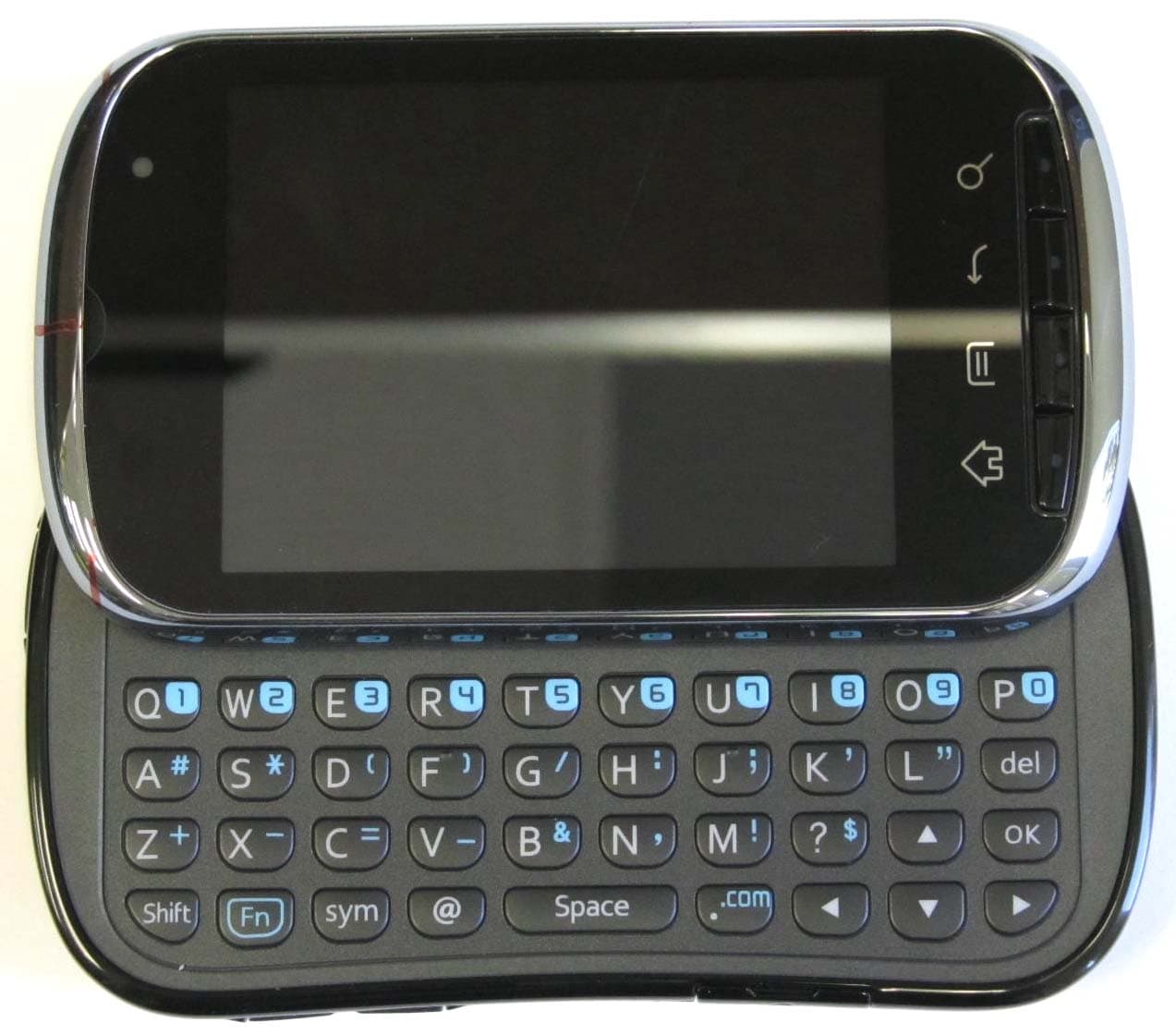
OVFC51213CD
Sep 01, 2011Tri-Band CDMA Mobile Phone with Bluetooth+WiFi
Equipment Class
DTS - Digital Transmission System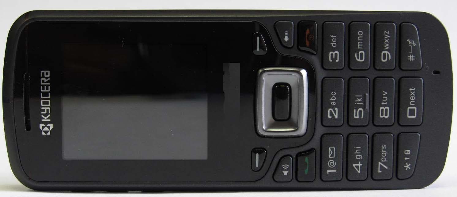
OVFS13503CB
May 17, 2011Tri-Band CDMA Phone
Equipment Class
PCE - PCS Licensed Transmitter held to ear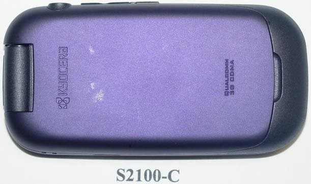
OVF-K5502
Jan 24, 2011Tri-Band CDMA Phone
Equipment Class
PCE - PCS Licensed Transmitter held to ear
OVF-K5501
Nov 07, 2010Single Band CDMA Cellular Phone with Bluetooth
Equipment Class
PCE - PCS Licensed Transmitter held to ear
OVF-C4700
Aug 09, 2010Cellular/PCS WCDMA/GSM/GPRS/EDGE phone with Bluetooth
Equipment Class
PCE - PCS Licensed Transmitter held to ear